Manual
Page 1
GA-H57M-USB3 GA-H55M-USB3 LGA1156 socket motherboard for Intel® Core™ i7 processor family/ Intel® Core™ i5 processor family/ Intel® Core™ i3 processor family User's Manual Rev. 1001 12ME-H57MUB3-1001R
GA-H57M-USB3 GA-H55M-USB3 LGA1156 socket motherboard for Intel® Core™ i7 processor family/ Intel® Core™ i5 processor family/ Intel® Core™ i3 processor family User's Manual Rev. 1001 12ME-H57MUB3-1001R
Manual
Page 2
Motherboard GA-H57M-USB3/GA-H55M-USB3 Jan. 14, 2010 Motherboard GA-H57M-USB3/ GA-H55M-USB3 Jan. 14, 2010
Motherboard GA-H57M-USB3/GA-H55M-USB3 Jan. 14, 2010 Motherboard GA-H57M-USB3/ GA-H55M-USB3 Jan. 14, 2010

Manual
Page 3
... information. Check your motherboard looks like this manual may be reproduced, copied, translated, transmitted, or published in the use GIGABYTE's unique features, read the User's Manual. All rights reserved. The trademarks mentioned in this manual are legally registered to use of ...this product, GIGABYTE provides the following types of documentations: For quick set-up of this : "REV: X.X." Copyright © 2010 GIGA-BYTE TECHNOLOGY ...
... information. Check your motherboard looks like this manual may be reproduced, copied, translated, transmitted, or published in the use GIGABYTE's unique features, read the User's Manual. All rights reserved. The trademarks mentioned in this manual are legally registered to use of ...this product, GIGABYTE provides the following types of documentations: For quick set-up of this : "REV: X.X." Copyright © 2010 GIGA-BYTE TECHNOLOGY ...
Manual
Page 4
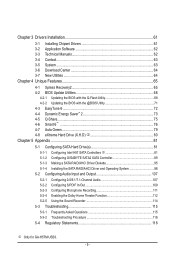
Table of Contents Box Contents...6 Optional Items...6 GA-H57M-USB3/GA-H55M-USB3 Motherboard Layout 7 GA-H57M-USB3/GA-H55M-USB3 Motherboard Block Diagram 8 Chapter 1 Hardware Installation 9 1-1 Installation Precautions 9 1-2 Product Specifications 10 1-3 Installing the CPU and CPU Cooler 13 1-3-1 Installing the CPU 13 1-3-2 Installing the CPU ...
Table of Contents Box Contents...6 Optional Items...6 GA-H57M-USB3/GA-H55M-USB3 Motherboard Layout 7 GA-H57M-USB3/GA-H55M-USB3 Motherboard Block Diagram 8 Chapter 1 Hardware Installation 9 1-1 Installation Precautions 9 1-2 Product Specifications 10 1-3 Installing the CPU and CPU Cooler 13 1-3-1 Installing the CPU 13 1-3-2 Installing the CPU ...
Manual
Page 5
...; ...76 4-7 Auto Green...79 4-8 eXtreme Hard Drive (X.H.D) j 80 Chapter 5 Appendix...81 5-1 Configuring SATA Hard Drive(s 81 5-1-1 Configuring Intel H57 SATA Controllers j 81 5-1-2 Configuring GIGABYTE SATA2 SATA Controller 89 5-1-3 Making a SATA RAID/AHCI Driver Diskette 95 5-1-4 Installing the SATA RAID/AHCI Driver and Operating System 96 5-2 Configuring Audio Input and... Theater Function 112 5-2-5 Using the Sound Recorder 114 5-3 Troubleshooting 115 5-3-1 Frequently Asked Questions 115 5-3-2 Troubleshooting Procedure 116 5-4 Regulatory Statements 118 j Only for GA-H57M-USB3. - 5 -
...; ...76 4-7 Auto Green...79 4-8 eXtreme Hard Drive (X.H.D) j 80 Chapter 5 Appendix...81 5-1 Configuring SATA Hard Drive(s 81 5-1-1 Configuring Intel H57 SATA Controllers j 81 5-1-2 Configuring GIGABYTE SATA2 SATA Controller 89 5-1-3 Making a SATA RAID/AHCI Driver Diskette 95 5-1-4 Installing the SATA RAID/AHCI Driver and Operating System 96 5-2 Configuring Audio Input and... Theater Function 112 5-2-5 Using the Sound Recorder 114 5-3 Troubleshooting 115 5-3-1 Frequently Asked Questions 115 5-3-2 Troubleshooting Procedure 116 5-4 Regulatory Statements 118 j Only for GA-H57M-USB3. - 5 -
Manual
Page 6
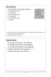
Box Contents GA-H57M-USB3 or GA-H55M-USB3 motherboard Motherboard driver disk User's Manual Quick Installation Guide One IDE cable Two SATA 3Gb/s cables I/O Shield • The box contents above are subject to ...
Box Contents GA-H57M-USB3 or GA-H55M-USB3 motherboard Motherboard driver disk User's Manual Quick Installation Guide One IDE cable Two SATA 3Gb/s cables I/O Shield • The box contents above are subject to ...
Manual
Page 7
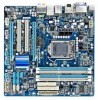
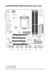
k Only for GA-H57M-USB3. GA-H57M-USB3/GA-H55M-USB3 Motherboard Layout KB_USB VGA_DVI ATX_12V_2X4 CPU_FAN SYS_FAN DP_HDMI_SPDIF ESATA_1394_USB USB30_LAN NEC D720200F1 LGA1156 PHASE LED IT8720 IDE ATX FDD AUDIO F_AUDIO PCIEX16 RTL8111D SPDIF_O SPDIF_I CODEC PCI1 PCI2 PCIEX4_X1 BAT GA-H57M-USB3/ GA-H55M-USB3 DDR3_2 DDR3_1 DDR3_4 DDR3_3 TSB43AB23 Intel® H57 j Intel® H55 k GIGABYTE SATA2 B_BIOS SATA2_0 M_BIOS SATA2_1 SATA2_3 GSATA2_6 SATA2_2 SATA2_4 GSATA2_5 CLR_CMOS CD_IN COMA F_1394 F_USB4j F_USB3 F_USB2 F_USB1 F_PANEL j Only for GA-H55M-USB3. - 7 -
k Only for GA-H57M-USB3. GA-H57M-USB3/GA-H55M-USB3 Motherboard Layout KB_USB VGA_DVI ATX_12V_2X4 CPU_FAN SYS_FAN DP_HDMI_SPDIF ESATA_1394_USB USB30_LAN NEC D720200F1 LGA1156 PHASE LED IT8720 IDE ATX FDD AUDIO F_AUDIO PCIEX16 RTL8111D SPDIF_O SPDIF_I CODEC PCI1 PCI2 PCIEX4_X1 BAT GA-H57M-USB3/ GA-H55M-USB3 DDR3_2 DDR3_1 DDR3_4 DDR3_3 TSB43AB23 Intel® H57 j Intel® H55 k GIGABYTE SATA2 B_BIOS SATA2_0 M_BIOS SATA2_1 SATA2_3 GSATA2_6 SATA2_2 SATA2_4 GSATA2_5 CLR_CMOS CD_IN COMA F_1394 F_USB4j F_USB3 F_USB2 F_USB1 F_PANEL j Only for GA-H55M-USB3. - 7 -
Manual
Page 8
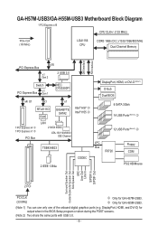
...in the BIOS Setup program or when during the POST screens. (Note 2) Two share the same ports with USB 3.0. - 8 - GA-H57M-USB3/GA-H55M-USB3 Motherboard Block Diagram 1 PCI Express x16 CPU CLK+/- (133 MHz) PCIe CLK (100 MHz) LGA1156 CPU DDR3 1666 (O.C.)/1333/1066/...800 MHz Dual Channel Memory DMI Interface FDI Interface x16 PCI Express Bus x1 Gen 2 2 USB 3.0 Switch PCI Express Bus x1 Gen 1 NEC D720200F1 x4/ X1 x1 x1 RTL8111D RJ45 GIGABYTE...
...in the BIOS Setup program or when during the POST screens. (Note 2) Two share the same ports with USB 3.0. - 8 - GA-H57M-USB3/GA-H55M-USB3 Motherboard Block Diagram 1 PCI Express x16 CPU CLK+/- (133 MHz) PCIe CLK (100 MHz) LGA1156 CPU DDR3 1666 (O.C.)/1333/1066/...800 MHz Dual Channel Memory DMI Interface FDI Interface x16 PCI Express Bus x1 Gen 2 2 USB 3.0 Switch PCI Express Bus x1 Gen 1 NEC D720200F1 x4/ X1 x1 x1 RTL8111D RJ45 GIGABYTE...
Manual
Page 9
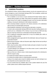
If you are uncertain about any metal leads or connectors. • It is best to wear an electrostatic discharge (ESD) wrist strap when handling electronic com- Prior to installation, carefully read the user's manual and follow these procedures: • Prior to installation, do not remove or break motherboard S/N (Serial Number) sticker or warranty sticker provided by unplugging the power cord from the motherboard, make sure the power supply has been turned off. • Before turning on the power, make sure the power supply voltage has been set according to the local voltage standard....
If you are uncertain about any metal leads or connectors. • It is best to wear an electrostatic discharge (ESD) wrist strap when handling electronic com- Prior to installation, carefully read the user's manual and follow these procedures: • Prior to installation, do not remove or break motherboard S/N (Serial Number) sticker or warranty sticker provided by unplugging the power cord from the motherboard, make sure the power supply has been turned off. • Before turning on the power, make sure the power supply voltage has been set according to the local voltage standard....
Manual
Page 10
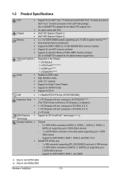
... 1, RAID 5, and RAID 10 j w GIGABYTE SATA2 chip: - 1 x IDE connector supporting ATA-133/100/66/33 and up to 2 IDE devices - 2 x SATA 3Gb/s connectors (GSATA2_5, GSATA2_6) supporting up to 2 SATA 3Gb/s devices - k Only for GA-H57M-USB3. Hardware Installation - 10 - Support for SATA RAID 0, RAID 1, and JBOD j Only for GA-H55M-USB3. 1-2 Product Specifications CPU w w Chipset w ...
... 1, RAID 5, and RAID 10 j w GIGABYTE SATA2 chip: - 1 x IDE connector supporting ATA-133/100/66/33 and up to 2 IDE devices - 2 x SATA 3Gb/s connectors (GSATA2_5, GSATA2_6) supporting up to 2 SATA 3Gb/s devices - k Only for GA-H57M-USB3. Hardware Installation - 10 - Support for SATA RAID 0, RAID 1, and JBOD j Only for GA-H55M-USB3. 1-2 Product Specifications CPU w w Chipset w ...
Manual
Page 11
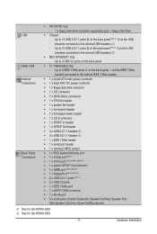
... w 1 x eSATA 3Gb/s connector w 1 x RJ-45 port w 6 x audio jacks (Center/Subwoofer Speaker Out/Rear Speaker Out/ Side Speaker Out/Line In/Line Out/Microphone) j Only for GA-H55M-USB3. - 11 - Up to 14 USB 2.0/1.1 ports (6 on the back panel, 1 via the IEEE 1394a bracket connected to the internal USB headers) k w NEC D720200F1 chip: - k Only...
... w 1 x eSATA 3Gb/s connector w 1 x RJ-45 port w 6 x audio jacks (Center/Subwoofer Speaker Out/Rear Speaker Out/ Side Speaker Out/Line In/Line Out/Microphone) j Only for GA-H55M-USB3. - 11 - Up to 14 USB 2.0/1.1 ports (6 on the back panel, 1 via the IEEE 1394a bracket connected to the internal USB headers) k w NEC D720200F1 chip: - k Only...
Manual
Page 12
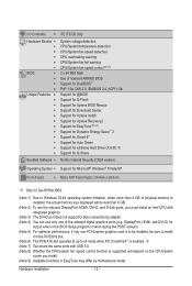
... 7) Two share the same ports with integrated graphics. (Note 3) The DVI-D port does not support D-Sub connection by motherboard model. DisplayPort, HDMI, and DVI-D) for GA-H57M-USB3. (Note 1) Due to Windows 32-bit operating system limitation, when more than 4 GB. (Note 2) To use only one PCI Express graphics card is enabled.
... 7) Two share the same ports with integrated graphics. (Note 3) The DVI-D port does not support D-Sub connection by motherboard model. DisplayPort, HDMI, and DVI-D) for GA-H57M-USB3. (Note 1) Due to Windows 32-bit operating system limitation, when more than 4 GB. (Note 2) To use only one PCI Express graphics card is enabled.

Manual
Page 13
... CPU Notch Notch Triangle Pin One Marking on the computer if the CPU cooler is not recommended that the motherboard supports the CPU. (Go to GIGABYTE's website for the peripherals. Hardware Installation Locate the alignment keys on the motherboard CPU socket and the notches on the CPU. If you wish to...
... CPU Notch Notch Triangle Pin One Marking on the computer if the CPU cooler is not recommended that the motherboard supports the CPU. (Go to GIGABYTE's website for the peripherals. Hardware Installation Locate the alignment keys on the motherboard CPU socket and the notches on the CPU. If you wish to...

Manual
Page 14
Follow the steps below to the "REMOVE" mark) and then remove the cover. (DO NOT touch socket contacts. Hold your index finger down and away from the power outlet to prevent damage to the CPU. Step 5: Push the CPU socket lever back into the motherboard CPU socket. Step 2: Remove the CPU socket cover as well. Align the CPU pin one marking (triangle) with the socket alignment keys) and gently insert the CPU into position. B. When replacing the load plate, make sure to turn off the computer and unplug the power cord from the socket with your thumb to lift up the front ...
Follow the steps below to the "REMOVE" mark) and then remove the cover. (DO NOT touch socket contacts. Hold your index finger down and away from the power outlet to prevent damage to the CPU. Step 5: Push the CPU socket lever back into the motherboard CPU socket. Step 2: Remove the CPU socket cover as well. Align the CPU pin one marking (triangle) with the socket alignment keys) and gently insert the CPU into position. B. When replacing the load plate, make sure to turn off the computer and unplug the power cord from the socket with your thumb to lift up the front ...

Manual
Page 15
Direction of the Arrow Sign on the Male Push Pin Male Push Pin The Top of Female Push Pin Female Push Pin Step 2: Before installing the cooler, note the direction of the arrow sign on the male push pin. (Turning the push pin along the direction of arrow is to remove the cooler, on the contrary, is to install.) Step 3: Place the cooler atop the CPU, aligning the four push pins through the pin holes on installing the cooler.) Step 5: After the installation, check the back of the motherboard. Step 4: You should hear a "click" when pushing down on the push pins diagonally. ...
Direction of the Arrow Sign on the Male Push Pin Male Push Pin The Top of Female Push Pin Female Push Pin Step 2: Before installing the cooler, note the direction of the arrow sign on the male push pin. (Turning the push pin along the direction of arrow is to remove the cooler, on the contrary, is to install.) Step 3: Place the cooler atop the CPU, aligning the four push pins through the pin holes on installing the cooler.) Step 5: After the installation, check the back of the motherboard. Step 4: You should hear a "click" when pushing down on the push pins diagonally. ...
Manual
Page 16
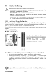
... direction. 1-4-1 Dual Channel Memory Configuration This motherboard provides four DDR3 memory sockets and supports Dual Channel Technology. The four DDR3 memory sockets are unable to GIGABYTE's website for optimum performance. When enabling Dual Channel mode with two memory modules, be installed in Dual Channel mode. 1. Four Modules DS/SS DS/SS...
... direction. 1-4-1 Dual Channel Memory Configuration This motherboard provides four DDR3 memory sockets and supports Dual Channel Technology. The four DDR3 memory sockets are unable to GIGABYTE's website for optimum performance. When enabling Dual Channel mode with two memory modules, be installed in Dual Channel mode. 1. Four Modules DS/SS DS/SS...
Manual
Page 17
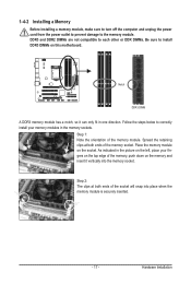
Step 2: The clips at both ends of the memory socket. Place the memory module on the top edge of the memory module. Spread the retaining clips at both ends of the socket will snap into the memory socket. As indicated in the picture on the left, place your memory modules in one direction. Hardware Installation Notch DDR3 DIMM A DDR3 memory module has a notch, so it vertically into place when the memory module is securely inserted. - 17 - Step 1: Note the orientation of the memory, push down on the memory and insert it can only fit in the memory sockets. DDR3 and ...
Step 2: The clips at both ends of the memory socket. Place the memory module on the top edge of the memory module. Spread the retaining clips at both ends of the socket will snap into the memory socket. As indicated in the picture on the left, place your memory modules in one direction. Hardware Installation Notch DDR3 DIMM A DDR3 memory module has a notch, so it vertically into place when the memory module is securely inserted. - 17 - Step 1: Note the orientation of the memory, push down on the memory and insert it can only fit in the memory sockets. DDR3 and ...

Manual
Page 18
PCI Express x16 Slot PCI Slot Follow the steps below to correctly install your operating system. Align the card with your expansion card(s). 7. Make sure the metal contacts on the card until it is fully seated in your expansion card in the slot and does not rock. • Removing the Card: Press the white latch at the end of the card until it is securely seated in the expansion slot. 1. Secure the card's metal bracket to the chassis back panel with the expansion card in the slot. 3. Hardware Installation - 18 - Turn on the top edge of the PCI Express slot to release...
PCI Express x16 Slot PCI Slot Follow the steps below to correctly install your operating system. Align the card with your expansion card(s). 7. Make sure the metal contacts on the card until it is fully seated in your expansion card in the slot and does not rock. • Removing the Card: Press the white latch at the end of the card until it is securely seated in the expansion slot. 1. Secure the card's metal bracket to the chassis back panel with the expansion card in the slot. 3. Hardware Installation - 18 - Turn on the top edge of the PCI Express slot to release...

Manual
Page 19
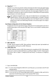
Connect a monitor that supports DVI-D connection to this port. HDMI Port (Note 1) (Note 3) The HDMI (High-Definition Multimedia Interface) provides an all-digital audio/video interface to this port. Connect a monitor that supports D-Sub connection to transmit the uncompressed audio/video signals and is the HDMI device. (The item name may differ from operating system. Hardware Installation D-Sub Port (Note 1) The D-Sub port supports a 15-pin D-Sub connector. Before using this port for sound playback is HDCP compliant. Refer to the default playback device. - 19 - ...
Connect a monitor that supports DVI-D connection to this port. HDMI Port (Note 1) (Note 3) The HDMI (High-Definition Multimedia Interface) provides an all-digital audio/video interface to this port. Connect a monitor that supports D-Sub connection to transmit the uncompressed audio/video signals and is the HDMI device. (The item name may differ from operating system. Hardware Installation D-Sub Port (Note 1) The D-Sub port supports a 15-pin D-Sub connector. Before using this port for sound playback is HDCP compliant. Refer to the default playback device. - 19 - ...
Manual
Page 20
..., DVI-D, and D-Sub ports, you must install an Intel CPU with SATA 1.5Gb/s standard. After installing the DisplayPort device, make sure the default device for GA-H57M-USB3. (Note 1) To use only one of 2560x1600p but the actual resolutions supported depend on configuring a RAID array. The H57j Chipset supports RAID function. Use...
..., DVI-D, and D-Sub ports, you must install an Intel CPU with SATA 1.5Gb/s standard. After installing the DisplayPort device, make sure the default device for GA-H57M-USB3. (Note 1) To use only one of 2560x1600p but the actual resolutions supported depend on configuring a RAID array. The H57j Chipset supports RAID function. Use...
