Manual
Page 3
...://www.gigabyte.com.tw Identifying Your Motherboard Revision The revision number on your motherboard revision before updating motherboard BIOS, drivers, or when looking for technical information. For example, "REV: 1.0" means the revision of the motherboard is the property of documentations: For detailed product information, carefully read or download the information on/from the Support&Downloads\Motherboard\Technology Guide page on how to the specifications...
...://www.gigabyte.com.tw Identifying Your Motherboard Revision The revision number on your motherboard revision before updating motherboard BIOS, drivers, or when looking for technical information. For example, "REV: 1.0" means the revision of the motherboard is the property of documentations: For detailed product information, carefully read or download the information on/from the Support&Downloads\Motherboard\Technology Guide page on how to the specifications...
Manual
Page 4
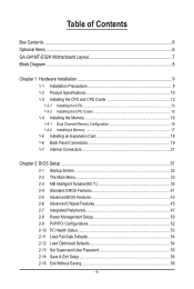
Table of Contents Box Contents...6 Optional Items...6 GA-G41MT-ES2H Motherboard Layout 7 Block Diagram...8 Chapter 1 Hardware Installation 9 1-1 Installation Precautions 9 1-2 Product Specifications 10 1-3 Installing the CPU and CPU Cooler 13 1-3-1 Installing the CPU 13 1-3-2 Installing the CPU Cooler 15 1-4 Installing the Memory 16 1-4-1 Dual Channel Memory Configuration 16 1-4-2 Installing a Memory 17 1-5 Installing an Expansion Card 18 1-6 Back Panel Connectors 19 1-7 Internal Connectors 21 Chapter 2 BIOS Setup 31 2-1 Startup Screen 32 2-2 The Main Menu 33 2-3 MB Intelligent...
Table of Contents Box Contents...6 Optional Items...6 GA-G41MT-ES2H Motherboard Layout 7 Block Diagram...8 Chapter 1 Hardware Installation 9 1-1 Installation Precautions 9 1-2 Product Specifications 10 1-3 Installing the CPU and CPU Cooler 13 1-3-1 Installing the CPU 13 1-3-2 Installing the CPU Cooler 15 1-4 Installing the Memory 16 1-4-1 Dual Channel Memory Configuration 16 1-4-2 Installing a Memory 17 1-5 Installing an Expansion Card 18 1-6 Back Panel Connectors 19 1-7 Internal Connectors 21 Chapter 2 BIOS Setup 31 2-1 Startup Screen 32 2-2 The Main Menu 33 2-3 MB Intelligent...
Manual
Page 6
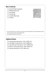
... Contents GA-G41MT-ES2H motherboard Motherboard driver disk User's Manual One IDE cable Two SATA 3Gb/s cables I/O Shield • The box contents above are subject to change without notice. • The motherboard image is for reference only and the actual items shall depend on the product package you obtain. Optional Items Floppy disk drive cable (Part No. 12CF1-1FD001-7*R) 2-port USB 2.0 bracket (Part No. 12CR1-1UB030-5*R) 2-port SATA power cable (Part No. 12CF1-2SERPW-0*R) S/PDIF In and Out cable (Part No...
... Contents GA-G41MT-ES2H motherboard Motherboard driver disk User's Manual One IDE cable Two SATA 3Gb/s cables I/O Shield • The box contents above are subject to change without notice. • The motherboard image is for reference only and the actual items shall depend on the product package you obtain. Optional Items Floppy disk drive cable (Part No. 12CF1-1FD001-7*R) 2-port USB 2.0 bracket (Part No. 12CR1-1UB030-5*R) 2-port SATA power cable (Part No. 12CF1-2SERPW-0*R) S/PDIF In and Out cable (Part No...

Manual
Page 12
... actual memory size displayed will be less than 4 GB. (Note 2) The DVI-D port does not support D-Sub connection by adapter. (Note 3) To configure 7.1-channel audio, you need connect with the port of HD Audio standard via front panel and enable the multi-channel audio feature through the audio driver. (Note 4) Whether the CPU fan speed control function is supported will depend on the CPU cooler you install. (Note 5) Available functions in EasyTune may differ by motherboard model...
... actual memory size displayed will be less than 4 GB. (Note 2) The DVI-D port does not support D-Sub connection by adapter. (Note 3) To configure 7.1-channel audio, you need connect with the port of HD Audio standard via front panel and enable the multi-channel audio feature through the audio driver. (Note 4) Whether the CPU fan speed control function is supported will depend on the CPU cooler you install. (Note 5) Available functions in EasyTune may differ by motherboard model...

Manual
Page 16
.... Dual Channel mode cannot be used . (Go to GIGABYTE's website for the latest memory support list.) • Always turn off the computer and unplug the power cord from the power outlet before installing the memory to install the memory: • Make sure that the motherboard supports the memory. Hardware Installation - 16 - When enabling Dual Channel mode with two memory modules, it is recommended that memory of the same capacity, brand, speed, and chips be installed in Dual Channel mode. 1. After the memory...
.... Dual Channel mode cannot be used . (Go to GIGABYTE's website for the latest memory support list.) • Always turn off the computer and unplug the power cord from the power outlet before installing the memory to install the memory: • Make sure that the motherboard supports the memory. Hardware Installation - 16 - When enabling Dual Channel mode with two memory modules, it is recommended that memory of the same capacity, brand, speed, and chips be installed in Dual Channel mode. 1. After the memory...
Manual
Page 18
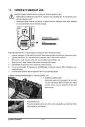
... the expansion slot. 1. After installing all expansion cards, replace the chassis cover(s). 6. If necessary, go to BIOS Setup to make any required BIOS changes for your computer. Install the driver provided with your expansion card. • Always turn off the computer and unplug the power cord from the power outlet before you begin to install an expansion card: • Make sure the motherboard supports the expansion card. PCI Express x16 Slot PCI Slot Follow the...
... the expansion slot. 1. After installing all expansion cards, replace the chassis cover(s). 6. If necessary, go to BIOS Setup to make any required BIOS changes for your computer. Install the driver provided with your expansion card. • Always turn off the computer and unplug the power cord from the power outlet before you begin to install an expansion card: • Make sure the motherboard supports the expansion card. PCI Express x16 Slot PCI Slot Follow the...

Manual
Page 20
... is enabled.) • HDCP compliant monitor(s) USB 2.0/1.1 Port The USB port supports the USB 2.0/1.1 specification. Use this audio jack for line in a 4/5.1-channel audio configuration. Microphones must be output from the HDMI port. Dual Display Configurations: This motherboard provides three display ports, DVI-D, HDMI, and D-Sub ports and supports dual-display configurations. Line Out Jack (Green) The default line out jack. B. Use this configuration, the BIOS Setup and POST screens can be used to connect front speakers in devices such as a USB keyboard/mouse, USB...
... is enabled.) • HDCP compliant monitor(s) USB 2.0/1.1 Port The USB port supports the USB 2.0/1.1 specification. Use this audio jack for line in a 4/5.1-channel audio configuration. Microphones must be output from the HDMI port. Dual Display Configurations: This motherboard provides three display ports, DVI-D, HDMI, and D-Sub ports and supports dual-display configurations. Line Out Jack (Green) The default line out jack. B. Use this configuration, the BIOS Setup and POST screens can be used to connect front speakers in devices such as a USB keyboard/mouse, USB...
Manual
Page 28
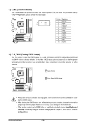
...; After clearing the CMOS values and before turning on the two pins to temporarily short the two pins or use a metal object like a screwdriver to Chapter 2, "BIOS Setup," for a few seconds. Failure to do so may cause damage to the motherboard. • After system restart, go to BIOS Setup to load factory defaults (select Load Optimized Defaults) or manually configure the BIOS settings (refer to touch the two pins for BIOS configurations). 13) COMA (Serial Port Header...
...; After clearing the CMOS values and before turning on the two pins to temporarily short the two pins or use a metal object like a screwdriver to Chapter 2, "BIOS Setup," for a few seconds. Failure to do so may cause damage to the motherboard. • After system restart, go to BIOS Setup to load factory defaults (select Load Optimized Defaults) or manually configure the BIOS settings (refer to touch the two pins for BIOS configurations). 13) COMA (Serial Port Header...

Manual
Page 31
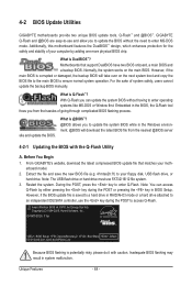
... power is turned on using the current version of BIOS, it is a Windows-based utility that you do it with caution. To upgrade the BIOS, use either the GIGABYTE Q-Flash or @BIOS utility. • Q-Flash allows the user to Chapter 4, "BIOS Update Utilities." • Because BIOS flashing is potentially risky, if you not flash the BIOS. For instructions on . Refer to Chapter 5, "Troubleshooting," for how to prevent system instability or other unexpected results. BIOS Setup When the power...
... power is turned on using the current version of BIOS, it is a Windows-based utility that you do it with caution. To upgrade the BIOS, use either the GIGABYTE Q-Flash or @BIOS utility. • Q-Flash allows the user to Chapter 4, "BIOS Update Utilities." • Because BIOS flashing is potentially risky, if you not flash the BIOS. For instructions on . Refer to Chapter 5, "Troubleshooting," for how to prevent system instability or other unexpected results. BIOS Setup When the power...

Manual
Page 34
... BIOS Setup. First enter the profile name (to erase the default profile name, use this function to load the BIOS settings from BIOS If your CPU, memory, etc. Standard CMOS Features Use this menu to configure the system time and date, hard drive types, floppy disk drive types, and the type of the and keys (For the Main Menu Only) F11: Save CMOS to BIOS This function allows you to view the BIOS settings but not to make changes...
... BIOS Setup. First enter the profile name (to erase the default profile name, use this function to load the BIOS settings from BIOS If your CPU, memory, etc. Standard CMOS Features Use this menu to configure the system time and date, hard drive types, floppy disk drive types, and the type of the and keys (For the Main Menu Only) F11: Save CMOS to BIOS This function allows you to view the BIOS settings but not to make changes...

Manual
Page 35
... CPU Host Clock Control x CPU Host Frequency (Mhz) PCI Express Frequency (Mhz) [Disabled] 200 [Auto] ******** DRAM Performance Control ******** Performance Enhance [Standard] System Memory Multiplier (SPD) [Auto] Memory Frequency (Mhz) 1333 800 DRAM Timing Selectable (SPD) [Auto] >>>>> Standard Timing Control x CAS Latency Time 9 Auto x tRCD 9 Auto Move Enter: Select F5: Previous Values +/-/PU/PD: Value F10: Save F6: Fail-Safe Defaults ESC: Exit F1: General Help F7: Optimized Defaults CMOS Setup Utility-Copyright (C) 1984-2009 Award Software...
... CPU Host Clock Control x CPU Host Frequency (Mhz) PCI Express Frequency (Mhz) [Disabled] 200 [Auto] ******** DRAM Performance Control ******** Performance Enhance [Standard] System Memory Multiplier (SPD) [Auto] Memory Frequency (Mhz) 1333 800 DRAM Timing Selectable (SPD) [Auto] >>>>> Standard Timing Control x CAS Latency Time 9 Auto x tRCD 9 Auto Move Enter: Select F5: Previous Values +/-/PU/PD: Value F10: Save F6: Fail-Safe Defaults ESC: Exit F1: General Help F7: Optimized Defaults CMOS Setup Utility-Copyright (C) 1984-2009 Award Software...

Manual
Page 36
...CPU Frequency Displays the current operating CPU frequency. ******** Clock Chip Control Standard Clock Control CPU Host Clock Control Enables or disables the control of the graphics chip and memory. PCI Express Frequency (Mhz) Allows you install a CPU that the CPU frequency be configurable. Robust Graphics Booster Robust Graphics Booster (R.G.B.) helps to manually set the PCIe clock frequency. Enabled will allow for automated system reboot, or clear the CMOS values to reset the board to default values. (Default: Disabled) CPU Host Frequency (Mhz) Allows you to manually set...
...CPU Frequency Displays the current operating CPU frequency. ******** Clock Chip Control Standard Clock Control CPU Host Clock Control Enables or disables the control of the graphics chip and memory. PCI Express Frequency (Mhz) Allows you install a CPU that the CPU frequency be configurable. Robust Graphics Booster Robust Graphics Booster (R.G.B.) helps to manually set the PCIe clock frequency. Enabled will allow for automated system reboot, or clear the CMOS values to reset the board to default values. (Default: Disabled) CPU Host Frequency (Mhz) Allows you to manually set...

Manual
Page 43
... for entering the BIOS Setup program. (Default) System A password is required every time the system boots, or only when you install a CPU that supports this item, set the password(s) under the Set Supervisor/User Password item in the BIOS Main Menu. Capability Enables or disables the S.M.A.R.T. (Self Monitoring and Reporting Technology) capability of your system to report read/write errors of loading the operating system from the available devices. This feature allows your hard drive. Press...
... for entering the BIOS Setup program. (Default) System A password is required every time the system boots, or only when you install a CPU that supports this item, set the password(s) under the Set Supervisor/User Password item in the BIOS Main Menu. Capability Enables or disables the S.M.A.R.T. (Self Monitoring and Reporting Technology) capability of your system to report read/write errors of loading the operating system from the available devices. This feature allows your hard drive. Press...

Manual
Page 45
... (e.g. BIOS Setup PAVP Mode Enables or disables PAVP mode. If you wish to playback HDCP contents. Enable this function if you wish to set up a dual view configuration, set this item to any user application. Aero (DWM) in Windows Vista will always be turned off in this function. This memory is installed. Disabled Disables this mode. - 45 - PEG Sets the PCI Express graphics card as the first display. 2-6 Advanced Chipset Features CMOS Setup Utility-Copyright (C) 1984-2009 Award Software Advanced Chipset Features ** VGA Setting ** Onboard VGA...
... (e.g. BIOS Setup PAVP Mode Enables or disables PAVP mode. If you wish to playback HDCP contents. Enable this function if you wish to set up a dual view configuration, set this item to any user application. Aero (DWM) in Windows Vista will always be turned off in this function. This memory is installed. Disabled Disables this mode. - 45 - PEG Sets the PCI Express graphics card as the first display. 2-6 Advanced Chipset Features CMOS Setup Utility-Copyright (C) 1984-2009 Award Software Advanced Chipset Features ** VGA Setting ** Onboard VGA...

Manual
Page 47
... set to operate in PATA mode. When PATA IDE Set to is dependent on the On-Chip SATA Mode and PATA IDE Set to Ch. 1 Master/Slave, this option will be used simultaneously: two PATA devices plus two SATA devices. Ch.0 Master/Slave Sets the IDE channels to Ch. 0 Master/Slave. (Default) Ch.1 Master/Slave Sets the IDE channels to Azalia Codec Onboard H/W LAN Green LAN } SMART LAN Onboard LAN Boot ROM Onboard Serial Port 1 USB 1.0 Controller USB 2.0 Controller USB Keyboard Support USB Mouse Support USB Storage Function [Enabled] [Auto...
... set to operate in PATA mode. When PATA IDE Set to is dependent on the On-Chip SATA Mode and PATA IDE Set to Ch. 1 Master/Slave, this option will be used simultaneously: two PATA devices plus two SATA devices. Ch.0 Master/Slave Sets the IDE channels to Ch. 0 Master/Slave. (Default) Ch.1 Master/Slave Sets the IDE channels to Azalia Codec Onboard H/W LAN Green LAN } SMART LAN Onboard LAN Boot ROM Onboard Serial Port 1 USB 1.0 Controller USB 2.0 Controller USB Keyboard Support USB Mouse Support USB Storage Function [Enabled] [Auto...

Manual
Page 48
.... (Default: Auto) If you wish to install a 3rd party add-in network card instead of using the onboard audio, set this item to Disabled. Green LAN When the onboard LAN function and Green LAN are enabled, the system will be disabled automatically. (Default: Disabled) SMART LAN (LAN Cable Diagnostic Function) CMOS Setup Utility-Copyright (C) 1984-2009 Award Software SMART LAN Start detecting at a speed of 10/100 Mbps in MS-DOS mode; Onboard H/W LAN Enables or disables the onboard LAN function. (Default: Enabled) If you wish to the fault or short...
.... (Default: Auto) If you wish to install a 3rd party add-in network card instead of using the onboard audio, set this item to Disabled. Green LAN When the onboard LAN function and Green LAN are enabled, the system will be disabled automatically. (Default: Disabled) SMART LAN (LAN Cable Diagnostic Function) CMOS Setup Utility-Copyright (C) 1984-2009 Award Software SMART LAN Start detecting at a speed of 10/100 Mbps in MS-DOS mode; Onboard H/W LAN Enables or disables the onboard LAN function. (Default: Enabled) If you wish to the fault or short...

Manual
Page 49
... USB storage devices, including USB flash drives and USB hard drives during the POST. (Default: Enabled) - 49 - BIOS Setup If a cable problem occurs on Part 1-2. Onboard LAN Boot ROM Allows you to decide whether to the fault or short. USB 2.0 Controller Enables or disables the integrated USB 2.0 controller. (Default: Enabled) USB Keyboard Function Allows USB keyboard to be used in MS-DOS. (Default: Disabled) USB Mouse Function Allows USB mouse to be the approximate distance to activate the boot ROM integrated with the onboard LAN chip. (Default: Disabled) Onboard Serial Port...
... USB storage devices, including USB flash drives and USB hard drives during the POST. (Default: Enabled) - 49 - BIOS Setup If a cable problem occurs on Part 1-2. Onboard LAN Boot ROM Allows you to decide whether to the fault or short. USB 2.0 Controller Enables or disables the integrated USB 2.0 controller. (Default: Enabled) USB Keyboard Function Allows USB keyboard to be used in MS-DOS. (Default: Disabled) USB Mouse Function Allows USB mouse to be the approximate distance to activate the boot ROM integrated with the onboard LAN chip. (Default: Disabled) Onboard Serial Port...
Manual
Page 64
... main BIOS. What is saved to -use and allow you can access Q-Flash by adding one more physical BIOS chip. Embedded in the BIOS, the Q-Flash tool frees you to update the system BIOS while in RAID/AHCI mode or a hard drive attached to ensure normal system operation. Additionally, this motherboard features the DualBIOS™ design, which enhances protection for the safety and stability of your motherboard model. 2. G41MT-ES2H F1ac . . . . : BIOS Setup : XpressRecovery2 : Boot Menu...
... main BIOS. What is saved to -use and allow you can access Q-Flash by adding one more physical BIOS chip. Embedded in the BIOS, the Q-Flash tool frees you to update the system BIOS while in RAID/AHCI mode or a hard drive attached to ensure normal system operation. Additionally, this motherboard features the DualBIOS™ design, which enhances protection for the safety and stability of your motherboard model. 2. G41MT-ES2H F1ac . . . . : BIOS Setup : XpressRecovery2 : Boot Menu...

Manual
Page 65
... In the main menu of the system reading the BIOS file from Drive Please SparevsesBaInOySketoy Dtoricvoentinue Enter : Run hi:Move ESC:Reset F10:Power Off - 65 - Update BIOS from the floppy disk is displayed on the screen. Step 3: When the update process is saved to a hard drive in RAID/AHCI mode or a hard drive attached to an independent IDE/SATA controller, use the up or down arrow key to select Update BIOS from Drive Save BIOS to access Q-Flash. 2. Q-Flash Utility v2.13 Flash Type/Size MXIC 25L8005...
... In the main menu of the system reading the BIOS file from Drive Please SparevsesBaInOySketoy Dtoricvoentinue Enter : Run hi:Move ESC:Reset F10:Power Off - 65 - Update BIOS from the floppy disk is displayed on the screen. Step 3: When the update process is saved to a hard drive in RAID/AHCI mode or a hard drive attached to an independent IDE/SATA controller, use the up or down arrow key to select Update BIOS from Drive Save BIOS to access Q-Flash. 2. Q-Flash Utility v2.13 Flash Type/Size MXIC 25L8005...
Manual
Page 81
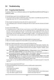
... reference only.) 1 short: System boots successfully 1 long, 3 short: Keyboard error 2 short: CMOS setting error 1 long, 9 short: BIOS ROM error 1 long, 1 short: Memory or motherboard error Continuous long beeps: Graphics card not inserted properly 1 long, 2 short: Monitor or graphics card error Continuous short beeps: Power error - 81 - In the Main Menu, press + to install. Q: Why is still on the motherboard battery in My Computer > Properties > Hardware > Device Manager > System Devices). For motherboards that have a clearing CMOS jumper, refer to the instructions on after...
... reference only.) 1 short: System boots successfully 1 long, 3 short: Keyboard error 2 short: CMOS setting error 1 long, 9 short: BIOS ROM error 1 long, 1 short: Memory or motherboard error Continuous long beeps: Graphics card not inserted properly 1 long, 2 short: Monitor or graphics card error Continuous short beeps: Power error - 81 - In the Main Menu, press + to install. Q: Why is still on the motherboard battery in My Computer > Properties > Hardware > Device Manager > System Devices). For motherboards that have a clearing CMOS jumper, refer to the instructions on after...


