Manual
Page 1
GA-G31M-ES2L/ GA-G31M-ES2C LGA775 socket motherboard for Intel® CoreTM processor family/ Intel® Pentium® processor family/Intel® Celeron® processor family User's Manual Rev. 2301 12ME-G31MES2L-2301R
GA-G31M-ES2L/ GA-G31M-ES2C LGA775 socket motherboard for Intel® CoreTM processor family/ Intel® Pentium® processor family/Intel® Celeron® processor family User's Manual Rev. 2301 12ME-G31MES2L-2301R
Manual
Page 2
Motherboard GA-G31M-ES2L/GA-G31M-ES2C May 20, 2010 Motherboard GA-G31M-ES2L/ GA-G31M-ES2C May 20, 2010
Motherboard GA-G31M-ES2L/GA-G31M-ES2C May 20, 2010 Motherboard GA-G31M-ES2L/ GA-G31M-ES2C May 20, 2010

Manual
Page 3
...features in this manual may be made by GIGABYTE without GIGABYTE's prior written permission. All rights reserved. Example: For product-related information, check on our website at: http://www.gigabyte.com.tw Identifying Your Motherboard Revision The revision number on our website....User's Manual. For instructions on how to use GIGABYTE's unique features, read or download the information on/from the Support&Downloads\Motherboard\Technology Guide page on your motherboard revision before updating motherboard BIOS, drivers, or when looking for technical information. Documentation ...
...features in this manual may be made by GIGABYTE without GIGABYTE's prior written permission. All rights reserved. Example: For product-related information, check on our website at: http://www.gigabyte.com.tw Identifying Your Motherboard Revision The revision number on our website....User's Manual. For instructions on how to use GIGABYTE's unique features, read or download the information on/from the Support&Downloads\Motherboard\Technology Guide page on your motherboard revision before updating motherboard BIOS, drivers, or when looking for technical information. Documentation ...
Manual
Page 4
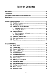
Table of Contents Box Contents ...6 OptionalItems...6 GA-G31M-ES2L/GA-G31M-ES2C Motherboard Layout 7 Block Diagram...8 Chapter 1 Hardware Installation 9 1-1 Installation Precautions 9 1-2 Product Specifications 10 1-3 Installing the CPU and CPU Cooler 13 1-3-1 Installing the CPU 13 1-3-2 Installing the CPU ...
Table of Contents Box Contents ...6 OptionalItems...6 GA-G31M-ES2L/GA-G31M-ES2C Motherboard Layout 7 Block Diagram...8 Chapter 1 Hardware Installation 9 1-1 Installation Precautions 9 1-2 Product Specifications 10 1-3 Installing the CPU and CPU Cooler 13 1-3-1 Installing the CPU 13 1-3-2 Installing the CPU ...
Manual
Page 6
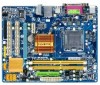
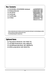
Optional Items Floppy disk drive cable (Part No. 12CF1-1FD001-7*R) 2-port USB 2.0 bracket (Part No. 12CR1-1UB030-5*R) 2-port SATA power cable (Part No. 12CF1-2SERPW-0*R) S/PDIF out cable (Part No. 12CR1-1SPOUT-0*R) - 6 - The box contents are for reference only. Box Contents GA-G31M-ES2L or GA-G31M-ES2C motherboard Motherboard driver disk User's Manual One IDE cable Two SATA cables I/O Shield • The box contents above are subject to change without notice. • The motherboard image is for reference only and the actual items shall depend on product package you obtain.
Optional Items Floppy disk drive cable (Part No. 12CF1-1FD001-7*R) 2-port USB 2.0 bracket (Part No. 12CR1-1UB030-5*R) 2-port SATA power cable (Part No. 12CF1-2SERPW-0*R) S/PDIF out cable (Part No. 12CR1-1SPOUT-0*R) - 6 - The box contents are for reference only. Box Contents GA-G31M-ES2L or GA-G31M-ES2C motherboard Motherboard driver disk User's Manual One IDE cable Two SATA cables I/O Shield • The box contents above are subject to change without notice. • The motherboard image is for reference only and the actual items shall depend on product package you obtain.
Manual
Page 7
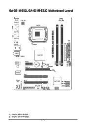
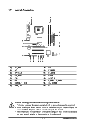
Only for GA-G31M-ES2L. GA-G31M-ES2L/GA-G31M-ES2C Motherboard Layout KB_MS ATX_12V LGA775 CPU_FAN COMA GA-G31M-ES2L/GA-G31M-ES2C DDRII1 DDRII2 PWR_LED F_PANEL LPT LAN VGA R_USB ATX IDE USB AUDIO F_AUDIO AR8131 AR8132 PCIE_1 PCIE_16 IT8718 PCI1 CODEC PCI2 CD_IN SPDIF_O FDD Intel® G31 BAT B_BIOS M_BIOS CLR_CMOS CI SYS_FAN F_USB1F_USB2 Intel® ICH7 SATAII3 SATAII2 SATAII1 SATAII0 Only for GA-G31M-ES2C. - 7 -
Only for GA-G31M-ES2L. GA-G31M-ES2L/GA-G31M-ES2C Motherboard Layout KB_MS ATX_12V LGA775 CPU_FAN COMA GA-G31M-ES2L/GA-G31M-ES2C DDRII1 DDRII2 PWR_LED F_PANEL LPT LAN VGA R_USB ATX IDE USB AUDIO F_AUDIO AR8131 AR8132 PCIE_1 PCIE_16 IT8718 PCI1 CODEC PCI2 CD_IN SPDIF_O FDD Intel® G31 BAT B_BIOS M_BIOS CLR_CMOS CI SYS_FAN F_USB1F_USB2 Intel® ICH7 SATAII3 SATAII2 SATAII1 SATAII0 Only for GA-G31M-ES2C. - 7 -
Manual
Page 9
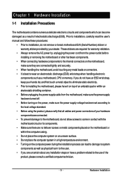
... result of the product, please consult a certified computer technician. - 9 - Hardware Installation Chapter 1 Hardware Installation 1-1 Installation Precautions The motherboard contains numerous delicate electronic circuits and components which can lead to damage to system components as well as physical harm to the user. &#... connectors. • It is best to wear an electrostatic discharge (ESD) wrist strap when handling electronic components such as a motherboard, CPU or memory. These stickers are required for warranty validation. • Always remove the AC power by your hands dry ...
... result of the product, please consult a certified computer technician. - 9 - Hardware Installation Chapter 1 Hardware Installation 1-1 Installation Precautions The motherboard contains numerous delicate electronic circuits and components which can lead to damage to system components as well as physical harm to the user. &#... connectors. • It is best to wear an electrostatic discharge (ESD) wrist strap when handling electronic components such as a motherboard, CPU or memory. These stickers are required for warranty validation. • Always remove the AC power by your hands dry ...
Manual
Page 10
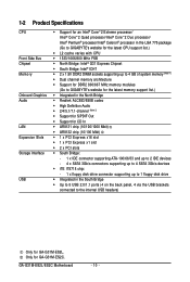
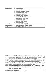
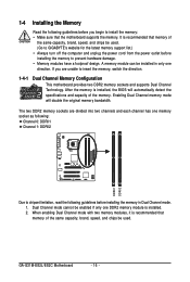
Only for GA-G31M-ES2L. GA-G31M-ES2L/ES2C Motherboard - 10 - 1-2 Product Specifications CPU Front Side Bus Chipset Memory ... processor/ Intel® Pentium® processor/Intel® Celeron® processor in the LGA 775 package (Go to GIGABYTE's website for the latest CPU support list.) L2 cache varies with CPU 1333/1066/800 MHz ... (Note 1) Dual channel memory architecture Support for DDR2 800/667 MHz memory modules (Go to GIGABYTE's website for the latest memory support list.) Integrated in the North Bridge Realtek ALC883/888B codec ...
Only for GA-G31M-ES2L. GA-G31M-ES2L/ES2C Motherboard - 10 - 1-2 Product Specifications CPU Front Side Bus Chipset Memory ... processor/ Intel® Pentium® processor/Intel® Celeron® processor in the LGA 775 package (Go to GIGABYTE's website for the latest CPU support list.) L2 cache varies with CPU 1333/1066/800 MHz ... (Note 1) Dual channel memory architecture Support for DDR2 800/667 MHz memory modules (Go to GIGABYTE's website for the latest memory support list.) Integrated in the North Bridge Realtek ALC883/888B codec ...
Manual
Page 12
.../ Celeron Dual-Core/ Celeron 400 Series CPU to enable support for system usage and therefore the actual memory size is reserved for Easy Energy Saver. GA-G31M-ES2L/ES2C Motherboard - 12 - For example, 4 GB of memory size will instead be shown as 3.xx GB during system startup. (Note 2) To configure 7.1-channel audio, you need...
.../ Celeron Dual-Core/ Celeron 400 Series CPU to enable support for system usage and therefore the actual memory size is reserved for Easy Energy Saver. GA-G31M-ES2L/ES2C Motherboard - 12 - For example, 4 GB of memory size will instead be shown as 3.xx GB during system startup. (Note 2) To configure 7.1-channel audio, you need...
Manual
Page 13
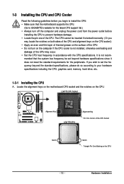
Locate the alignment keys on the motherboard CPU socket and the notches on the CPU - 13 - The CPU cannot be set the frequency beyond hardware specifications since it does not meet the ... for the latest CPU support list.) • Always turn on the computer if the CPU cooler is not recom- mended that the motherboard supports the CPU. (Go to GIGABYTE's website for the peripherals. LGA775 CPU Socket Alignment Key LGA 775 CPU Alignment Key Pin One Corner of the CPU Socket Notch Notch...
Locate the alignment keys on the motherboard CPU socket and the notches on the CPU - 13 - The CPU cannot be set the frequency beyond hardware specifications since it does not meet the ... for the latest CPU support list.) • Always turn on the computer if the CPU cooler is not recom- mended that the motherboard supports the CPU. (Go to GIGABYTE's website for the peripherals. LGA775 CPU Socket Alignment Key LGA 775 CPU Alignment Key Pin One Corner of the CPU Socket Notch Notch...
Manual
Page 14
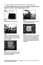
... from the CPU socket. (DO NOT touch socket contacts.) Step 3: Remove the protective socket cover from the power outlet to prevent damage to the CPU. GA-G31M-ES2L/ES2C Motherboard - 14 - Follow the steps below to turn off the computer and unplug the power cord from the load plate. (To protect the CPU socket...
... from the CPU socket. (DO NOT touch socket contacts.) Step 3: Remove the protective socket cover from the power outlet to prevent damage to the CPU. GA-G31M-ES2L/ES2C Motherboard - 14 - Follow the steps below to turn off the computer and unplug the power cord from the load plate. (To protect the CPU socket...
Manual
Page 15
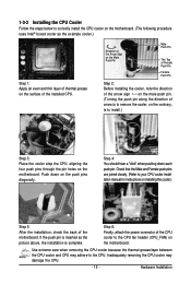
...sign on the male push pin. (Turning the push pin along the direction of the installed CPU. Step 6: Finally, attach the power connector of the motherboard. If the push pin is inserted as the example cooler.) Step 1: Apply an even and thin layer of thermal grease on the surface of arrow...for instructions on installing the cooler.) Step 5: After the installation, check the back of the CPU cooler to the CPU fan header (CPU_FAN) on the motherboard. Hardware Installation Push down each push pin. 1-3-2 Installing the CPU Cooler Follow the steps below to correctly install the CPU cooler on the...
...sign on the male push pin. (Turning the push pin along the direction of the installed CPU. Step 6: Finally, attach the power connector of the motherboard. If the push pin is inserted as the example cooler.) Step 1: Apply an even and thin layer of thermal grease on the surface of arrow...for instructions on installing the cooler.) Step 5: After the installation, check the back of the CPU cooler to the CPU fan header (CPU_FAN) on the motherboard. Hardware Installation Push down each push pin. 1-3-2 Installing the CPU Cooler Follow the steps below to correctly install the CPU cooler on the...
Manual
Page 16
... memory of the same capacity, brand, speed, and chips be used . (Go to GIGABYTE's website for the latest memory support list.) • Always turn off the computer and ...be used . When enabling Dual Channel mode with two memory modules, it is recommended that the motherboard supports the memory. The two DDR2 memory sockets are unable to insert the memory, switch the direction. 1-4-1 Dual... have a foolproof design. A memory module can be enabled if only one direction. GA-G31M-ES2L/ES2C Motherboard - 16 - Dual Channel mode cannot be installed in Dual Channel mode. 1.
... memory of the same capacity, brand, speed, and chips be used . (Go to GIGABYTE's website for the latest memory support list.) • Always turn off the computer and ...be used . When enabling Dual Channel mode with two memory modules, it is recommended that the motherboard supports the memory. The two DDR2 memory sockets are unable to insert the memory, switch the direction. 1-4-1 Dual... have a foolproof design. A memory module can be enabled if only one direction. GA-G31M-ES2L/ES2C Motherboard - 16 - Dual Channel mode cannot be installed in Dual Channel mode. 1.
Manual
Page 17
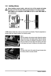
... memory sockets. DDR2 DIMMs are not compatible to DDR DIMMs. Be sure to install DDR2 DIMMs on the socket. Place the memory module on this motherboard. Notch DDR2 DIMM A DDR2 memory module has a notch, so it vertically into place when the memory module is securely inserted. - 17 - As indicated in the...
... memory sockets. DDR2 DIMMs are not compatible to DDR DIMMs. Be sure to install DDR2 DIMMs on the socket. Place the memory module on this motherboard. Notch DDR2 DIMM A DDR2 memory module has a notch, so it vertically into place when the memory module is securely inserted. - 17 - As indicated in the...
Manual
Page 18
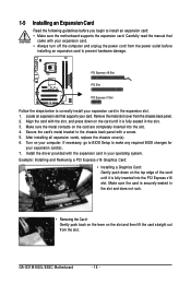
...Make sure the metal contacts on the card until it is fully inserted into the slot. 4. Install the driver provided with a screw. 5. GA-G31M-ES2L/ES2C Motherboard - 18 - Align the card with your expansion card in the slot. 3. After installing all expansion cards, replace the chassis cover(s). 6. ... an Expansion Card Read the following guidelines before installing an expansion card to install an expansion card: • Make sure the motherboard supports the expansion card. Locate an expansion slot that came with the slot, and press down on your card. Carefully read the...
...Make sure the metal contacts on the card until it is fully inserted into the slot. 4. Install the driver provided with a screw. 5. GA-G31M-ES2L/ES2C Motherboard - 18 - Align the card with your expansion card in the slot. 3. After installing all expansion cards, replace the chassis cover(s). 6. ... an Expansion Card Read the following guidelines before installing an expansion card to install an expansion card: • Make sure the motherboard supports the expansion card. Locate an expansion slot that came with the slot, and press down on your card. Carefully read the...
Manual
Page 19
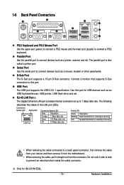
... of the LAN port LEDs. Only for USB devices such as a mouse, modem or other peripherals. Do not rock it straight out from the motherboard. • When removing the cable, pull it side to side to prevent an electrical short inside the cable connector. The parallel port is occurring ... to 1 Gbps data rate. Use this port. RJ-45 LAN Port The Gigabit Ethernet LAN port provides Internet connection at up to this port for GA-G31M-ES2L. - 19 - 1-6 Back Panel Connectors PS/2 Keyboard and PS/2 Mouse Port Use the upper port (green) to connect a PS/2 mouse and the lower port...
... of the LAN port LEDs. Only for USB devices such as a mouse, modem or other peripherals. Do not rock it straight out from the motherboard. • When removing the cable, pull it side to side to prevent an electrical short inside the cable connector. The parallel port is occurring ... to 1 Gbps data rate. Use this port. RJ-45 LAN Port The Gigabit Ethernet LAN port provides Internet connection at up to this port for GA-G31M-ES2L. - 19 - 1-6 Back Panel Connectors PS/2 Keyboard and PS/2 Mouse Port Use the upper port (green) to connect a PS/2 mouse and the lower port...
Manual
Page 20
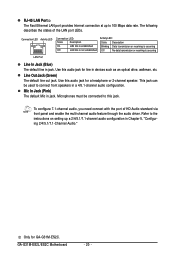
.... To configure 7.1-channel audio, you need connect with the port of the LAN port LEDs. Use this audio jack for GA-G31M-ES2C. This jack can be connected to 100 Mbps data rate. GA-G31M-ES2L/ES2C Motherboard - 20 - RJ-45 LAN Port The Fast Ethernet LAN port provides Internet connection at up a 2/4/5.1/7.1-channel audio configuration in...
.... To configure 7.1-channel audio, you need connect with the port of the LAN port LEDs. Use this audio jack for GA-G31M-ES2C. This jack can be connected to 100 Mbps data rate. GA-G31M-ES2L/ES2C Motherboard - 20 - RJ-45 LAN Port The Fast Ethernet LAN port provides Internet connection at up a 2/4/5.1/7.1-channel audio configuration in...
Manual
Page 21
..., make sure your devices are compliant with the connectors you wish to connect. • Before installing the devices, be sure to the connector on the motherboard. - 21 - Hardware Installation
..., make sure your devices are compliant with the connectors you wish to connect. • Before installing the devices, be sure to the connector on the motherboard. - 21 - Hardware Installation
Manual
Page 22
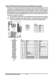
... -12V GND PS_ON(soft On/Off) GND GND GND -5V +5V +5V +5V (Only for 2x12-pin ATX) GND (Only for 2x12-pin ATX) GA-G31M-ES2L/ES2C Motherboard - 22 - To meet expansion requirements, it is not connected, the computer will not start. The 12V power connector mainly supplies power to the power connector...
... -12V GND PS_ON(soft On/Off) GND GND GND -5V +5V +5V +5V (Only for 2x12-pin ATX) GND (Only for 2x12-pin ATX) GA-G31M-ES2L/ES2C Motherboard - 22 - To meet expansion requirements, it is not connected, the computer will not start. The 12V power connector mainly supplies power to the power connector...

Manual
Page 23
The motherboard supports CPU fan speed control, which requires the use of different color. 33 1 34 2 - 23 - Most fan headers possess a foolproof insertion design. When connecting a fan ... supported are not configuration jumper blocks. Before connecting a floppy disk drive, be sure to connect it is the ground wire). 3/4) CPU_FAN/SYS_FAN (Fan Headers) The motherboard has a 4-pin CPU fan header (CPU_FAN) and a 3-pin (SYS_FAN) system fan header. For optimum heat dissipation, it in damage to connect a floppy disk drive. Hardware...
The motherboard supports CPU fan speed control, which requires the use of different color. 33 1 34 2 - 23 - Most fan headers possess a foolproof insertion design. When connecting a fan ... supported are not configuration jumper blocks. Before connecting a floppy disk drive, be sure to connect it is the ground wire). 3/4) CPU_FAN/SYS_FAN (Fan Headers) The motherboard has a 4-pin CPU fan header (CPU_FAN) and a 3-pin (SYS_FAN) system fan header. For optimum heat dissipation, it in damage to connect a floppy disk drive. Hardware...


