Manual
Page 4
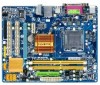
... ...6 OptionalItems...6 GA-G31M-ES2L/GA-G31M-ES2C Motherboard Layout 7 Block Diagram...8 Chapter 1 Hardware Installation 9 1-1 Installation Precautions 9 1-2 Product Specifications 10 1-3 Installing the CPU and CPU Cooler 13 1-3-1 Installing the CPU 13 1-3-2 Installing the CPU Cooler 15 1-4 Installing the Memory 16 1-4-1 Dual Channel Memory Configuration 16 1-4-2 Installing a Memory 17 1-5 Installing an Expansion Card 18 1-6 Back Panel Connectors 19...
... ...6 OptionalItems...6 GA-G31M-ES2L/GA-G31M-ES2C Motherboard Layout 7 Block Diagram...8 Chapter 1 Hardware Installation 9 1-1 Installation Precautions 9 1-2 Product Specifications 10 1-3 Installing the CPU and CPU Cooler 13 1-3-1 Installing the CPU 13 1-3-2 Installing the CPU Cooler 15 1-4 Installing the Memory 16 1-4-1 Dual Channel Memory Configuration 16 1-4-2 Installing a Memory 17 1-5 Installing an Expansion Card 18 1-6 Back Panel Connectors 19...
Manual
Page 10
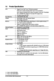
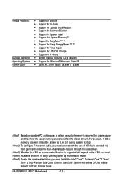
...supporting up to 4 GB of system memory (Note 1) Dual channel memory architecture Support for DDR2 800/667 MHz memory modules (Go to GIGABYTE's website for the latest memory support list.) Integrated in the North Bridge Realtek ALC883/888B codec High Definition Audio ...x floppy disk drive connector supporting up to 1 floppy disk drive Integrated in the South Bridge Up to 8 USB 2.0/1.1 ports (4 on the back panel, 4 via the USB brackets connected to the internal USB headers) Only for GA-G31M-ES2C. Only for GA-G31M-ES2L.
...supporting up to 4 GB of system memory (Note 1) Dual channel memory architecture Support for DDR2 800/667 MHz memory modules (Go to GIGABYTE's website for the latest memory support list.) Integrated in the North Bridge Realtek ALC883/888B codec High Definition Audio ...x floppy disk drive connector supporting up to 1 floppy disk drive Integrated in the South Bridge Up to 8 USB 2.0/1.1 ports (4 on the back panel, 4 via the USB brackets connected to the internal USB headers) Only for GA-G31M-ES2C. Only for GA-G31M-ES2L.
Manual
Page 11
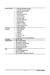
... IDE connector 4 x SATA 3Gb/s connectors 1 x CPU fan header 1 x system fan header 1 x front panel header 1 x front panel audio header 1 x CD In connector 1 x S/PDIF Out header 2 x USB 2.0/1.1 headers 1 x chassis... intrusion header 1 x power LED header Back Panel 1 x PS/2 keyboard port Connectors 1 x PS/2 mouse port 1 x parallel port 1 x serial port 1...
... IDE connector 4 x SATA 3Gb/s connectors 1 x CPU fan header 1 x system fan header 1 x front panel header 1 x front panel audio header 1 x CD In connector 1 x S/PDIF Out header 2 x USB 2.0/1.1 headers 1 x chassis... intrusion header 1 x power LED header Back Panel 1 x PS/2 keyboard port Connectors 1 x PS/2 mouse port 1 x parallel port 1 x serial port 1...
Manual
Page 12
... of HD Audio standard via front panel and enable the multi-channel audio feature through the audio driver. (Note 3) Whether the CPU fan speed control function is supported will depend on standard PC architecture, a certain amount of memory is reserved for Easy Energy Saver. GA-G31M-ES2L/ES2C Motherboard - 12 - Unique Features Bundled Software...
... of HD Audio standard via front panel and enable the multi-channel audio feature through the audio driver. (Note 3) Whether the CPU fan speed control function is supported will depend on standard PC architecture, a certain amount of memory is reserved for Easy Energy Saver. GA-G31M-ES2L/ES2C Motherboard - 12 - Unique Features Bundled Software...
Manual
Page 18
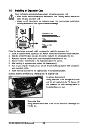
Secure the card's metal bracket to the chassis back panel with your expansion card. • Always turn off the computer and unplug the power cord from the power outlet before you begin to make any required BIOS changes for your expansion card(s). 7. GA-G31M-ES2L/ES2C Motherboard - 18 - 1-5 Installing an Expansion Card Read the following..., and press down on your card. Make sure the metal contacts on the slot and then lift the card straight out from the chassis back panel. 2. PCI Express x16 Slot PCI Slot PCI Express x1 Slot Follow the steps below to prevent hardware damage.
Secure the card's metal bracket to the chassis back panel with your expansion card. • Always turn off the computer and unplug the power cord from the power outlet before you begin to make any required BIOS changes for your expansion card(s). 7. GA-G31M-ES2L/ES2C Motherboard - 18 - 1-5 Installing an Expansion Card Read the following..., and press down on your card. Make sure the metal contacts on the slot and then lift the card straight out from the chassis back panel. 2. PCI Express x16 Slot PCI Slot PCI Express x1 Slot Follow the steps below to prevent hardware damage.
Manual
Page 19
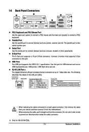
... port. Do not rock it straight out from the motherboard. • When removing the cable, pull it side to side to a back panel connector, first remove the cable from your device and then remove it from the connector. The parallel port is occurring • When removing the... cable connected to prevent an electrical short inside the cable connector. Serial Port Use the serial port to this port for GA-G31M-ES2L. - 19 - Hardware Installation 1-6 Back Panel Connectors PS/2 Keyboard and PS/2 Mouse Port Use the upper port (green) to connect a PS/2 mouse and the lower ...
... port. Do not rock it straight out from the motherboard. • When removing the cable, pull it side to side to a back panel connector, first remove the cable from your device and then remove it from the connector. The parallel port is occurring • When removing the... cable connected to prevent an electrical short inside the cable connector. Serial Port Use the serial port to this port for GA-G31M-ES2L. - 19 - Hardware Installation 1-6 Back Panel Connectors PS/2 Keyboard and PS/2 Mouse Port Use the upper port (green) to connect a PS/2 mouse and the lower ...
Manual
Page 20
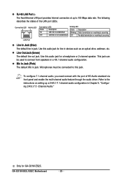
...channel speaker. This jack can be connected to connect front speakers in a 4/5.1-channel audio configuration. Microphones must be used to this jack. GA-G31M-ES2L/ES2C Motherboard - 20 - To configure 7.1-channel audio, you need connect with the port of the LAN port LEDs. Only for line in ...out jack. Use this audio jack for GA-G31M-ES2C. Mic In Jack (Pink) The default Mic in Chapter 5, "Configuring 2/4/5.1/7.1-Channel Audio." Refer to 100 Mbps data rate. The following describes the states of HD Audio standard via front panel and enable the multi-channel audio feature ...
...channel speaker. This jack can be connected to connect front speakers in a 4/5.1-channel audio configuration. Microphones must be used to this jack. GA-G31M-ES2L/ES2C Motherboard - 20 - To configure 7.1-channel audio, you need connect with the port of the LAN port LEDs. Only for line in ...out jack. Use this audio jack for GA-G31M-ES2C. Mic In Jack (Pink) The default Mic in Chapter 5, "Configuring 2/4/5.1/7.1-Channel Audio." Refer to 100 Mbps data rate. The following describes the states of HD Audio standard via front panel and enable the multi-channel audio feature ...
Manual
Page 26
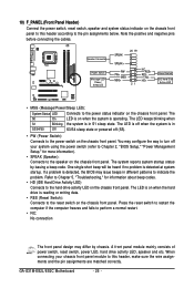
... the computer freezes and fails to perform a normal restart. • NC: No connection The front panel design may issue beeps in different patterns to the reset switch on the chassis front panel. GA-G31M-ES2L/ES2C Motherboard - 26 - If a problem is in S1 sleep state. Speaker Connector Power Switch Message LED... Disk Active LED • MSG (Message/Power/Sleep LED): System Status LED Connects to the power status indicator on the chassis front panel to this header, make sure the wire assignments and the pin assignments are matched correctly. The LED is off when the system is ...
... the computer freezes and fails to perform a normal restart. • NC: No connection The front panel design may issue beeps in different patterns to the reset switch on the chassis front panel. GA-G31M-ES2L/ES2C Motherboard - 26 - If a problem is in S1 sleep state. Speaker Connector Power Switch Message LED... Disk Active LED • MSG (Message/Power/Sleep LED): System Status LED Connects to the power status indicator on the chassis front panel to this header, make sure the wire assignments and the pin assignments are matched correctly. The LED is off when the system is ...
Manual
Page 27
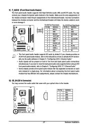
... signals will make the device unable to Chapter 5, "Configuring 2/4/5.1/7.1-Channel Audio." • Some chassis provide a front panel audio module that came with your chassis front panel audio module to the header. 1 Pin No. You may connect the audio cable that has separated connectors on both... of the motherboard header. For information about connecting the front panel audio module that has different wire assignments, please contact the chassis manufacturer. 12) CD_IN (CD In Connector) You may connect...
... signals will make the device unable to Chapter 5, "Configuring 2/4/5.1/7.1-Channel Audio." • Some chassis provide a front panel audio module that came with your chassis front panel audio module to the header. 1 Pin No. You may connect the audio cable that has separated connectors on both... of the motherboard header. For information about connecting the front panel audio module that has different wire assignments, please contact the chassis manufacturer. 12) CD_IN (CD In Connector) You may connect...
Manual
Page 69
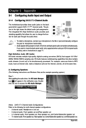
... for microphone functionality. • Audio signals will appear in and out) to be present on both of the front and back panel audio connections simultaneously. Line In Front Speaker Out Mic In • To install a microphone, connect your microphone to the following instructions... (HD Audio) HD Audio includes multiple high quality digital-to-analog converters (DACs) that allows the user to instructions on the back panel which support 2/4/5.1/7.1(Note)-channel audio. The integrated HD (High Definition) audio provides jack retasking capability that support 44.1KHz/ 48KHz/ 96KHz...
... for microphone functionality. • Audio signals will appear in and out) to be present on both of the front and back panel audio connections simultaneously. Line In Front Speaker Out Mic In • To install a microphone, connect your microphone to the following instructions... (HD Audio) HD Audio includes multiple high quality digital-to-analog converters (DACs) that allows the user to instructions on the back panel which support 2/4/5.1/7.1(Note)-channel audio. The integrated HD (High Definition) audio provides jack retasking capability that support 44.1KHz/ 48KHz/ 96KHz...
Manual
Page 71
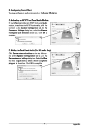
...C. Click OK to complete. B. Select the Mute the rear output device, when a front headphone plugged in check box. Muting the Back Panel Audio (For HD Audio Only): Click Device advanced settings on the top right corner on the Sound Effects tab. Appendix On the Connector Settings ...dialog box, select the Disable front panel jack detection check box. Click OK to complete. - 71 - D. Activating an AC'97 Front Panel Audio Module: If your chassis provides an AC'97 front panel audio module, to open the Device advanced settings dialog box.
...C. Click OK to complete. B. Select the Mute the rear output device, when a front headphone plugged in check box. Muting the Back Panel Audio (For HD Audio Only): Click Device advanced settings on the top right corner on the Sound Effects tab. Appendix On the Connector Settings ...dialog box, select the Disable front panel jack detection check box. Click OK to complete. - 71 - D. Activating an AC'97 Front Panel Audio Module: If your chassis provides an AC'97 front panel audio module, to open the Device advanced settings dialog box.

Manual
Page 72
... S/PDIF out: The S/PDIF Out jacks can transmit audio signals to an external decoder for decoding to the SPDIF_O header on your motherboard. GA-G31M-ES2L/ES2C Motherboard - 72 - Install the S/PDIF in damage to the device. Incorrect connection may render the device unusable or even result in and out... cable first if you want to output S/PDIF digital audio signals to the chassis back panel with pin 1 of the S/PDIF out cable must align ...
... S/PDIF out: The S/PDIF Out jacks can transmit audio signals to an external decoder for decoding to the SPDIF_O header on your motherboard. GA-G31M-ES2L/ES2C Motherboard - 72 - Install the S/PDIF in damage to the device. Incorrect connection may render the device unusable or even result in and out... cable first if you want to output S/PDIF digital audio signals to the chassis back panel with pin 1 of the S/PDIF out cable must align ...
Manual
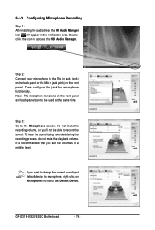
Page 74
...to the Microphone screen. Step 2: Connect your microphone to the Mic in jack (pink) on the back panel or the Mic in the notification area. If you set the volumes at the same time. Note: The microphone functions... on the front panel and back panel cannot be able to microphone, right-click on the front panel. Then configure the jack for microphone functionality. It is recommended that you want to... Audio Manager icon will appear in jack (pink) on Microphone and select Set Default Device. GA-G31M-ES2L/ES2C Motherboard - 74 -
...to the Microphone screen. Step 2: Connect your microphone to the Mic in jack (pink) on the back panel or the Mic in the notification area. If you set the volumes at the same time. Note: The microphone functions... on the front panel and back panel cannot be able to microphone, right-click on the front panel. Then configure the jack for microphone functionality. It is recommended that you want to... Audio Manager icon will appear in jack (pink) on Microphone and select Set Default Device. GA-G31M-ES2L/ES2C Motherboard - 74 -


