Manual
Page 1
GA-G31M-ES2L/ GA-G31M-ES2C LGA775 socket motherboard for Intel® CoreTM processor family/ Intel® Pentium® processor family/Intel® Celeron® processor family User's Manual Rev. 2301 12ME-G31MES2L-2301R
GA-G31M-ES2L/ GA-G31M-ES2C LGA775 socket motherboard for Intel® CoreTM processor family/ Intel® Pentium® processor family/Intel® Celeron® processor family User's Manual Rev. 2301 12ME-G31MES2L-2301R
Manual
Page 2
Motherboard GA-G31M-ES2L/GA-G31M-ES2C May 20, 2010 Motherboard GA-G31M-ES2L/ GA-G31M-ES2C May 20, 2010
Motherboard GA-G31M-ES2L/GA-G31M-ES2C May 20, 2010 Motherboard GA-G31M-ES2L/ GA-G31M-ES2C May 20, 2010

Manual
Page 3
... information, check on our website at: http://www.gigabyte.com.tw Identifying Your Motherboard Revision The revision number on your motherboard revision before updating motherboard BIOS, drivers, or when looking for technical information. Check your motherboard looks like this manual may be made by any ... Changes to their respective owners. Documentation Classifications In order to use of GIGABYTE. All rights reserved. No part of this product, GIGABYTE provides the following types of the motherboard is the property of this manual may be reproduced, copied, translated, ...
... information, check on our website at: http://www.gigabyte.com.tw Identifying Your Motherboard Revision The revision number on your motherboard revision before updating motherboard BIOS, drivers, or when looking for technical information. Check your motherboard looks like this manual may be made by any ... Changes to their respective owners. Documentation Classifications In order to use of GIGABYTE. All rights reserved. No part of this product, GIGABYTE provides the following types of the motherboard is the property of this manual may be reproduced, copied, translated, ...
Manual
Page 4
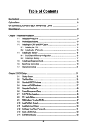
Table of Contents Box Contents ...6 OptionalItems...6 GA-G31M-ES2L/GA-G31M-ES2C Motherboard Layout 7 Block Diagram...8 Chapter 1 Hardware Installation 9 1-1 Installation Precautions 9 1-2 Product Specifications 10 1-3 Installing the CPU and CPU Cooler 13 1-3-1 Installing the CPU 13 1-3-2 Installing the CPU ...
Table of Contents Box Contents ...6 OptionalItems...6 GA-G31M-ES2L/GA-G31M-ES2C Motherboard Layout 7 Block Diagram...8 Chapter 1 Hardware Installation 9 1-1 Installation Precautions 9 1-2 Product Specifications 10 1-3 Installing the CPU and CPU Cooler 13 1-3-1 Installing the CPU 13 1-3-2 Installing the CPU ...
Manual
Page 6
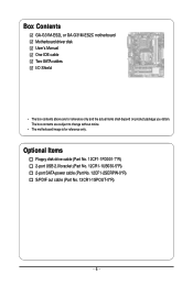
Optional Items Floppy disk drive cable (Part No. 12CF1-1FD001-7*R) 2-port USB 2.0 bracket (Part No. 12CR1-1UB030-5*R) 2-port SATA power cable (Part No. 12CF1-2SERPW-0*R) S/PDIF out cable (Part No. 12CR1-1SPOUT-0*R) - 6 - The box contents are for reference only. Box Contents GA-G31M-ES2L or GA-G31M-ES2C motherboard Motherboard driver disk User's Manual One IDE cable Two SATA cables I/O Shield • The box contents above are subject to change without notice. • The motherboard image is for reference only and the actual items shall depend on product package you obtain.
Optional Items Floppy disk drive cable (Part No. 12CF1-1FD001-7*R) 2-port USB 2.0 bracket (Part No. 12CR1-1UB030-5*R) 2-port SATA power cable (Part No. 12CF1-2SERPW-0*R) S/PDIF out cable (Part No. 12CR1-1SPOUT-0*R) - 6 - The box contents are for reference only. Box Contents GA-G31M-ES2L or GA-G31M-ES2C motherboard Motherboard driver disk User's Manual One IDE cable Two SATA cables I/O Shield • The box contents above are subject to change without notice. • The motherboard image is for reference only and the actual items shall depend on product package you obtain.
Manual
Page 7
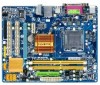
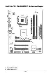
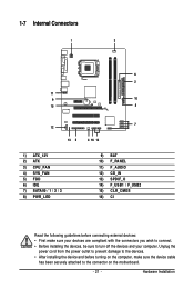
Only for GA-G31M-ES2L. GA-G31M-ES2L/GA-G31M-ES2C Motherboard Layout KB_MS ATX_12V LGA775 CPU_FAN COMA GA-G31M-ES2L/GA-G31M-ES2C DDRII1 DDRII2 PWR_LED F_PANEL LPT LAN VGA R_USB ATX IDE USB AUDIO F_AUDIO AR8131 AR8132 PCIE_1 PCIE_16 IT8718 PCI1 CODEC PCI2 CD_IN SPDIF_O FDD Intel® G31 BAT B_BIOS M_BIOS CLR_CMOS CI SYS_FAN F_USB1F_USB2 Intel® ICH7 SATAII3 SATAII2 SATAII1 SATAII0 Only for GA-G31M-ES2C. - 7 -
Only for GA-G31M-ES2L. GA-G31M-ES2L/GA-G31M-ES2C Motherboard Layout KB_MS ATX_12V LGA775 CPU_FAN COMA GA-G31M-ES2L/GA-G31M-ES2C DDRII1 DDRII2 PWR_LED F_PANEL LPT LAN VGA R_USB ATX IDE USB AUDIO F_AUDIO AR8131 AR8132 PCIE_1 PCIE_16 IT8718 PCI1 CODEC PCI2 CD_IN SPDIF_O FDD Intel® G31 BAT B_BIOS M_BIOS CLR_CMOS CI SYS_FAN F_USB1F_USB2 Intel® ICH7 SATAII3 SATAII2 SATAII1 SATAII0 Only for GA-G31M-ES2C. - 7 -
Manual
Page 9
... required for warranty validation. • Always remove the AC power by your dealer. Chapter 1 Hardware Installation 1-1 Installation Precautions The motherboard contains numerous delicate electronic circuits and components which can become damaged as a result of an antistatic pad or within an electrostatic shielding ...container. • Before unplugging the power supply cable from the motherboard, make sure the power supply has been turned off. • Before turning on the computer power during the installation process...
... required for warranty validation. • Always remove the AC power by your dealer. Chapter 1 Hardware Installation 1-1 Installation Precautions The motherboard contains numerous delicate electronic circuits and components which can become damaged as a result of an antistatic pad or within an electrostatic shielding ...container. • Before unplugging the power supply cable from the motherboard, make sure the power supply has been turned off. • Before turning on the computer power during the installation process...
Manual
Page 10
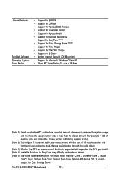
GA-G31M-ES2L/ES2C Motherboard - 10 - Only for GA-G31M-ES2L. 1-2 Product Specifications CPU Front Side Bus Chipset Memory Onboard Graphics Audio LAN Expansion Slots Storage Interface USB Support for an Intel® CoreTM 2 ... sockets supporting up to 4 GB of system memory (Note 1) Dual channel memory architecture Support for DDR2 800/667 MHz memory modules (Go to GIGABYTE's website for the latest memory support list.) Integrated in the North Bridge Realtek ALC883/888B codec High Definition Audio 2/4/5.1/7.1-channel (Note...
GA-G31M-ES2L/ES2C Motherboard - 10 - Only for GA-G31M-ES2L. 1-2 Product Specifications CPU Front Side Bus Chipset Memory Onboard Graphics Audio LAN Expansion Slots Storage Interface USB Support for an Intel® CoreTM 2 ... sockets supporting up to 4 GB of system memory (Note 1) Dual channel memory architecture Support for DDR2 800/667 MHz memory modules (Go to GIGABYTE's website for the latest memory support list.) Integrated in the North Bridge Realtek ALC883/888B codec High Definition Audio 2/4/5.1/7.1-channel (Note...
Manual
Page 12
.../XP Micro ATX form factor; 24.4cm x 19.4cm (Note 1) Based on the CPU you install. (Note 4) Available functions in EasyTune may differ by motherboard model. (Note 5) Due to the hardware limitation, you must install the Intel® CoreTM 2 Extreme/ CoreTM 2 Quad/ CoreTM 2 Duo/ Pentium Dual-Core/ Celeron Dual-Core... the stated amount. For example, 4 GB of memory size will depend on standard PC architecture, a certain amount of memory is reserved for Easy Energy Saver. GA-G31M-ES2L/ES2C Motherboard - 12 -
.../XP Micro ATX form factor; 24.4cm x 19.4cm (Note 1) Based on the CPU you install. (Note 4) Available functions in EasyTune may differ by motherboard model. (Note 5) Due to the hardware limitation, you must install the Intel® CoreTM 2 Extreme/ CoreTM 2 Quad/ CoreTM 2 Duo/ Pentium Dual-Core/ Celeron Dual-Core... the stated amount. For example, 4 GB of memory size will depend on standard PC architecture, a certain amount of memory is reserved for Easy Energy Saver. GA-G31M-ES2L/ES2C Motherboard - 12 -
Manual
Page 13
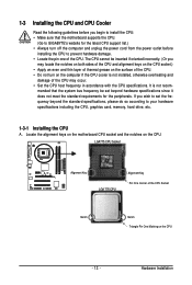
... may occur. • Set the CPU host frequency in accordance with the CPU specifications. mended that the motherboard supports the CPU. (Go to GIGABYTE's website for the peripherals. Locate the alignment keys on the motherboard CPU socket and the notches on the computer if the CPU cooler is not recom- 1-3 Installing the CPU...
... may occur. • Set the CPU host frequency in accordance with the CPU specifications. mended that the motherboard supports the CPU. (Go to GIGABYTE's website for the peripherals. Locate the alignment keys on the motherboard CPU socket and the notches on the computer if the CPU cooler is not recom- 1-3 Installing the CPU...
Manual
Page 14
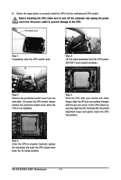
... the protective socket cover when the CPU is properly inserted, replace the load plate and push the CPU socket lever back into its locked position. GA-G31M-ES2L/ES2C Motherboard - 14 - Step 2: Lift the metal load plate from the CPU socket. (DO NOT touch socket contacts.) Step 3: Remove the protective socket .... Step 5: Once the CPU is not installed.) Step 4: Hold the CPU with the socket alignment keys) and gently insert the CPU into the motherboard CPU socket. CPU Socket Lever Step 1: Completely raise the CPU socket lever. Follow the steps below to the CPU. Align the CPU pin one ...
... the protective socket cover when the CPU is properly inserted, replace the load plate and push the CPU socket lever back into its locked position. GA-G31M-ES2L/ES2C Motherboard - 14 - Step 2: Lift the metal load plate from the CPU socket. (DO NOT touch socket contacts.) Step 3: Remove the protective socket .... Step 5: Once the CPU is not installed.) Step 4: Hold the CPU with the socket alignment keys) and gently insert the CPU into the motherboard CPU socket. CPU Socket Lever Step 1: Completely raise the CPU socket lever. Follow the steps below to the CPU. Align the CPU pin one ...
Manual
Page 15
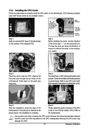
1-3-2 Installing the CPU Cooler Follow the steps below to correctly install the CPU cooler on the motherboard. (The following procedure uses Intel® boxed cooler as the picture above, the installation is to install.) Step 3: Place the cooler atop the CPU, aligning ...the four push pins through the pin holes on the motherboard. Direction of the Arrow Sign on the Male Push Pin Male Push Pin The Top of Female Push Pin Female Push Pin Step 2: Before installing...
1-3-2 Installing the CPU Cooler Follow the steps below to correctly install the CPU cooler on the motherboard. (The following procedure uses Intel® boxed cooler as the picture above, the installation is to install.) Step 3: Place the cooler atop the CPU, aligning ...the four push pins through the pin holes on the motherboard. Direction of the Arrow Sign on the Male Push Pin Male Push Pin The Top of Female Push Pin Female Push Pin Step 2: Before installing...
Manual
Page 16
... to GIGABYTE's website for the latest memory support list.) • Always turn off the computer and unplug the power cord from the power outlet before installing the memory in only one DDR2 memory module is installed, the BIOS will double the original memory bandwidth. Dual Channel mode cannot be used . GA-G31M-ES2L/ES2C Motherboard...
... to GIGABYTE's website for the latest memory support list.) • Always turn off the computer and unplug the power cord from the power outlet before installing the memory in only one DDR2 memory module is installed, the BIOS will double the original memory bandwidth. Dual Channel mode cannot be used . GA-G31M-ES2L/ES2C Motherboard...
Manual
Page 17
... , make sure to turn off the computer and unplug the power cord from the power outlet to prevent damage to install DDR2 DIMMs on this motherboard. Follow the steps below to correctly install your fingers on the top edge of the memory socket. Spread the retaining clips at both ends of...
... , make sure to turn off the computer and unplug the power cord from the power outlet to prevent damage to install DDR2 DIMMs on this motherboard. Follow the steps below to correctly install your fingers on the top edge of the memory socket. Spread the retaining clips at both ends of...
Manual
Page 18
...slot and then lift the card straight out from the chassis back panel. 2. Carefully read the manual that supports your expansion card(s). 7. GA-G31M-ES2L/ES2C Motherboard - 18 - Remove the metal slot cover from the slot. Secure the card's metal bracket to install an expansion card: • Make ...sure the motherboard supports the expansion card. Make sure the metal contacts on your operating system. Turn on the card are completely inserted...
...slot and then lift the card straight out from the chassis back panel. 2. Carefully read the manual that supports your expansion card(s). 7. GA-G31M-ES2L/ES2C Motherboard - 18 - Remove the metal slot cover from the slot. Secure the card's metal bracket to install an expansion card: • Make ...sure the motherboard supports the expansion card. Make sure the metal contacts on your operating system. Turn on the card are completely inserted...
Manual
Page 19
... D-Sub port supports a 15-pin D-Sub connector. Use this port. Do not rock it straight out from the motherboard. • When removing the cable, pull it side to side to this port for GA-G31M-ES2L. - 19 - Connect a monitor that supports D-Sub connection to prevent an electrical short inside the cable connector. Hardware...
... D-Sub port supports a 15-pin D-Sub connector. Use this port. Do not rock it straight out from the motherboard. • When removing the cable, pull it side to side to this port for GA-G31M-ES2L. - 19 - Connect a monitor that supports D-Sub connection to prevent an electrical short inside the cable connector. Hardware...
Manual
Page 20
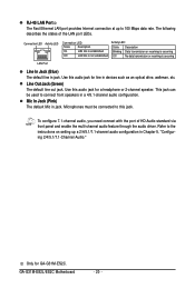
Use this audio jack for GA-G31M-ES2C. To configure 7.1-channel audio, you need connect with the port of the LAN port LEDs. Only for a headphone or 2-channel speaker. GA-G31M-ES2L/ES2C Motherboard - 20 - Use this jack. This jack can be connected to connect front speakers in a 4/5.1-channel audio configuration. Microphones must be used to this audio...
Use this audio jack for GA-G31M-ES2C. To configure 7.1-channel audio, you need connect with the port of the LAN port LEDs. Only for a headphone or 2-channel speaker. GA-G31M-ES2L/ES2C Motherboard - 20 - Use this jack. This jack can be connected to connect front speakers in a 4/5.1-channel audio configuration. Microphones must be used to this audio...
Manual
Page 21
..., make sure your devices are compliant with the connectors you wish to connect. • Before installing the devices, be sure to the connector on the motherboard. - 21 - Hardware Installation Unplug the power cord from the power outlet to prevent damage to the devices. • After installing the device and before connecting...
..., make sure your devices are compliant with the connectors you wish to connect. • Before installing the devices, be sure to the connector on the motherboard. - 21 - Hardware Installation Unplug the power cord from the power outlet to prevent damage to the devices. • After installing the device and before connecting...
Manual
Page 22
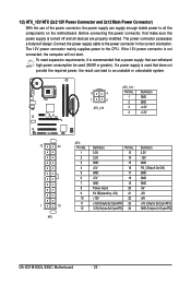
... PS_ON(soft On/Off) GND GND GND -5V +5V +5V +5V (Only for 2x12-pin ATX) GND (Only for 2x12-pin ATX) GA-G31M-ES2L/ES2C Motherboard - 22 - Connect the power supply cable to the CPU. The power connector possesses a foolproof design. To meet expansion requirements, it is turned ...off and all the components on the motherboard. Before connecting the power connector, first make sure the power supply is recommended that a power ...
... PS_ON(soft On/Off) GND GND GND -5V +5V +5V +5V (Only for 2x12-pin ATX) GND (Only for 2x12-pin ATX) GA-G31M-ES2L/ES2C Motherboard - 22 - Connect the power supply cable to the CPU. The power connector possesses a foolproof design. To meet expansion requirements, it is turned ...off and all the components on the motherboard. Before connecting the power connector, first make sure the power supply is recommended that a power ...

Manual
Page 23
... the CPU or the system may hang. • These fan headers are : 360 KB, 720 KB, 1.2 MB, 1.44 MB, and 2.88 MB. The motherboard supports CPU fan speed control, which requires the use of different color. 33 1 34 2 - 23 - Do not place a jumper cap on the headers. 5)...system fan be sure to connect it is typically designated by a stripe of a CPU fan with fan speed control design. 3/4) CPU_FAN/SYS_FAN (Fan Headers) The motherboard has a 4-pin CPU fan header (CPU_FAN) and a 3-pin (SYS_FAN) system fan header. For optimum heat dissipation, it in damage to connect a floppy disk...
... the CPU or the system may hang. • These fan headers are : 360 KB, 720 KB, 1.2 MB, 1.44 MB, and 2.88 MB. The motherboard supports CPU fan speed control, which requires the use of different color. 33 1 34 2 - 23 - Do not place a jumper cap on the headers. 5)...system fan be sure to connect it is typically designated by a stripe of a CPU fan with fan speed control design. 3/4) CPU_FAN/SYS_FAN (Fan Headers) The motherboard has a 4-pin CPU fan header (CPU_FAN) and a 3-pin (SYS_FAN) system fan header. For optimum heat dissipation, it in damage to connect a floppy disk...


