Manual
Page 4
Table of Contents Box Contents ...6 OptionalItems ...6 GA-G31-S3G Motherboard Layout 7 Block Diagram ...8 Chapter 1 Hardware Installation 9 1-1 Installation Precautions 9 1-2 Product Specifications 10 1-3 Installing the CPU and CPU Cooler 13 1-3-1 Installing the CPU 13 1-3-2 Installing the CPU Cooler 15 1-4 Installing the Memory 16 1-4-1 Dual Channel Memory Configuration 16 1-4-2 Installing a Memory 17 1-5 Installing an Expansion Card 18 1-6 Back Panel Connectors 19...
Table of Contents Box Contents ...6 OptionalItems ...6 GA-G31-S3G Motherboard Layout 7 Block Diagram ...8 Chapter 1 Hardware Installation 9 1-1 Installation Precautions 9 1-2 Product Specifications 10 1-3 Installing the CPU and CPU Cooler 13 1-3-1 Installing the CPU 13 1-3-2 Installing the CPU Cooler 15 1-4 Installing the Memory 16 1-4-1 Dual Channel Memory Configuration 16 1-4-2 Installing a Memory 17 1-5 Installing an Expansion Card 18 1-6 Back Panel Connectors 19...
Manual
Page 8
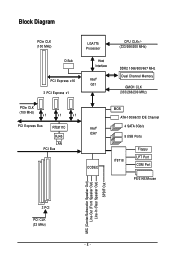
Block Diagram PCIe CLK (100 MHz) D-Sub PCI Express x16 3 PCI Express x1 LGA775 Processor Host Interface Intel® G31 CPU CLK+/(333/266/200 MHz) DDR2 1066/800/667 MHz Dual Channel Memory GMCH CLK (333/266/200 MHz) PCIe CLK (100 MHz) x1 x1 x1 PCI Express Bus RTL8111C RJ45 LAN PCI Bus Intel® ICH7 CODEC BIOS ATA-100/66/33 IDE Channel 4 SATA 3Gb/s 8 USB Ports IT8718 Floppy LPT Port COM Port PS/2 KB/Mouse MIC (Center/Subwoofer Speaker Out) Line-Out (Front Speaker Out) Line-In (Rear Speaker Out) SPDIF Out 3 PCI PCI CLK (33 MHz) - 8 -
Block Diagram PCIe CLK (100 MHz) D-Sub PCI Express x16 3 PCI Express x1 LGA775 Processor Host Interface Intel® G31 CPU CLK+/(333/266/200 MHz) DDR2 1066/800/667 MHz Dual Channel Memory GMCH CLK (333/266/200 MHz) PCIe CLK (100 MHz) x1 x1 x1 PCI Express Bus RTL8111C RJ45 LAN PCI Bus Intel® ICH7 CODEC BIOS ATA-100/66/33 IDE Channel 4 SATA 3Gb/s 8 USB Ports IT8718 Floppy LPT Port COM Port PS/2 KB/Mouse MIC (Center/Subwoofer Speaker Out) Line-Out (Front Speaker Out) Line-In (Rear Speaker Out) SPDIF Out 3 PCI PCI CLK (33 MHz) - 8 -
Manual
Page 9
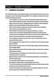
... other hardware components. • When connecting hardware components to the internal connectors on the computer power during the installation process can become damaged as a motherboard, CPU or memory. Prior to installation, carefully read the user's manual and follow these procedures: • Prior to installation, do not allow screws to wear an...
... other hardware components. • When connecting hardware components to the internal connectors on the computer power during the installation process can become damaged as a motherboard, CPU or memory. Prior to installation, carefully read the user's manual and follow these procedures: • Prior to installation, do not allow screws to wear an...
Manual
Page 10
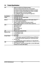
...® 4 processor/ Intel® Celeron® processor in the LGA 775 package (Go to GIGABYTE's website for the latest CPU support list.) L2 cache varies with CPU 1333/1066/800 MHz FSB North Bridge: Intel® G31 Express Chipset South Bridge: Intel® ICH7 2 x 1.8V DDR2 DIMM sockets supporting... Integrated in the South Bridge Up to 8 USB 2.0/1.1 ports (4 on the back panel, 4 via the USB brackets connected to the internal USB headers) GA-G31-S3G Motherboard - 10 -
...® 4 processor/ Intel® Celeron® processor in the LGA 775 package (Go to GIGABYTE's website for the latest CPU support list.) L2 cache varies with CPU 1333/1066/800 MHz FSB North Bridge: Intel® G31 Express Chipset South Bridge: Intel® ICH7 2 x 1.8V DDR2 DIMM sockets supporting... Integrated in the South Bridge Up to 8 USB 2.0/1.1 ports (4 on the back panel, 4 via the USB brackets connected to the internal USB headers) GA-G31-S3G Motherboard - 10 -
Manual
Page 11
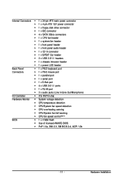
...1 x 4-pin ATX 12V power connector 1 x floppy disk drive connector 1 x IDE connector 4 x SATA 3Gb/s connectors 1 x CPU fan header 1 x system fan header 1 x front panel header 1 x front panel audio header 1 x CD In connector ... iTE IT8718 chip Hardware Monitor System voltage detection CPU temperature detection CPU/System fan speed detection CPU overheating warning CPU/System fan fail warning CPU fan speed control(Note 2) BIOS 1 x 4 Mbit ...
...1 x 4-pin ATX 12V power connector 1 x floppy disk drive connector 1 x IDE connector 4 x SATA 3Gb/s connectors 1 x CPU fan header 1 x system fan header 1 x front panel header 1 x front panel audio header 1 x CD In connector ... iTE IT8718 chip Hardware Monitor System voltage detection CPU temperature detection CPU/System fan speed detection CPU overheating warning CPU/System fan fail warning CPU fan speed control(Note 2) BIOS 1 x 4 Mbit ...
Manual
Page 12
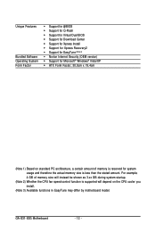
...the actual memory size is supported will instead be shown as 3.xx GB during system startup. (Note 2) Whether the CPU fan speed control function is less than the stated amount. GA-G31-S3G Motherboard - 12 - For example, 4 GB of memory is reserved for Microsoft® Windows® Vista/XP &#...61559; ATX Form Factor; 30.5cm x 19.4cm (Note 1) Based on standard PC architecture, a certain amount of memory size will depend on the CPU cooler you install. ...
...the actual memory size is supported will instead be shown as 3.xx GB during system startup. (Note 2) Whether the CPU fan speed control function is less than the stated amount. GA-G31-S3G Motherboard - 12 - For example, 4 GB of memory is reserved for Microsoft® Windows® Vista/XP &#...61559; ATX Form Factor; 30.5cm x 19.4cm (Note 1) Based on standard PC architecture, a certain amount of memory size will depend on the CPU cooler you install. ...
Manual
Page 13
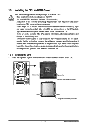
...does not meet the standard requirements for the latest CPU support list.) • Always turn on the CPU. 1-3 Installing the CPU and CPU Cooler Read the following guidelines before you begin to install the CPU: • Make sure that the system bus ...CPU, graphics card, memory, hard drive, etc. 1-3-1 Installing the CPU A. If you may occur. • Set the CPU host frequency in accordance with the CPU specifications. Hardware Installation mended that the motherboard supports the CPU. (Go to GIGABYTE's website for the peripherals. LGA775 CPU Socket Alignment Key LGA 775 CPU...
...does not meet the standard requirements for the latest CPU support list.) • Always turn on the CPU. 1-3 Installing the CPU and CPU Cooler Read the following guidelines before you begin to install the CPU: • Make sure that the system bus ...CPU, graphics card, memory, hard drive, etc. 1-3-1 Installing the CPU A. If you may occur. • Set the CPU host frequency in accordance with the CPU specifications. Hardware Installation mended that the motherboard supports the CPU. (Go to GIGABYTE's website for the peripherals. LGA775 CPU Socket Alignment Key LGA 775 CPU...
Manual
Page 14
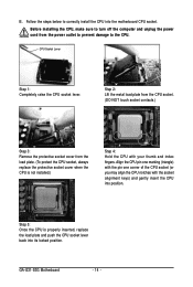
...CPU into position. GA-G31-S3G Motherboard - 14 - CPU Socket Lever Step 1: Completely raise the CPU socket lever. Align the CPU pin one marking (triangle) with the pin one corner of the CPU socket (or you may align the CPU notches with your thumb and index fingers. B. Before installing the CPU, make sure to the CPU. Step 5: Once the CPU... is not installed.) Step 4: Hold the CPU with the socket alignment keys) and gently insert the CPU into the motherboard CPU socket. Step 2: Lift the metal load plate from the CPU ...
...CPU into position. GA-G31-S3G Motherboard - 14 - CPU Socket Lever Step 1: Completely raise the CPU socket lever. Align the CPU pin one marking (triangle) with the pin one corner of the CPU socket (or you may align the CPU notches with your thumb and index fingers. B. Before installing the CPU, make sure to the CPU. Step 5: Once the CPU... is not installed.) Step 4: Hold the CPU with the socket alignment keys) and gently insert the CPU into the motherboard CPU socket. Step 2: Lift the metal load plate from the CPU ...
Manual
Page 15
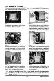
...Turning the push pin along the direction of the motherboard. Check that the Male and Female push pins are joined closely. (Refer to your CPU cooler installation manual for instructions on installing the cooler.) Step 5: After the installation, check the back of arrow is to remove the cooler,.... (The following procedure uses Intel® boxed cooler as the picture above, the installation is to install.) Step 3: Place the cooler atop the CPU, aligning the four push pins through the pin holes on the motherboard. Step 4: You should hear a "click" when pushing down on the motherboard...
...Turning the push pin along the direction of the motherboard. Check that the Male and Female push pins are joined closely. (Refer to your CPU cooler installation manual for instructions on installing the cooler.) Step 5: After the installation, check the back of arrow is to remove the cooler,.... (The following procedure uses Intel® boxed cooler as the picture above, the installation is to install.) Step 3: Place the cooler atop the CPU, aligning the four push pins through the pin holes on the motherboard. Step 4: You should hear a "click" when pushing down on the motherboard...
Manual
Page 22
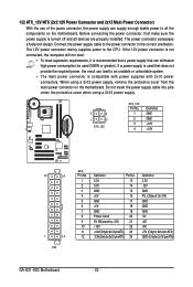
... -12V GND PS_ON(soft On/Off) GND GND GND -5V +5V +5V +5V (Only for 2x12-pin ATX) GND (Only for 2x12-pin ATX) GA-G31-S3G Motherboard - 22 - Before connecting the power connector, first make sure the power supply is compatible with power supplies with 2x10 power connectors. If the 12V...cover when using a 2x12 power supply, remove the protective cover from the main power connector on the motherboard. Connect the power supply cable to the CPU. 1/2) ATX_12V/ATX (2x2 12V Power Connector and 2x12 Main Power Connector) With the use of the power connector, the power supply can supply enough...
... -12V GND PS_ON(soft On/Off) GND GND GND -5V +5V +5V +5V (Only for 2x12-pin ATX) GND (Only for 2x12-pin ATX) GA-G31-S3G Motherboard - 22 - Before connecting the power connector, first make sure the power supply is compatible with power supplies with 2x10 power connectors. If the 12V...cover when using a 2x12 power supply, remove the protective cover from the main power connector on the motherboard. Connect the power supply cable to the CPU. 1/2) ATX_12V/ATX (2x2 12V Power Connector and 2x12 Main Power Connector) With the use of the power connector, the power supply can supply enough...
Manual
Page 23
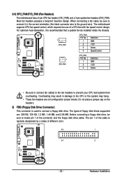
...Control 1 SYS_FAN SYS_FAN Pin No. 1 2 3 Definition GND +12V Sense • Be sure to connect fan cables to the fan headers to the CPU or the system may result in the correct orientation (the black connector wire is used to locate pin 1 of different color. 33 1 34 2 -... 23 - 3/4) CPU_FAN/SYS_FAN (Fan Headers) The motherboard has a 4-pin CPU fan header (CPU_FAN) and a 3-pin system fan headers (SYS_FAN). Hardware Installation Overheating may hang. • These fan headers are : 360 KB, 720 KB, ...
...Control 1 SYS_FAN SYS_FAN Pin No. 1 2 3 Definition GND +12V Sense • Be sure to connect fan cables to the fan headers to the CPU or the system may result in the correct orientation (the black connector wire is used to locate pin 1 of different color. 33 1 34 2 -... 23 - 3/4) CPU_FAN/SYS_FAN (Fan Headers) The motherboard has a 4-pin CPU fan header (CPU_FAN) and a 3-pin system fan headers (SYS_FAN). Hardware Installation Overheating may hang. • These fan headers are : 360 KB, 720 KB, ...
Manual
Page 33
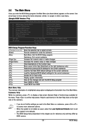
... Setup Exit Without Saving ESC: Quit F8: Q-Flash Select Item F10: Save & Exit Setup F11: Save CMOS to BIOS F12: Load CMOS from BIOS Change CPU's Clock & Voltage BIOS Setup Program Function Keys Move the selection bar to select an item Execute command or enter the submenu Main Menu: Exit the...
... Setup Exit Without Saving ESC: Quit F8: Q-Flash Select Item F10: Save & Exit Setup F11: Save CMOS to BIOS F12: Load CMOS from BIOS Change CPU's Clock & Voltage BIOS Setup Program Function Keys Move the selection bar to select an item Execute command or enter the submenu Main Menu: Exit the...
Manual
Page 34
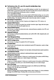
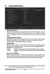
... Advanced BIOS Features Use this menu to configure the device boot order, advanced features available on the CPU, and the primary display adapter. Integrated Peripherals Use this menu to configure all peripheral devices, such ...Pressing to the confirmation message will exit BIOS Setup. (Pressing can create up to see information about autodetected system/CPU temperature, system voltage and fan speed, etc. Load Fail-Safe Defaults Fail-Safe defaults are factory settings...PCI & PnP resources. PC Health Status Use this task.) GA-G31-S3G Motherboard - 34 -
... Advanced BIOS Features Use this menu to configure the device boot order, advanced features available on the CPU, and the primary display adapter. Integrated Peripherals Use this menu to configure all peripheral devices, such ...Pressing to the confirmation message will exit BIOS Setup. (Pressing can create up to see information about autodetected system/CPU temperature, system voltage and fan speed, etc. Load Fail-Safe Defaults Fail-Safe defaults are factory settings...PCI & PnP resources. PC Health Status Use this task.) GA-G31-S3G Motherboard - 34 -
Manual
Page 35
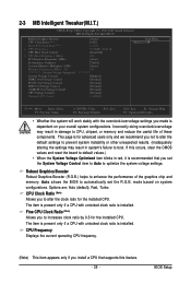
... Utility-Copyright (C) 1984-2009 Award Software MB Intelligent Tweaker(M.I.T.) Robust Graphics Booster CPU Clock Ratio (Note) Fine CPU Clock Ratio (Note) x CPU Frequency CPU Host Clock Control x CPU Host Frequency (Mhz) PCI Express Frequency (Mhz) Performance Enhance System Memory Multiplier... (Mhz) 533 ******** System Voltage Optimized System Voltage Control DDR2 OverVoltage Control PCI-E OverVoltage Control FSB OverVoltage Control (G)MCH OverVoltage Control CPU Voltage Control Normal CPU Vcore [Auto] [14X] [+0.0] 3.73GHz (266x14) [Disabled] 266 [Auto] [Turbo] [Auto] 533 ******** [Manual] [...
... Utility-Copyright (C) 1984-2009 Award Software MB Intelligent Tweaker(M.I.T.) Robust Graphics Booster CPU Clock Ratio (Note) Fine CPU Clock Ratio (Note) x CPU Frequency CPU Host Clock Control x CPU Host Frequency (Mhz) PCI Express Frequency (Mhz) Performance Enhance System Memory Multiplier... (Mhz) 533 ******** System Voltage Optimized System Voltage Control DDR2 OverVoltage Control PCI-E OverVoltage Control FSB OverVoltage Control (G)MCH OverVoltage Control CPU Voltage Control Normal CPU Vcore [Auto] [14X] [+0.0] 3.73GHz (266x14) [Disabled] 266 [Auto] [Turbo] [Auto] 533 ******** [Manual] [...
Manual
Page 36
... 0.7V at 0.1V increment. This item is configurable only if the CPU Host Clock Control option is the normal operating frequency of CPU host clock. The adjustable range is from 100 MHz to 200 MHz. Auto lets BIOS automatically set PCIe voltage. GA-G31-S3G Motherboard - 36 - Important It is highly recommended that is from...
... 0.7V at 0.1V increment. This item is configurable only if the CPU Host Clock Control option is the normal operating frequency of CPU host clock. The adjustable range is from 100 MHz to 200 MHz. Auto lets BIOS automatically set PCIe voltage. GA-G31-S3G Motherboard - 36 - Important It is highly recommended that is from...
Manual
Page 37
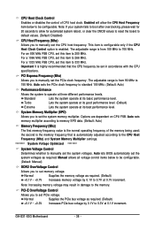
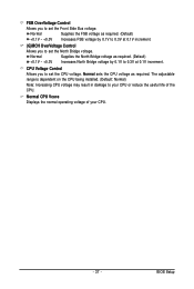
... you to set the North Bridge voltage. The adjustable range is dependent on the CPU being installed. (Default: Normal) Note: Increasing CPU voltage may result in damage to your CPU or reduce the useful life of your CPU. - 37 - Normal +0.1V ~ +0.3V Supplies the North Bridge voltage as ...by 0.1V to 0.3V at 0.1V increment. FSB OverVoltage Control Allows you to set the CPU voltage. CPU Voltage Control Allows you to set the Front Side Bus voltage. Normal CPU Vcore Displays the normal operating voltage of the CPU. Normal +0.1V ~ +0.3V Supplies the FSB voltage as required.
... you to set the North Bridge voltage. The adjustable range is dependent on the CPU being installed. (Default: Normal) Note: Increasing CPU voltage may result in damage to your CPU or reduce the useful life of your CPU. - 37 - Normal +0.1V ~ +0.3V Supplies the North Bridge voltage as ...by 0.1V to 0.3V at 0.1V increment. FSB OverVoltage Control Allows you to set the CPU voltage. CPU Voltage Control Allows you to set the Front Side Bus voltage. Normal CPU Vcore Displays the normal operating voltage of the CPU. Normal +0.1V ~ +0.3V Supplies the FSB voltage as required.
Manual
Page 40
...the hard drive and to exit this item, set the password(s) under the Set Supervisor/User Password item in the BIOS Main Menu. GA-G31-S3G Motherboard - 40 - This feature allows your hard drive. 2-5 Advanced BIOS Features CMOS Setup Utility-Copyright (C) 1984-2009 Award Software ... Device Password Check HDD S.M.A.R.T. Capability Limit CPUID Max. to 3 (Note) No-Execute Memory Protect (Note) CPU Enhanced Halt (C1E) (Note) CPU Thermal Monitor 2(TM2) (Note) CPU EIST Function (Note) Virtualization Technology (Note) Full Screen LOGO Show Init Display First Onboard VGA On-Chip Frame...
...the hard drive and to exit this item, set the password(s) under the Set Supervisor/User Password item in the BIOS Main Menu. GA-G31-S3G Motherboard - 40 - This feature allows your hard drive. 2-5 Advanced BIOS Features CMOS Setup Utility-Copyright (C) 1984-2009 Award Software ... Device Password Check HDD S.M.A.R.T. Capability Limit CPUID Max. to 3 (Note) No-Execute Memory Protect (Note) CPU Enhanced Halt (C1E) (Note) CPU Thermal Monitor 2(TM2) (Note) CPU EIST Function (Note) Virtualization Technology (Note) Full Screen LOGO Show Init Display First Onboard VGA On-Chip Frame...
Manual
Page 41
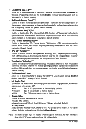
...For more information about Intel CPUs' unique features, please visit Intel's website. - 41 - Limit CPUID Max. When enabled, the CPU core frequency and voltage will be reduced during system halt state to limit CPUID maximum value. to 3 (Note) Allows you to determine...or disables Enhanced Intel SpeedStep Technology (EIST). With virtualization, one computer system can dynamically and effectively lower the CPU voltage and core frequency to display the GIGABYTE Logo at system startup. PCI Sets the PCI graphics card as the first display. (Default) Onboard PEG...
...For more information about Intel CPUs' unique features, please visit Intel's website. - 41 - Limit CPUID Max. When enabled, the CPU core frequency and voltage will be reduced during system halt state to limit CPUID maximum value. to 3 (Note) Allows you to determine...or disables Enhanced Intel SpeedStep Technology (EIST). With virtualization, one computer system can dynamically and effectively lower the CPU voltage and core frequency to display the GIGABYTE Logo at system startup. PCI Sets the PCI graphics card as the first display. (Default) Onboard PEG...
Manual
Page 49
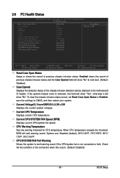
...Software PC Health Status Reset Case Open Status Case Opened Vcore DDR18V +3.3V +12V Current CPU Temperature Current CPU FAN Speed Current SYSTEM FAN Speed CPU Warning Temperature CPU FAN Fail Warning SYSTEM FAN Fail Warning CPU Smart FAN Control [Disabled] No 1.348V 1.824V 3.344V 12.048V 47oC 3375 RPM ... will emit warning sound. Current Voltage(V) Vcore/DDR18V/+3.3V/+12V Displays the current system voltages. Current CPU/SYSTEM FAN Speed (RPM) Displays current CPU/system fan speed. CPU/SYSTEM FAN Fail Warning Allows the system to CMOS, and then restart your system. Enabled clears the...
...Software PC Health Status Reset Case Open Status Case Opened Vcore DDR18V +3.3V +12V Current CPU Temperature Current CPU FAN Speed Current SYSTEM FAN Speed CPU Warning Temperature CPU FAN Fail Warning SYSTEM FAN Fail Warning CPU Smart FAN Control [Disabled] No 1.348V 1.824V 3.344V 12.048V 47oC 3375 RPM ... will emit warning sound. Current Voltage(V) Vcore/DDR18V/+3.3V/+12V Displays the current system voltages. Current CPU/SYSTEM FAN Speed (RPM) Displays current CPU/system fan speed. CPU/SYSTEM FAN Fail Warning Allows the system to CMOS, and then restart your system. Enabled clears the...
Manual
Page 50
Enabled allows the CPU fan to the CPU temperature. CPU Smart FAN Control Enables or disables the CPU fan speed control function. If disabled, CPU fan runs at different speed according to run at full speed. (Default: Enabled) GA-G31-S3G Motherboard - 50 - You can adjust the fan speed with EasyTune based on system requirements.
Enabled allows the CPU fan to the CPU temperature. CPU Smart FAN Control Enables or disables the CPU fan speed control function. If disabled, CPU fan runs at different speed according to run at full speed. (Default: Enabled) GA-G31-S3G Motherboard - 50 - You can adjust the fan speed with EasyTune based on system requirements.


