Manual
Page 27
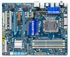
...The system reports system startup status by chassis. The front panel design may differ by issuing a beep code. Hard Drive Activity LED Reset Switch Power LED Chassis Intrusion Header • MSG/PWR (Message/Power/Sleep LED, Yellow/Purple): System Status LED Connects to the...). • SPEAK (Speaker, Orange): Connects to the pin assignments below. When connecting your system using the power switch (refer to Chapter 2, "BIOS Setup," "Power Management Setup," for information about beep codes. • HD (Hard Drive Activity LED, Blue) Connects to the power status indicator ...
...The system reports system startup status by chassis. The front panel design may differ by issuing a beep code. Hard Drive Activity LED Reset Switch Power LED Chassis Intrusion Header • MSG/PWR (Message/Power/Sleep LED, Yellow/Purple): System Status LED Connects to the...). • SPEAK (Speaker, Orange): Connects to the pin assignments below. When connecting your system using the power switch (refer to Chapter 2, "BIOS Setup," "Power Management Setup," for information about beep codes. • HD (Hard Drive Activity LED, Blue) Connects to the power status indicator ...
Manual
Page 31
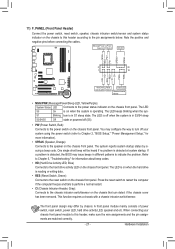
... values and before turning on the two pins to temporarily short the two pins or use a metal object like a screwdriver to Chapter 2, "BIOS Setup," for a few seconds. 18) COMA (Serial Port Header) The COMA header can provide one serial port via an optional COM port ...cable. date information and BIOS configurations) and reset the CMOS values to remove the jumper cap from the jumper. Definition 1 NDCD- 9 1 2 NSIN 10 2 3 NSOUT 4 NDTR- 5 GND 6 NDSR- 7 NRTS- 8 ...
... values and before turning on the two pins to temporarily short the two pins or use a metal object like a screwdriver to Chapter 2, "BIOS Setup," for a few seconds. 18) COMA (Serial Port Header) The COMA header can provide one serial port via an optional COM port ...cable. date information and BIOS configurations) and reset the CMOS values to remove the jumper cap from the jumper. Definition 1 NDCD- 9 1 2 NSIN 10 2 3 NSOUT 4 NDTR- 5 GND 6 NDSR- 7 NRTS- 8 ...
Manual
Page 33
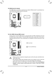
... latest version of the battery/ clearing CMOS jumper in the CMOS on using the current version of BIOS, it with caution. To upgrade the BIOS, use either the GIGABYTE Q-Flash or @BIOS utility. • Q-Flash allows the user to boot. Inadequately altering the settings may result in ...this occurs, try to clear the CMOS values and reset the board to default values. (Refer to clear the CMOS values.) - 33 - To access the BIOS ...
... latest version of the battery/ clearing CMOS jumper in the CMOS on using the current version of BIOS, it with caution. To upgrade the BIOS, use either the GIGABYTE Q-Flash or @BIOS utility. • Q-Flash allows the user to boot. Inadequately altering the settings may result in ...this occurs, try to clear the CMOS values and reset the board to default values. (Refer to clear the CMOS values.) - 33 - To access the BIOS ...
Manual
Page 37
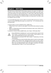
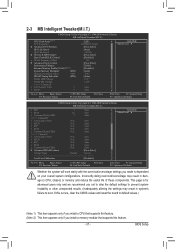
If this feature. - 37 - BIOS Setup Incorrectly doing overclock/overvoltage may result in damage to default values.) (Note 1) This item appears only if you install a CPU that supports this feature. (.../overvoltage settings you made is for advanced users only and we recommend you install a memory module that supports this occurs, clear the CMOS values and reset the board to CPU, chipset, or memory and reduce the useful life of these components.
If this feature. - 37 - BIOS Setup Incorrectly doing overclock/overvoltage may result in damage to default values.) (Note 1) This item appears only if you install a CPU that supports this feature. (.../overvoltage settings you made is for advanced users only and we recommend you install a memory module that supports this occurs, clear the CMOS values and reset the board to CPU, chipset, or memory and reduce the useful life of these components.

Manual
Page 41
... dynamically based on system components, when system instability occurs after overclocking, please wait for automated system reboot, or clear the CMOS values to reset the board to default values. (Default: Disabled) BCLK Frequency(Mhz) Allows you to adjust the amplitude of CPU base clock. As stability... clock prior to set in accordance with the CPU specifications. Racing Increases CPU frequency by 15% or 17% depending on CPU loading. BIOS Setup PCI Express Frequency(Mhz) Allows you to the North Bridge clock. CPU Clock Skew Allows you to set the PCIe clock frequency....
... dynamically based on system components, when system instability occurs after overclocking, please wait for automated system reboot, or clear the CMOS values to reset the board to default values. (Default: Disabled) BCLK Frequency(Mhz) Allows you to adjust the amplitude of CPU base clock. As stability... clock prior to set in accordance with the CPU specifications. Racing Increases CPU frequency by 15% or 17% depending on CPU loading. BIOS Setup PCI Express Frequency(Mhz) Allows you to the North Bridge clock. CPU Clock Skew Allows you to set the PCIe clock frequency....
Manual
Page 57
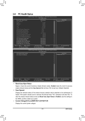
...(Default: Disabled) Case Opened Displays the detection status of previous chassis intrusion status. BIOS Setup 2-8 PC Health Status CMOS Setup Utility-Copyright (C) 1984-2009 Award Software PC Health Status Reset Case Open Status Case Opened Vcore DDR15V +3.3V +5V +12V Current System Temperature ...intrusion detection device attached to the CMOS, and then restart your system. To clear the chassis intrusion status record, set Reset Case Open Status to Enabled, save the settings to the motherboard CI header. Current Voltage(V) Vcore/DDR15V/+3.3V/+5V/+12V...
...(Default: Disabled) Case Opened Displays the detection status of previous chassis intrusion status. BIOS Setup 2-8 PC Health Status CMOS Setup Utility-Copyright (C) 1984-2009 Award Software PC Health Status Reset Case Open Status Case Opened Vcore DDR15V +3.3V +5V +12V Current System Temperature ...intrusion detection device attached to the CMOS, and then restart your system. To clear the chassis intrusion status record, set Reset Case Open Status to Enabled, save the settings to the motherboard CI header. Current Voltage(V) Vcore/DDR15V/+3.3V/+5V/+12V...
Manual
Page 71
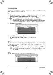
...)DfaotuandEnable Floppy A Loa d CMO S Default Enable HDD 1-0 Upda te BIOS from Drive and press . • The Save Main BIOS to Drive option allows you to save the BIOS file to Drive Enter : Run hi:Move Total size : 0 ESC:Reset Free size : 0 F10:Power Off 3. The monitor will display the ...update process. • Do not turn off or restart the system when the system is reading/updating the BIOS. • Do not remove the floppy disk, USB flash ...
...)DfaotuandEnable Floppy A Loa d CMO S Default Enable HDD 1-0 Upda te BIOS from Drive and press . • The Save Main BIOS to Drive option allows you to save the BIOS file to Drive Enter : Run hi:Move Total size : 0 ESC:Reset Free size : 0 F10:Power Off 3. The monitor will display the ...update process. • Do not turn off or restart the system when the system is reading/updating the BIOS. • Do not remove the floppy disk, USB flash ...
Manual
Page 76
...The total amount of time since activating Dynamic Energy Saver Advanced for the latest utility version) 17 CPU Power Saving Mode Switch (System will automatically reset when the total power saving reaches 99999999 Watts. Total Mode In Total Mode, users are set period of power saved will be recorded until re... close the application. (Note 1) Before using the DES function, make sure the CPU Enhanced Halt (C1E) and CPU EIST Function items in the BIOS Setup program are able to zero. (Note 5) Dynamic Energy Saver Meter will enter power saving mode after the system is restarted.
...The total amount of time since activating Dynamic Energy Saver Advanced for the latest utility version) 17 CPU Power Saving Mode Switch (System will automatically reset when the total power saving reaches 99999999 Watts. Total Mode In Total Mode, users are set period of power saved will be recorded until re... close the application. (Note 1) Before using the DES function, make sure the CPU Enhanced Halt (C1E) and CPU EIST Function items in the BIOS Setup program are able to zero. (Note 5) Dynamic Energy Saver Meter will enter power saving mode after the system is restarted.
Manual
Page 81
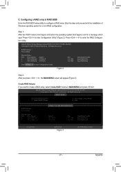
... Figure 3 [ENTER]-Select Menu - 81 - Create RAID Volume If you press + , the MAIN MENU screen will appear (Figure 3). Reset Disks to enter Configuration Utility.. Configuring a RAID array in RAID BIOS Enter the RAID BIOS setup utility to create a RAID array, select Create RAID Volume in MAIN MENU and press . Skip this step and...
... Figure 3 [ENTER]-Select Menu - 81 - Create RAID Volume If you press + , the MAIN MENU screen will appear (Figure 3). Reset Disks to enter Configuration Utility.. Configuring a RAID array in RAID BIOS Enter the RAID BIOS setup utility to create a RAID array, select Create RAID Volume in MAIN MENU and press . Skip this step and...
Manual
Page 83
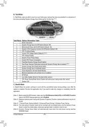
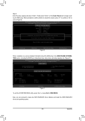
... Bootable Yes Type/Status(Vol ID) Non-RAID Disk Non-RAID Disk [hi]-Select [ESC]-Exit Figure 7 [ENTER]-Select Menu To exit the ICH10R RAID BIOS utility, press or select Exit in the DISK/VOLUME INFORMATION section, including the RAID level, stripe block size, array name, and array capacity, etc. (Figure... the array capacity and press . All Rights Reversed. [ MAIN MENU ] 1. Intel(R) Matrix Storage Manager option ROM v8.0.0.1039 ICH10R wRAID5 Copyright(C) 2003-08 Intel Corporation. Reset Disks to Non-RAID 4. Delete RAID Volume 3.
... Bootable Yes Type/Status(Vol ID) Non-RAID Disk Non-RAID Disk [hi]-Select [ESC]-Exit Figure 7 [ENTER]-Select Menu To exit the ICH10R RAID BIOS utility, press or select Exit in the DISK/VOLUME INFORMATION section, including the RAID level, stripe block size, array name, and array capacity, etc. (Figure... the array capacity and press . All Rights Reversed. [ MAIN MENU ] 1. Intel(R) Matrix Storage Manager option ROM v8.0.0.1039 ICH10R wRAID5 Copyright(C) 2003-08 Intel Corporation. Reset Disks to Non-RAID 4. Delete RAID Volume 3.


