
Manual
Page 5
... 5 Appendix...79 5-1 Configuring SATA Hard Drive(s 79 5-1-1 Configuring Intel ICH10R SATA Controllers 79 5-1-2 Configuring GIGABYTE SATA2 SATA Controller 85 5-1-2 Making a SATA RAID/AHCI Driver Diskette 91 5-1-4 Installing the SATA RAID/AHCI Driver and Operating System ...92 5-2 Configuring Audio Input and Output 102 5-2-1 Configuring 2/4/5.1/7.1-Channel Audio 102 5-2-2 Configuring S/PDIF In/Out 104 5-2-3 Configuring Microphone Recording 106 5-2-4 Using the Sound Recorder 108 ...
... 5 Appendix...79 5-1 Configuring SATA Hard Drive(s 79 5-1-1 Configuring Intel ICH10R SATA Controllers 79 5-1-2 Configuring GIGABYTE SATA2 SATA Controller 85 5-1-2 Making a SATA RAID/AHCI Driver Diskette 91 5-1-4 Installing the SATA RAID/AHCI Driver and Operating System ...92 5-2 Configuring Audio Input and Output 102 5-2-1 Configuring 2/4/5.1/7.1-Channel Audio 102 5-2-2 Configuring S/PDIF In/Out 104 5-2-3 Configuring Microphone Recording 106 5-2-4 Using the Sound Recorder 108 ...
Manual
Page 7
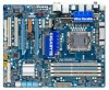
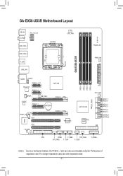
... R_SPDIF ATX_12V_2X USB_1394_1 USB_1394_2 R_USB USB_LAN LGA1366 CPU_FAN PHASE LED PWR_FAN GA-EX58-UD3R AUDIO F_AUDIO PCIEX1_1 (Note) RTL8111C PCIEX1_2 Intel® X58 SPDIF_I NB_FAN CODEC PCIEX4_1 BATTERY PCIEX16_1 IT8720 CD_IN SPDIF_O PCI1 PCI2 PCIEX16_2 TSB43AB23 DDR3_1 DDR3_3 DDR3_2 DDR3_4 Intel® ICH10R GIGABYTE SATA2 CLR_CMOS ATX SYS_FAN1 SATA2_1 SATA2_0 SATA2_3 SATA2_2 SATA2_5 SATA2_4 GSATA2_1...
... R_SPDIF ATX_12V_2X USB_1394_1 USB_1394_2 R_USB USB_LAN LGA1366 CPU_FAN PHASE LED PWR_FAN GA-EX58-UD3R AUDIO F_AUDIO PCIEX1_1 (Note) RTL8111C PCIEX1_2 Intel® X58 SPDIF_I NB_FAN CODEC PCIEX4_1 BATTERY PCIEX16_1 IT8720 CD_IN SPDIF_O PCI1 PCI2 PCIEX16_2 TSB43AB23 DDR3_1 DDR3_3 DDR3_2 DDR3_4 Intel® ICH10R GIGABYTE SATA2 CLR_CMOS ATX SYS_FAN1 SATA2_1 SATA2_0 SATA2_3 SATA2_2 SATA2_5 SATA2_4 GSATA2_1...
Manual
Page 10
...up to 1 floppy disk drive USB Integrated in the LGA1366 package (Go to GIGABYTE's website for the latest CPU support list.) L3 cache varies with CPU QPI Chipset Memory Audio 4.8GT/s, 6.4GT/s North Bridge: Intel® X58 Express Chipset...channel memory architecture Support for DDR3 2100/1333/1066/800 MHz memory modules (Go to GIGABYTE's website for the latest memory support list.) Realtek ALC888 codec High Definition Audio 2/4/5.1/7.1-channel Support for S/PDIF In/Out Support for SATA RAID ...
...up to 1 floppy disk drive USB Integrated in the LGA1366 package (Go to GIGABYTE's website for the latest CPU support list.) L3 cache varies with CPU QPI Chipset Memory Audio 4.8GT/s, 6.4GT/s North Bridge: Intel® X58 Express Chipset...channel memory architecture Support for DDR3 2100/1333/1066/800 MHz memory modules (Go to GIGABYTE's website for the latest memory support list.) Realtek ALC888 codec High Definition Audio 2/4/5.1/7.1-channel Support for S/PDIF In/Out Support for SATA RAID ...
Manual
Page 11
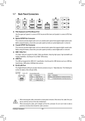
...3Gb/s connectors 1 x CPU fan header 3 x system fan headers 1 x power fan header 1 x North Bridge fan header 1 x front panel header 1 x front panel audio header 1 x CD In connector 1 x S/PDIF In header 1 x S/PDIF Out header 2 x USB 2.0/1.1 headers 1 x IEEE 1394a header 1 x serial port header ... coaxial S/PDIF Out connector 1 x optical S/PDIF Out connector 2 x IEEE 1394a ports 8 x USB 2.0/1.1 ports 1 x RJ-45 port 6 x audio jacks (Center/Subwoofer Speaker Out/Rear Speaker Out/ Side Speaker Out/Line In/Line Out/Microphone) iTE IT8720 chip Hardware Monitor w w w w w w...
...3Gb/s connectors 1 x CPU fan header 3 x system fan headers 1 x power fan header 1 x North Bridge fan header 1 x front panel header 1 x front panel audio header 1 x CD In connector 1 x S/PDIF In header 1 x S/PDIF Out header 2 x USB 2.0/1.1 headers 1 x IEEE 1394a header 1 x serial port header ... coaxial S/PDIF Out connector 1 x optical S/PDIF Out connector 2 x IEEE 1394a ports 8 x USB 2.0/1.1 ports 1 x RJ-45 port 6 x audio jacks (Center/Subwoofer Speaker Out/Rear Speaker Out/ Side Speaker Out/Line In/Line Out/Microphone) iTE IT8720 chip Hardware Monitor w w w w w w...
Manual
Page 20
... an IEEE 1394a device. USB Port The USB port supports the USB 2.0/1.1 specification. Use this feature, ensure that supports digital coaxial audio. RJ-45 LAN Port The Gigabit Ethernet LAN port provides Internet connection at up to connect a PS/2 keyboard. The following describes the ...USB flash drive and etc. Do not rock it straight out from the connector. Optical S/PDIF Out Connector This connector provides digital audio out to prevent an electrical short inside the cable connector. IEEE 1394a Port The IEEE 1394 port supports the IEEE 1394a specification, featuring...
... an IEEE 1394a device. USB Port The USB port supports the USB 2.0/1.1 specification. Use this feature, ensure that supports digital coaxial audio. RJ-45 LAN Port The Gigabit Ethernet LAN port provides Internet connection at up to connect a PS/2 keyboard. The following describes the ...USB flash drive and etc. Do not rock it straight out from the connector. Optical S/PDIF Out Connector This connector provides digital audio out to prevent an electrical short inside the cable connector. IEEE 1394a Port The IEEE 1394 port supports the IEEE 1394a specification, featuring...
Manual
Page 21
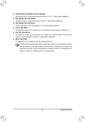
...The default Mic in jack. Only microphones still MUST be connected to the instructions on setting up a 2/4/5.1/7.1-channel audio con- Rear Speaker Out Jack (Black) Use this audio jack to the default Mic in jack ( ). Line Out Jack (Green) The default line out jack. ...walkman, etc. Refer to this jack. Side Speaker Out Jack (Gray) Use this audio jack to connect front speakers in a 4/5.1/7.1-channel audio configuration. Use this audio jack for line in Chapter 5, "Configuring 2/4/5.1/7.1-Channel Audio." - 21 - This jack can be used to connect side speakers in a 5.1/7.1-channel...
...The default Mic in jack. Only microphones still MUST be connected to the instructions on setting up a 2/4/5.1/7.1-channel audio con- Rear Speaker Out Jack (Black) Use this audio jack to the default Mic in jack ( ). Line Out Jack (Green) The default line out jack. ...walkman, etc. Refer to this jack. Side Speaker Out Jack (Gray) Use this audio jack to connect front speakers in a 4/5.1/7.1-channel audio configuration. Use this audio jack for line in Chapter 5, "Configuring 2/4/5.1/7.1-Channel Audio." - 21 - This jack can be used to connect side speakers in a 5.1/7.1-channel...
Manual
Page 28
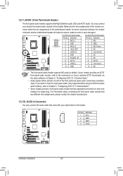
...You may connect your chassis provides an AC'97 front panel audio module, refer to the instructions on how to activate AC'97 functionality via the audio software in Chapter 5, "Configuring 2/4/5.1/7.1-Channel Audio." • Audio signals will make the device unable to work or even damage...motherboard header will be present on each wire instead of the front and back panel audio connections simultaneously. Definition 1 CD-L 2 GND 3 GND 4 CD-R Hardware Installation - 28 - If your chassis front panel audio module to the header. 1 Pin No. Make sure the wire assignments of the ...
...You may connect your chassis provides an AC'97 front panel audio module, refer to the instructions on how to activate AC'97 functionality via the audio software in Chapter 5, "Configuring 2/4/5.1/7.1-Channel Audio." • Audio signals will make the device unable to work or even damage...motherboard header will be present on each wire instead of the front and back panel audio connections simultaneously. Definition 1 CD-L 2 GND 3 GND 4 CD-R Hardware Installation - 28 - If your chassis front panel audio module to the header. 1 Pin No. Make sure the wire assignments of the ...
Manual
Page 29
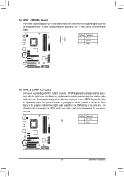
...expansion cards like graphics cards and sound cards. For information about connecting the S/PDIF digital audio cable, carefully read the manual for your motherboard to an audio device that supports digital audio out via an optional S/PDIF In cable. For purchasing the optional S/PDIF In cable,... 1 3 GND 15) SPDIF_O (S/PDIF Out Header) This header supports digital S/PDIF Out and connects a S/PDIF digital audio cable (provided by expansion cards) for digital audio output from your motherboard to your graphics card if you wish to connect an HDMI display to the graphics card and have...
...expansion cards like graphics cards and sound cards. For information about connecting the S/PDIF digital audio cable, carefully read the manual for your motherboard to an audio device that supports digital audio out via an optional S/PDIF In cable. For purchasing the optional S/PDIF In cable,... 1 3 GND 15) SPDIF_O (S/PDIF Out Header) This header supports digital S/PDIF Out and connects a S/PDIF digital audio cable (provided by expansion cards) for digital audio output from your motherboard to your graphics card if you wish to connect an HDMI display to the graphics card and have...
Manual
Page 36
... on the CPU, and the primary display adapter. Integrated Peripherals Use this menu to configure all peripheral devices, such as IDE, SATA, USB, integrated audio, and integrated LAN, etc. Power Management Setup Use this function to make changes in BIOS Setup. Set User Password Change, set , or disable...
... on the CPU, and the primary display adapter. Integrated Peripherals Use this menu to configure all peripheral devices, such as IDE, SATA, USB, integrated audio, and integrated LAN, etc. Power Management Setup Use this function to make changes in BIOS Setup. Set User Password Change, set , or disable...
Manual
Page 53
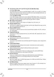
... will detect cabling issue and report the approximate distance to install a 3rd party add-in network card instead of wires will be used in audio card instead of the attached LAN cable. If no cable problem is detected on the LAN cable connected to a Gigabit hub or a 10...the following message will dynamically detect if a LAN cable is attached to the motherboard, the Status fields of all four pairs of using the onboard audio, set this item to Disabled. USB Mouse Function Allows USB mouse to be disabled automatically. (Default: Disabled) SMART LAN (LAN Cable Diagnostic Function)...
... will detect cabling issue and report the approximate distance to install a 3rd party add-in network card instead of wires will be used in audio card instead of the attached LAN cable. If no cable problem is detected on the LAN cable connected to a Gigabit hub or a 10...the following message will dynamically detect if a LAN cable is attached to the motherboard, the Status fields of all four pairs of using the onboard audio, set this item to Disabled. USB Mouse Function Allows USB mouse to be disabled automatically. (Default: Disabled) SMART LAN (LAN Cable Diagnostic Function)...
Manual
Page 102
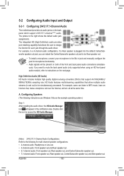
...: Refer to the following instructions use Windows Vista as the example operating system.) Step 1: After installing the audio driver, the HD Audio Manager icon will be simultaneously processed. High Definition Audio (HD Audio) HD Audio includes multiple high quality digital-to MP3 music, have an Internet chat, make a telephone call over the Internet, and etc...
...: Refer to the following instructions use Windows Vista as the example operating system.) Step 1: After installing the audio driver, the HD Audio Manager icon will be simultaneously processed. High Definition Audio (HD Audio) HD Audio includes multiple high quality digital-to MP3 music, have an Internet chat, make a telephone call over the Internet, and etc...
Manual
Page 103
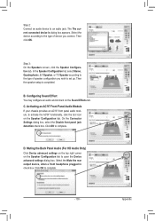
... plugged in check box. Step 3: On the Speakers screen, click the Speaker Configuration tab. Configuring Sound Effect You may configure an audio environment on the Sound Effects tab. On the Connector Settings dialog box, select the Disable front panel jack detection check box. Click OK... to the type of speaker configuration you connect. Appendix Step 2: Connect an audio device to set up. In the Speaker Configuration list, select Stereo, Quadraphonic, 5.1 Speaker, or 7.1 Speaker according to the type of device...
... plugged in check box. Step 3: On the Speakers screen, click the Speaker Configuration tab. Configuring Sound Effect You may configure an audio environment on the Sound Effects tab. On the Connector Settings dialog box, select the Disable front panel jack detection check box. Click OK... to the type of speaker configuration you connect. Appendix Step 2: Connect an audio device to set up. In the Speaker Configuration list, select Stereo, Quadraphonic, 5.1 Speaker, or 7.1 Speaker according to the type of device...
Manual
Page 104
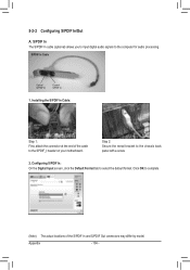
.../Out A. Step 2: Secure the metal bracket to select the default format. Click OK to the computer for audio processing. Appendix - 104 - S/PDIF In The S/PDIF In cable (optional) allows you to input digital audio signals to complete. (Note) The actual locations of the cable to the SPDIF_I header on your motherboard. Installing...
.../Out A. Step 2: Secure the metal bracket to select the default format. Click OK to the computer for audio processing. Appendix - 104 - S/PDIF In The S/PDIF In cable (optional) allows you to input digital audio signals to complete. (Note) The actual locations of the cable to the SPDIF_I header on your motherboard. Installing...
Manual
Page 105
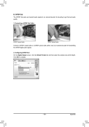
Click OK to an external decoder for decoding to get the best audio quality. 1. Connecting a S/PDIF Out Cable: S/PDIF Coaxial Cable S/PDIF Optical Cable Connect a S/PDIF coaxial cable or a S/PDIF optical cable (either one) to complete. - 105 - Appendix S/PDIF Out The S/PDIF Out jacks can transmit audio signals to an external decoder for transmitting the S/PDIF digital audio signals. 2. B. Configuring S/PDIF Out: On the Digital Output screen, click the Default Format tab and then select the sample rate and bit depth.
Click OK to an external decoder for decoding to get the best audio quality. 1. Connecting a S/PDIF Out Cable: S/PDIF Coaxial Cable S/PDIF Optical Cable Connect a S/PDIF coaxial cable or a S/PDIF optical cable (either one) to complete. - 105 - Appendix S/PDIF Out The S/PDIF Out jacks can transmit audio signals to an external decoder for transmitting the S/PDIF digital audio signals. 2. B. Configuring S/PDIF Out: On the Digital Output screen, click the Default Format tab and then select the sample rate and bit depth.
Manual
Page 106
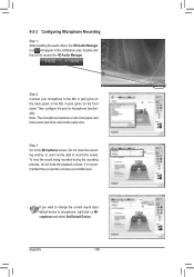
... you set the volumes at the same time. Step 2: Connect your microphone to record the sound. 5-2-3 Configuring Microphone Recording Step 1: After installing the audio driver, the HD Audio Manager icon will appear in jack (pink) on the front panel. Note: The microphone functions on Microphone and select Set Default Device. Step 3: Go...
... you set the volumes at the same time. Step 2: Connect your microphone to record the sound. 5-2-3 Configuring Microphone Recording Step 1: After installing the audio driver, the HD Audio Manager icon will appear in jack (pink) on the front panel. Note: The microphone functions on Microphone and select Set Default Device. Step 3: Go...
Manual
Page 107
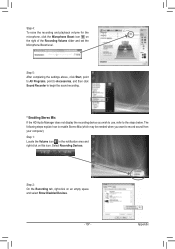
..., click Start, point to All Programs, point to Accessories, and then click Sound Recorder to begin the sound recording. * Enabling Stereo Mix If the HD Audio Manager does not display the recording device you want to the steps below. Select Recording Devices. Step 1: Locate the Volume icon in the notification area...
..., click Start, point to All Programs, point to Accessories, and then click Sound Recorder to begin the sound recording. * Enabling Stereo Mix If the HD Audio Manager does not display the recording device you want to the steps below. Select Recording Devices. Step 1: Locate the Volume icon in the notification area...
Manual
Page 108
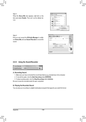
... in a digital media player program that supports your audio file format. To record the audio, click the Start Recording button . 3. Be sure to the computer. 2. Playing the Recorded Sound You can access the HD Audio Manager to configure Stereo Mix and use Sound Recorder ...to record the sound. 5-2-4 Using the Sound Recorder A. microphone) to save the recorded audio file upon completion. B. To stop recording audio, click the Stop Recording button . Step 4: Now you have connected the sound input device (e.g. Then set it as the...
... in a digital media player program that supports your audio file format. To record the audio, click the Start Recording button . 3. Be sure to the computer. 2. Playing the Recorded Sound You can access the HD Audio Manager to configure Stereo Mix and use Sound Recorder ...to record the sound. 5-2-4 Using the Sound Recorder A. microphone) to save the recorded audio file upon completion. B. To stop recording audio, click the Stop Recording button . Step 4: Now you have connected the sound input device (e.g. Then set it as the...
Manual
Page 109
...If yes, please disable this device. (If not, skip this step.) Step 3: Then go back to the Support&Downloads\Motherboards\FAQ page on GIGABYTE's website. 5-3 Troubleshooting 5-3-1 Frequently Asked Questions To read more details, go to show the advanced options. If not, please update it from ...Microsoft's website. For more FAQs for High Definition Audio and select Disable and Uninstall. If your motherboard, please go to My Computer > Properties > Hardware > Device Manager > System devices and...
...If yes, please disable this device. (If not, skip this step.) Step 3: Then go back to the Support&Downloads\Motherboards\FAQ page on GIGABYTE's website. 5-3 Troubleshooting 5-3-1 Frequently Asked Questions To read more details, go to show the advanced options. If not, please update it from ...Microsoft's website. For more FAQs for High Definition Audio and select Disable and Uninstall. If your motherboard, please go to My Computer > Properties > Hardware > Device Manager > System devices and...


