Manual
Page 3
..., read the User's Manual. Check your motherboard looks like this product, GIGABYTE provides the following types of documentations: For quick set-up of GIGABYTE. Disclaimer Information in any form or by GIGABYTE without GIGABYTE's prior written permission. For instructions on how to use of this manual ...in this manual is protected by copyright laws and is 1.0. For product-related information, check on our website at: http://www.gigabyte.com.tw Identifying Your Motherboard Revision The revision number on our website. No part of this : "REV: X.X." All rights reserved...
..., read the User's Manual. Check your motherboard looks like this product, GIGABYTE provides the following types of documentations: For quick set-up of GIGABYTE. Disclaimer Information in any form or by GIGABYTE without GIGABYTE's prior written permission. For instructions on how to use of this manual ...in this manual is protected by copyright laws and is 1.0. For product-related information, check on our website at: http://www.gigabyte.com.tw Identifying Your Motherboard Revision The revision number on our website. No part of this : "REV: X.X." All rights reserved...
Manual
Page 4
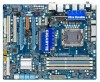
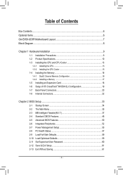
Table of Contents Box Contents...6 Optional Items...6 GA-EX58-UD3R Motherboard Layout 7 Block Diagram...8 Chapter 1 Hardware Installation 9 1-1 Installation Precautions 9 1-2 Product Specifications 10 1-3 Installing the CPU and CPU Cooler 13 1-3-1 Installing the CPU 13 1-3-2 Installing the ... BIOS Features 50 2-6 Integrated Peripherals 52 2-7 Power Management Setup 55 2-8 PC Health Status 57 2-9 Load Fail-Safe Defaults 59 2-10 Load Optimized Defaults 59 2-11 Set Supervisor/User Password 60 2-12 Save & Exit Setup 61 2-13 Exit Without Saving 61 - 4 -
Table of Contents Box Contents...6 Optional Items...6 GA-EX58-UD3R Motherboard Layout 7 Block Diagram...8 Chapter 1 Hardware Installation 9 1-1 Installation Precautions 9 1-2 Product Specifications 10 1-3 Installing the CPU and CPU Cooler 13 1-3-1 Installing the CPU 13 1-3-2 Installing the ... BIOS Features 50 2-6 Integrated Peripherals 52 2-7 Power Management Setup 55 2-8 PC Health Status 57 2-9 Load Fail-Safe Defaults 59 2-10 Load Optimized Defaults 59 2-11 Set Supervisor/User Password 60 2-12 Save & Exit Setup 61 2-13 Exit Without Saving 61 - 4 -
Manual
Page 9
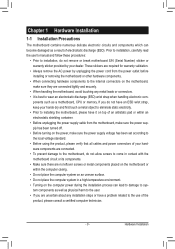
... the motherboard, make sure the power supply has been turned off. • Before turning on the power, make sure the power supply voltage has been set according to the local voltage standard. • Before using the product, please verify that all cables and power connectors of your hands dry and first...
... the motherboard, make sure the power supply has been turned off. • Before turning on the power, make sure the power supply voltage has been set according to the local voltage standard. • Before using the product, please verify that all cables and power connectors of your hands dry and first...

Manual
Page 13
...before installing the CPU to prevent hardware damage. • Locate the pin one of the CPU. Hardware Installation If you wish to GIGABYTE's website for the peripherals. LGA1366 CPU Socket Pin One Corner of the CPU Socket Alignment Key Alignment Key LGA1366 CPU Triangle Pin ...be inserted if oriented incorrectly. (Or you begin to install the CPU: • Make sure that the motherboard supports the CPU. (Go to set beyond the standard specifications, please do so according to your hardware specifications including the CPU, graphics card, memory, hard drive, etc. 1-3-1 Installing the...
...before installing the CPU to prevent hardware damage. • Locate the pin one of the CPU. Hardware Installation If you wish to GIGABYTE's website for the peripherals. LGA1366 CPU Socket Pin One Corner of the CPU Socket Alignment Key Alignment Key LGA1366 CPU Triangle Pin ...be inserted if oriented incorrectly. (Or you begin to install the CPU: • Make sure that the motherboard supports the CPU. (Go to set beyond the standard specifications, please do so according to your hardware specifications including the CPU, graphics card, memory, hard drive, etc. 1-3-1 Installing the...
Manual
Page 19
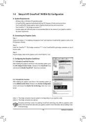
.... System Requirements - Two CrossFire (Note 1)/SLI bridge connectors (Note 2) - Step 2: Insert the CrossFire (Note 1)/SLI bridge connectors (Note 2) in the operating system, go to the Set SLI Configuration screen and ensure the Enable SLI technology check box is selected. Step 3: Plug the display cable into the graphics card on the PCI...
.... System Requirements - Two CrossFire (Note 1)/SLI bridge connectors (Note 2) - Step 2: Insert the CrossFire (Note 1)/SLI bridge connectors (Note 2) in the operating system, go to the Set SLI Configuration screen and ensure the Enable SLI technology check box is selected. Step 3: Plug the display cable into the graphics card on the PCI...
Manual
Page 21
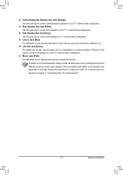
... - Line Out Jack (Green) The default line out jack. Use this audio jack to the default Mic in jack ( ). In addition to the default speakers settings, the ~ audio jacks can be reconfigured to connect front speakers in a 4/5.1/7.1-channel audio configuration. Center/Subwoofer Speaker Out Jack (Orange) Use this audio jack for... can be used to perform different functions via the audio software. Only microphones still MUST be connected to this audio jack to the instructions on setting up a 2/4/5.1/7.1-channel audio con-
... - Line Out Jack (Green) The default line out jack. Use this audio jack to the default Mic in jack ( ). In addition to the default speakers settings, the ~ audio jacks can be reconfigured to connect front speakers in a 4/5.1/7.1-channel audio configuration. Center/Subwoofer Speaker Out Jack (Orange) Use this audio jack for... can be used to perform different functions via the audio software. Only microphones still MUST be connected to this audio jack to the instructions on setting up a 2/4/5.1/7.1-channel audio con-
Manual
Page 25
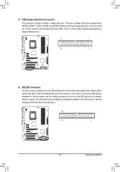
... devices such as hard drives and optical drives. The types of the IDE devices (for example, master or slave). (For information about configuring master/slave settings for the IDE devices, read the instructions from the device manufacturers.) 39 1 40 2 - 25 - Before attaching the IDE cable, locate the foolproof groove on the...
... devices such as hard drives and optical drives. The types of the IDE devices (for example, master or slave). (For information about configuring master/slave settings for the IDE devices, read the instructions from the device manufacturers.) 39 1 40 2 - 25 - Before attaching the IDE cable, locate the foolproof groove on the...
Manual
Page 31
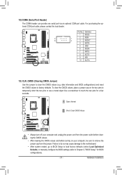
... damage to the motherboard. • After system restart, go to BIOS Setup to load factory defaults (select Load Optimized Defaults) or manually configure the BIOS settings (refer to clear the CMOS values (e.g. Hardware Installation For purchasing the optional COM port cable, please contact the local dealer. Pin No. 18) COMA (Serial...
... damage to the motherboard. • After system restart, go to BIOS Setup to load factory defaults (select Load Optimized Defaults) or manually configure the BIOS settings (refer to clear the CMOS values (e.g. Hardware Installation For purchasing the optional COM port cable, please contact the local dealer. Pin No. 18) COMA (Serial...
Manual
Page 33
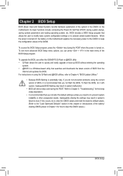
...system instability or other unexpected results. Refer to Chapter 5, "Troubleshooting," for how to clear the CMOS values.) - 33 - Inadequately altering the settings may result in the CMOS. BIOS Setup To flash the BIOS, do not encounter problems using the Q-Flash and @BIOS utilities, refer to activate..." section in this chapter or introductions of the battery/ clearing CMOS jumper in the CMOS on . To upgrade the BIOS, use either the GIGABYTE Q-Flash or @BIOS utility. • Q-Flash allows the user to quickly and easily upgrade or back up BIOS without entering the operating system...
...system instability or other unexpected results. Refer to Chapter 5, "Troubleshooting," for how to clear the CMOS values.) - 33 - Inadequately altering the settings may result in the CMOS. BIOS Setup To flash the BIOS, do not encounter problems using the Q-Flash and @BIOS utilities, refer to activate..." section in this chapter or introductions of the battery/ clearing CMOS jumper in the CMOS on . To upgrade the BIOS, use either the GIGABYTE Q-Flash or @BIOS utility. • Q-Flash allows the user to quickly and easily upgrade or back up BIOS without entering the operating system...
Manual
Page 34
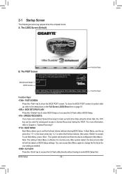
... Boot Menu, use the up hard drive data using the driver disk, the key can access Boot Menu again to change the first boot device setting as needed. : Q-FLASH Press the key to access the Q-Flash utility directly without entering BIOS Setup. BIOS Setup - 34 - 2-1 Startup ... BIOS Setup or to access the Q-Flash utility in BIOS Setup. : XPRESS RECOVERY2 If you to Xpress Recovery2 during the POST. Motherboard Model BIOS Version EX58-UD3R E3 . . . . : BIOS Setup : XpressRecovery2 : Boot Menu : Qflash 04/13/2009-X58-ICH10-7A89QG0EC-00 Function Keys Function Keys Function Keys: : POST...
... Boot Menu, use the up hard drive data using the driver disk, the key can access Boot Menu again to change the first boot device setting as needed. : Q-FLASH Press the key to access the Q-Flash utility directly without entering BIOS Setup. BIOS Setup - 34 - 2-1 Startup ... BIOS Setup or to access the Q-Flash utility in BIOS Setup. : XPRESS RECOVERY2 If you to Xpress Recovery2 during the POST. Motherboard Model BIOS Version EX58-UD3R E3 . . . . : BIOS Setup : XpressRecovery2 : Boot Menu : Qflash 04/13/2009-X58-ICH10-7A89QG0EC-00 Function Keys Function Keys Function Keys: : POST...
Manual
Page 35
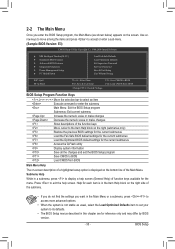
... Help block on the right (submenus only) Restore the previous BIOS settings for the current submenus Load the Fail-Safe BIOS default settings for the current submenus Load the Optimized BIOS default settings for the menu. Help for each item is in the Item Help...61565; Advanced BIOS Features Integrated Peripherals Power Management Setup PC Health Status Load Fail-Safe Defaults Load Optimized Defaults Set Supervisor Password Set User Password Save & Exit Setup Exit Without Saving ESC: Quit F8: Q-Flash Select Item F10: Save & Exit Setup Change CPU's ...
... Help block on the right (submenus only) Restore the previous BIOS settings for the current submenus Load the Fail-Safe BIOS default settings for the current submenus Load the Optimized BIOS default settings for the menu. Help for each item is in the Item Help...61565; Advanced BIOS Features Integrated Peripherals Power Management Setup PC Health Status Load Fail-Safe Defaults Load Optimized Defaults Set Supervisor Password Set User Password Save & Exit Setup Exit Without Saving ESC: Quit F8: Q-Flash Select Item F10: Save & Exit Setup Change CPU's ...
Manual
Page 36
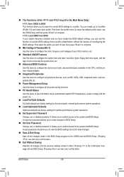
... allows you to restrict access to make changes. Save & Exit Setup Save all the changes made in BIOS Setup. Set User Password Change, set , or disable password. It allows you to the system and BIOS Setup. First select the profile you wish to load, then press to...this menu to configure the clock, frequency and voltages of your system becomes unstable and you have loaded the BIOS default settings, you to save the current BIOS settings to see information about autodetected system/CPU temperature, system voltage and fan speed, etc. Load Fail-Safe Defaults...
... allows you to restrict access to make changes. Save & Exit Setup Save all the changes made in BIOS Setup. Set User Password Change, set , or disable password. It allows you to the system and BIOS Setup. First select the profile you wish to load, then press to...this menu to configure the clock, frequency and voltages of your system becomes unstable and you have loaded the BIOS default settings, you to save the current BIOS settings to see information about autodetected system/CPU temperature, system voltage and fan speed, etc. Load Fail-Safe Defaults...
Manual
Page 37
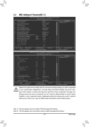
... a CPU that supports this feature. (Note 2) This item appears only if you not to alter the default settings to prevent system instability or other unexpected results. (Inadequately altering the settings may result in system's failure to CPU, chipset, or memory and reduce the useful life of these components....: Fail-Safe Defaults ESC: Exit F1: General Help F7: Optimized Defaults Whether the system will work stably with the overclock/overvoltage settings you made is for advanced users only and we recommend you install a memory module that supports this feature. - 37 - BIOS Setup
... a CPU that supports this feature. (Note 2) This item appears only if you not to alter the default settings to prevent system instability or other unexpected results. (Inadequately altering the settings may result in system's failure to CPU, chipset, or memory and reduce the useful life of these components....: Fail-Safe Defaults ESC: Exit F1: General Help F7: Optimized Defaults Whether the system will work stably with the overclock/overvoltage settings you made is for advanced users only and we recommend you install a memory module that supports this feature. - 37 - BIOS Setup

Manual
Page 40
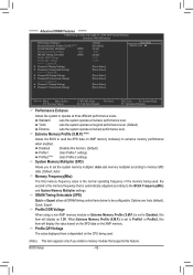
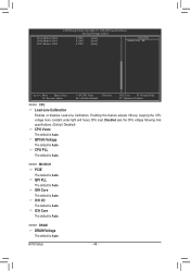
UnCore Frequency Allows you to set the QPI Link speed. Options are : Auto (default), x36, Slow Mode. Options are : Auto (default), x12~x16. ******** UnCore & QPI Features ******** CMOS Setup Utility-Copyright (C) 1984-...: Previous Values +/-/PU/PD: Value F10: Save F6: Fail-Safe Defaults ESC: Exit F1: General Help F7: Optimized Defaults QPI Link Speed Allows you to set the UnCore frequency. Isochronous Support Determines whether to enable specific streams between the IOH and ICH. (Default: Enabled) ******** Advanced Clock Control ******** CMOS Setup Utility-Copyright...
UnCore Frequency Allows you to set the QPI Link speed. Options are : Auto (default), x36, Slow Mode. Options are : Auto (default), x12~x16. ******** UnCore & QPI Features ******** CMOS Setup Utility-Copyright (C) 1984-...: Previous Values +/-/PU/PD: Value F10: Save F6: Fail-Safe Defaults ESC: Exit F1: General Help F7: Optimized Defaults QPI Link Speed Allows you to set the UnCore frequency. Isochronous Support Determines whether to enable specific streams between the IOH and ICH. (Default: Enabled) ******** Advanced Clock Control ******** CMOS Setup Utility-Copyright...

Manual
Page 41
...capability of your system fails to boot after overclocking, lower the overclocking ratio. >>>>> Advanced Clock Control CPU Clock Drive Allows you to manually set the CPU clock prior to maximize system performance. Options are : 700mV, 800mV (default), 900mV, 1000mV. BIOS Setup Note: If your ... only if the Base Clock(BCLK) Control option is from 100 MHz to adjust the amplitude of the CPU and North Bridge clock. Auto sets the PCIe clock frequency to standard 100 MHz. (Default: Auto) C.I.A.2 CPU Intelligent Accelerator 2 (C.I .A.2 allows your system hardware components. Note...
...capability of your system fails to boot after overclocking, lower the overclocking ratio. >>>>> Advanced Clock Control CPU Clock Drive Allows you to manually set the CPU clock prior to maximize system performance. Options are : 700mV, 800mV (default), 900mV, 1000mV. BIOS Setup Note: If your ... only if the Base Clock(BCLK) Control option is from 100 MHz to adjust the amplitude of the CPU and North Bridge clock. Auto sets the PCIe clock frequency to standard 100 MHz. (Default: Auto) C.I.A.2 CPU Intelligent Accelerator 2 (C.I .A.2 allows your system hardware components. Note...
Manual
Page 42
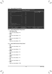
... different performance levels. System Memory Multiplier (SPD) Allows you install a memory module that is set to Profile1 or Profile2, this item will display the value based on the SPD data on the... Timing Selectable (SPD) Profile DDR Voltage Profile QPI Voltage >>>>> Channel A } Channel A Timing Settings } Channel A Turnaround Settings >>>>> Channel B } Channel B Timing Settings } Channel B Turnaround Settings >>>>> Channel C } Channel C Timing Settings } Channel C Turnaround Settings [Turbo] [Disabled] [Auto] 1066 [Auto] 1.5V 1.15V [Press Enter] [Press Enter...
... different performance levels. System Memory Multiplier (SPD) Allows you install a memory module that is set to Profile1 or Profile2, this item will display the value based on the SPD data on the... Timing Selectable (SPD) Profile DDR Voltage Profile QPI Voltage >>>>> Channel A } Channel A Timing Settings } Channel A Turnaround Settings >>>>> Channel B } Channel B Timing Settings } Channel B Turnaround Settings >>>>> Channel C } Channel C Timing Settings } Channel C Turnaround Settings [Turbo] [Disabled] [Auto] 1066 [Auto] 1.5V 1.15V [Press Enter] [Press Enter...
Manual
Page 43
.... - 43 - tRFC Options are : Auto (default), 1~31. tWL Options are : Auto (default), 1~31. tWTR Options are : Auto (default), 1~8. >>>>> Channel A/B/C Timing Settings CMOS Setup Utility-Copyright (C) 1984-2009 Award Software Channel A Timing Settings >>>>> Channel A Standard Timing Control x CAS Latency Time 7 x tRCD 7 x tRP 7 x tRAS 20 >>>>> Channel A Advanced Timing Control x tRC 27 x tRRD 4 x tWTR 4 x tWR...
.... - 43 - tRFC Options are : Auto (default), 1~31. tWL Options are : Auto (default), 1~31. tWTR Options are : Auto (default), 1~8. >>>>> Channel A/B/C Timing Settings CMOS Setup Utility-Copyright (C) 1984-2009 Award Software Channel A Timing Settings >>>>> Channel A Standard Timing Control x CAS Latency Time 7 x tRCD 7 x tRP 7 x tRAS 20 >>>>> Channel A Advanced Timing Control x tRC 27 x tRRD 4 x tWTR 4 x tWR...
Manual
Page 44
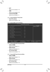
Command Rate(CMD) Options are: Auto (default), 1~3. >>>>> Channel A/B/C Misc Timing Control Round Trip Latency Options are: Auto (default), 1~255. >>>>> Channel A/B/C Turnaround Settings CMOS Setup Utility-Copyright (C) 1984-2009 Award Software Channel A Turnaround Settings >>>>> Channel A Writes Followed by Reads x Different DIMMs 7 x Different Ranks 7 x On The Same Rank 6 >>>>> Channel A Reads Followed by Writes x Different DIMMs...
Command Rate(CMD) Options are: Auto (default), 1~3. >>>>> Channel A/B/C Misc Timing Control Round Trip Latency Options are: Auto (default), 1~255. >>>>> Channel A/B/C Turnaround Settings CMOS Setup Utility-Copyright (C) 1984-2009 Award Software Channel A Turnaround Settings >>>>> Channel A Writes Followed by Reads x Different DIMMs 7 x Different Ranks 7 x On The Same Rank 6 >>>>> Channel A Reads Followed by Writes x Different DIMMs...
Manual
Page 46
... Voltage The default is Auto. CMOS Setup Utility-Copyright (C) 1984-2009 Award Software Advanced Voltage Control Ch-A Address VRef. ICH I/O The default is Auto. Disabled sets the CPU voltage following Intel specifications. (Default: Disabled) CPU Vcore The default is Auto. Ch-C Address VRef. 0.750V 0.750V 0.750V [Auto] [Auto] [Auto] Item Help...
... Voltage The default is Auto. CMOS Setup Utility-Copyright (C) 1984-2009 Award Software Advanced Voltage Control Ch-A Address VRef. ICH I/O The default is Auto. Disabled sets the CPU voltage following Intel specifications. (Default: Disabled) CPU Vcore The default is Auto. Ch-C Address VRef. 0.750V 0.750V 0.750V [Auto] [Auto] [Auto] Item Help...
Manual
Page 48
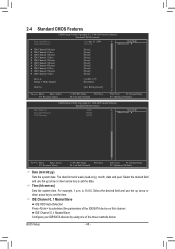
Select the desired field and use the up arrow or down arrow key to set the time. The date format is 13:0:0. Time (hh:mm:ss) Sets the system time. IDE Channel 0, 1 Master/Slave IDE HDD Auto-Detection Press to set the date. For example, 1 p.m. Select the desired field and use the up arrow...: Select F5: Previous Values +/-/PU/PD: Value F10: Save F6: Fail-Safe Defaults ESC: Exit F1: General Help F7: Optimized Defaults Date (mm:dd:yy) Sets the system date.
Select the desired field and use the up arrow or down arrow key to set the time. The date format is 13:0:0. Time (hh:mm:ss) Sets the system time. IDE Channel 0, 1 Master/Slave IDE HDD Auto-Detection Press to set the date. For example, 1 p.m. Select the desired field and use the up arrow...: Select F5: Previous Values +/-/PU/PD: Value F10: Save F6: Fail-Safe Defaults ESC: Exit F1: General Help F7: Optimized Defaults Date (mm:dd:yy) Sets the system date.


