Manual
Page 1
GA-EP45T-UD3LR LGA775 socket motherboard for Intel® Core TM processor family/ Intel® Pentium® processor family/Intel® Celeron® processor family User's Manual Rev. 1101 12ME-EP45TU3LR-1101R
GA-EP45T-UD3LR LGA775 socket motherboard for Intel® Core TM processor family/ Intel® Pentium® processor family/Intel® Celeron® processor family User's Manual Rev. 1101 12ME-EP45TU3LR-1101R
Manual
Page 2
Motherboard GA-EP45T-UD3LR Oct. 24, 2008 Motherboard GA-EP45T-UD3LR Oct. 24, 2008
Motherboard GA-EP45T-UD3LR Oct. 24, 2008 Motherboard GA-EP45T-UD3LR Oct. 24, 2008
Manual
Page 3
... property of this : "REV: X.X." Documentation Classifications In order to their respective owners. For product-related information, check on our website at: http://www.gigabyte.com.tw Identifying Your Motherboard Revision The revision number on our website. Example: All rights reserved. Disclaimer Information in this manual are legally registered to assist in this...
... property of this : "REV: X.X." Documentation Classifications In order to their respective owners. For product-related information, check on our website at: http://www.gigabyte.com.tw Identifying Your Motherboard Revision The revision number on our website. Example: All rights reserved. Disclaimer Information in this manual are legally registered to assist in this...
Manual
Page 4
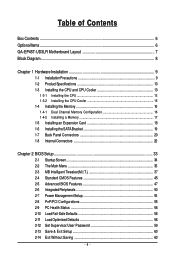
Table of Contents Box Contents ...6 OptionalItems...6 GA-EP45T-UD3LR Motherboard Layout 7 Block Diagram...8 Chapter 1 Hardware Installation 9 1-1 Installation Precautions 9 1-2 Product Specifications 10 1-3 Installing the CPU and CPU Cooler 13 1-3-1 Installing the CPU 13 1-3-2 Installing the CPU ...
Table of Contents Box Contents ...6 OptionalItems...6 GA-EP45T-UD3LR Motherboard Layout 7 Block Diagram...8 Chapter 1 Hardware Installation 9 1-1 Installation Precautions 9 1-2 Product Specifications 10 1-3 Installing the CPU and CPU Cooler 13 1-3-1 Installing the CPU 13 1-3-2 Installing the CPU ...
Manual
Page 6
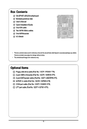
Box Contents GA-EP45T-UD3LR motherboard Motherboard driver disk User's Manual Quick Installation Guide One IDE cable Two SATA 3Gb/s cables One SATA bracket I/O Shield • The box contents above are subject to change without notice. • The motherboard image is for reference only and the actual items shall depend on product package you obtain. Optional Items...
Box Contents GA-EP45T-UD3LR motherboard Motherboard driver disk User's Manual Quick Installation Guide One IDE cable Two SATA 3Gb/s cables One SATA bracket I/O Shield • The box contents above are subject to change without notice. • The motherboard image is for reference only and the actual items shall depend on product package you obtain. Optional Items...

Manual
Page 7
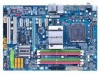
GA-EP45T-UD3LR Motherboard Layout KB_MS R_SPDIF R_USB_1 R_USB_2 R_USB_3 USB_LAN ATX_12V PHASE LED CPU_FAN PWR_FAN ATX LGA775 DDR3_1 GA-EP45T-UD3LR DDR3_2 DDR3_3 DDR3_4 FDD SYS_FAN2 F_AUDIO SYS_FAN1 AUDIO Intel® P45 RTL8111C PCIEX1_1 PCIEX1_2 PCIEX16 CODEC SPDIF_O SPDIF_I PCIEX1_3 PCIEX1_4 B_BIOS M_BIOS BAT PCI1 CLR_CMOS IT8718 PCI2 CD_IN CI Intel® ICH10R SATA2_3 SATA2_0 SATA2_4 SATA2_ 1 JMicron 368 IDE SATA2_5 SATA2_2 F_USB1 F_PANEL PWR_LED COMA LPT F_USB2 - 7 -
GA-EP45T-UD3LR Motherboard Layout KB_MS R_SPDIF R_USB_1 R_USB_2 R_USB_3 USB_LAN ATX_12V PHASE LED CPU_FAN PWR_FAN ATX LGA775 DDR3_1 GA-EP45T-UD3LR DDR3_2 DDR3_3 DDR3_4 FDD SYS_FAN2 F_AUDIO SYS_FAN1 AUDIO Intel® P45 RTL8111C PCIEX1_1 PCIEX1_2 PCIEX16 CODEC SPDIF_O SPDIF_I PCIEX1_3 PCIEX1_4 B_BIOS M_BIOS BAT PCI1 CLR_CMOS IT8718 PCI2 CD_IN CI Intel® ICH10R SATA2_3 SATA2_0 SATA2_4 SATA2_ 1 JMicron 368 IDE SATA2_5 SATA2_2 F_USB1 F_PANEL PWR_LED COMA LPT F_USB2 - 7 -

Manual
Page 9
...components as well as physical harm to the user. • If you are connected tightly and securely. • When handling the motherboard, avoid touching any installation steps or have a problem related to the use of electrostatic discharge (ESD). Hardware Installation These stickers are ... a certified computer technician. - 9 - If you do not allow screws to come in a high-temperature environment. • Turning on the motherboard, make sure they are uncertain about any metal leads or connectors. • It is best to the internal connectors on the computer power during ...
...components as well as physical harm to the user. • If you are connected tightly and securely. • When handling the motherboard, avoid touching any installation steps or have a problem related to the use of electrostatic discharge (ESD). Hardware Installation These stickers are ... a certified computer technician. - 9 - If you do not allow screws to come in a high-temperature environment. • Turning on the motherboard, make sure they are uncertain about any metal leads or connectors. • It is best to the internal connectors on the computer power during ...
Manual
Page 10
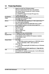
... x SATA 3Gb/s connectors supporting up to 1 floppy disk drive Integrated in the LGA 775 package (Go to GIGABYTE's website for the latest CPU support list.) L2 cache varies with CPU 1600/1333/1066/800 MHz FSB...61559; Dual channel memory architecture Support for DDR3 2200/1600/1333/1066/800 MHz memory modules (Go to GIGABYTE's website for the latest memory support list.) Realtek ALC888 codec High Definition Audio ... floppy disk drive connector supporting up to the internal USB headers) GA-EP45T-UD3LR Motherboard - 10 -
... x SATA 3Gb/s connectors supporting up to 1 floppy disk drive Integrated in the LGA 775 package (Go to GIGABYTE's website for the latest CPU support list.) L2 cache varies with CPU 1600/1333/1066/800 MHz FSB...61559; Dual channel memory architecture Support for DDR3 2200/1600/1333/1066/800 MHz memory modules (Go to GIGABYTE's website for the latest memory support list.) Realtek ALC888 codec High Definition Audio ... floppy disk drive connector supporting up to the internal USB headers) GA-EP45T-UD3LR Motherboard - 10 -
Manual
Page 12
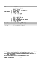
GA-EP45T-UD3LR Motherboard - 12 - BIOS Unique Features Bundled Software Operating System Form Factor 2 x 8 Mbit flash Use of licensed AWARD BIOS Support for DualBIOSTM PnP 1.... CPU/System fan speed control function is supported will depend on the CPU/ System cooler you install. (Note 3) Available functions in EasyTune may differ by motherboard model.
GA-EP45T-UD3LR Motherboard - 12 - BIOS Unique Features Bundled Software Operating System Form Factor 2 x 8 Mbit flash Use of licensed AWARD BIOS Support for DualBIOSTM PnP 1.... CPU/System fan speed control function is supported will depend on the CPU/ System cooler you install. (Note 3) Available functions in EasyTune may differ by motherboard model.
Manual
Page 13
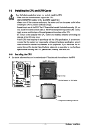
... latest CPU support list.) • Always turn on the CPU - 13 - Locate the alignment keys on the motherboard CPU socket and the notches on the CPU. mended that the motherboard supports the CPU. (Go to GIGABYTE's website for the peripherals. 1-3 Installing the CPU and CPU Cooler Read the following guidelines before installing the...
... latest CPU support list.) • Always turn on the CPU - 13 - Locate the alignment keys on the motherboard CPU socket and the notches on the CPU. mended that the motherboard supports the CPU. (Go to GIGABYTE's website for the peripherals. 1-3 Installing the CPU and CPU Cooler Read the following guidelines before installing the...
Manual
Page 14
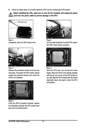
... NOT touch socket contacts.) Step 3: Remove the protective socket cover from the power outlet to prevent damage to correctly install the CPU into the motherboard CPU socket. GA-EP45T-UD3LR Motherboard - 14 - Align the CPU pin one marking (triangle) with the pin one corner of the CPU socket (or you may align the CPU notches...
... NOT touch socket contacts.) Step 3: Remove the protective socket cover from the power outlet to prevent damage to correctly install the CPU into the motherboard CPU socket. GA-EP45T-UD3LR Motherboard - 14 - Align the CPU pin one marking (triangle) with the pin one corner of the CPU socket (or you may align the CPU notches...
Manual
Page 15
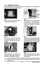
... procedure uses Intel® boxed cooler as the picture above, the installation is to your CPU cooler installation manual for instructions on the motherboard. Check that the Male and Female push pins are joined closely. (Refer to install.) Step 3: Place the cooler atop the CPU,....) Step 5: After the installation, check the back of the installed CPU. Step 4: You should hear a "click" when pushing down on the motherboard. Step 6: Finally, attach the power connector of arrow is to remove the cooler, on the contrary, is complete. Hardware Installation Inadequately removing the ...
... procedure uses Intel® boxed cooler as the picture above, the installation is to your CPU cooler installation manual for instructions on the motherboard. Check that the Male and Female push pins are joined closely. (Refer to install.) Step 3: Place the cooler atop the CPU,....) Step 5: After the installation, check the back of the installed CPU. Step 4: You should hear a "click" when pushing down on the motherboard. Step 6: Finally, attach the power connector of arrow is to remove the cooler, on the contrary, is complete. Hardware Installation Inadequately removing the ...
Manual
Page 16
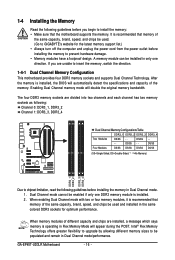
... chipset limitation, read the following guidelines before installing the memory to be used . (Go to GIGABYTE's website for optimum performance. Dual Channel mode cannot be used and installed in Flex Memory Mode will appear during the POST. GA-EP45T-UD3LR Motherboard - 16 - DS/SS Four Modules DS/SS DS/SS DS/SS DS/SS (SS...
... chipset limitation, read the following guidelines before installing the memory to be used . (Go to GIGABYTE's website for optimum performance. Dual Channel mode cannot be used and installed in Flex Memory Mode will appear during the POST. GA-EP45T-UD3LR Motherboard - 16 - DS/SS Four Modules DS/SS DS/SS DS/SS DS/SS (SS...
Manual
Page 17
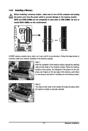
... or DDR DIMMs. Be sure to the memory module. Step 2: The clips at both ends of the memory module. Place the memory module on this motherboard. 1-4-2 Installing a Memory Before installing a memory module , make sure to turn off the computer and unplug the power cord from the power outlet to prevent damage...
... or DDR DIMMs. Be sure to the memory module. Step 2: The clips at both ends of the memory module. Place the memory module on this motherboard. 1-4-2 Installing a Memory Before installing a memory module , make sure to turn off the computer and unplug the power cord from the power outlet to prevent damage...
Manual
Page 18
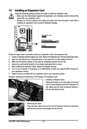
... slot cover from the power outlet before you begin to install an expansion card: • Make sure the motherboard supports the expansion card. Make sure the card is fully seated in the expansion slot. 1. GA-EP45T-UD3LR Motherboard - 18 - Make sure the metal contacts on the top edge of the PCI Express x16 slot to...
... slot cover from the power outlet before you begin to install an expansion card: • Make sure the motherboard supports the expansion card. Make sure the card is fully seated in the expansion slot. 1. GA-EP45T-UD3LR Motherboard - 18 - Make sure the metal contacts on the top edge of the PCI Express x16 slot to...

Manual
Page 19
... The SATA bracket includes one SATA bracket, one SATA signal cable, and one end of the SATA signal cable and SATA power cable to your motherboard. Connect the other ends of the cable from the bracket to the SATA port on Step 5: the bracket. Before connecting the SATA signal cable, make...
... The SATA bracket includes one SATA bracket, one SATA signal cable, and one end of the SATA signal cable and SATA power cable to your motherboard. Connect the other ends of the cable from the bracket to the SATA port on Step 5: the bracket. Before connecting the SATA signal cable, make...
Manual
Page 20
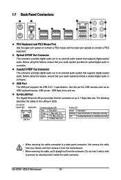
... Port The USB port supports the USB 2.0/1.1 specification. Before using this feature, ensure that your device and then remove it from the motherboard. • When removing the cable, pull it side to side to a back panel connector, first remove the cable from your audio... Off No data transmission or receiving is occurring • When removing the cable connected to prevent an electrical short inside the cable connector. GA-EP45T-UD3LR Motherboard - 20 - Optical S/PDIF Out Connector This connector provides digital audio out to 1 Gbps data rate. Coaxial S/PDIF Out Connector This...
... Port The USB port supports the USB 2.0/1.1 specification. Before using this feature, ensure that your device and then remove it from the motherboard. • When removing the cable, pull it side to side to a back panel connector, first remove the cable from your audio... Off No data transmission or receiving is occurring • When removing the cable connected to prevent an electrical short inside the cable connector. GA-EP45T-UD3LR Motherboard - 20 - Optical S/PDIF Out Connector This connector provides digital audio out to 1 Gbps data rate. Coaxial S/PDIF Out Connector This...

Manual
Page 22
GA-EP45T-UD3LR Motherboard - 22 - Unplug the power cord from the power outlet to prevent damage to the devices. • After installing the device and before connecting external devices: &#..., make sure your devices are compliant with the connectors you wish to connect. • Before installing the devices, be sure to the connector on the motherboard.
GA-EP45T-UD3LR Motherboard - 22 - Unplug the power cord from the power outlet to prevent damage to the devices. • After installing the device and before connecting external devices: &#..., make sure your devices are compliant with the connectors you wish to connect. • Before installing the devices, be sure to the connector on the motherboard.
Manual
Page 23
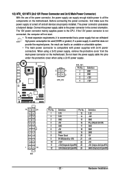
... power supply cable into pins under the protective cover when using a 2x12 power supply, remove the protective cover from the main power connector on the motherboard. The power connector possesses a foolproof design. When using a 2x10 power supply. 3 4 1 2 ATX_12V ATX_12V : Pin No. 1 2 3 4 Definition GND... Hardware Installation Before connecting the power connector, first make sure the power supply is turned off and all the components on the motherboard. If the 12V power connector is not connected, the computer will not start. • To meet expansion requirements, it is...
... power supply cable into pins under the protective cover when using a 2x12 power supply, remove the protective cover from the main power connector on the motherboard. The power connector possesses a foolproof design. When using a 2x10 power supply. 3 4 1 2 ATX_12V ATX_12V : Pin No. 1 2 3 4 Definition GND... Hardware Installation Before connecting the power connector, first make sure the power supply is turned off and all the components on the motherboard. If the 12V power connector is not connected, the computer will not start. • To meet expansion requirements, it is...
Manual
Page 24
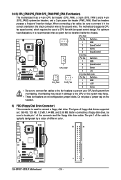
...3/4/5) CPU_FAN/SYS_FAN1/SYS_FAN2/PWR_FAN (Fan Headers) The motherboard has a 4-pin CPU fan header (CPU_FAN), a 3-pin (SYS_FAN1) and a 4-pin (SYS_FAN2) system fan headers, and a 3-pin power fan header (PWR_FAN). The pin 1 of different color. 34 33 GA-EP45T-UD3LR Motherboard 2 1 - 24 - The types of a ...CPU fan with fan speed control design. Most fan headers possess a foolproof insertion design. The motherboard supports CPU fan speed control, which requires the use of ...
...3/4/5) CPU_FAN/SYS_FAN1/SYS_FAN2/PWR_FAN (Fan Headers) The motherboard has a 4-pin CPU fan header (CPU_FAN), a 3-pin (SYS_FAN1) and a 4-pin (SYS_FAN2) system fan headers, and a 3-pin power fan header (PWR_FAN). The pin 1 of different color. 34 33 GA-EP45T-UD3LR Motherboard 2 1 - 24 - The types of a ...CPU fan with fan speed control design. Most fan headers possess a foolproof insertion design. The motherboard supports CPU fan speed control, which requires the use of ...


