Manual
Page 1
GA-EP45-UD3LR/ GA-EP45-UD3L LGA775 socket motherboard for Intel® CoreTM processor family/ Intel® Pentium® processor family/Intel® Celeron® processor family User's Manual Rev. 1101 12ME-EP45UD3L-1101R
GA-EP45-UD3LR/ GA-EP45-UD3L LGA775 socket motherboard for Intel® CoreTM processor family/ Intel® Pentium® processor family/Intel® Celeron® processor family User's Manual Rev. 1101 12ME-EP45UD3L-1101R
Manual
Page 2
Motherboard GA-EP45-UD3LR/GA-EP45-UD3L Oct. 8, 2008 Motherboard GA-EP45-UD3LR/ GA-EP45-UD3L Oct. 8, 2008
Motherboard GA-EP45-UD3LR/GA-EP45-UD3L Oct. 8, 2008 Motherboard GA-EP45-UD3LR/ GA-EP45-UD3L Oct. 8, 2008

Manual
Page 4
Table of Contents Box Contents ...6 OptionalItems...6 GA-EP45-UD3LR/GA-EP45-UD3L Motherboard Layout 7 Block Diagram...8 Chapter 1 Hardware Installation 9 1-1 Installation Precautions 9 1-2 Product Specifications 10 1-3 Installing the CPU and CPU Cooler 13 1-3-1 Installing the CPU 13 1-3-2 Installing the ...
Table of Contents Box Contents ...6 OptionalItems...6 GA-EP45-UD3LR/GA-EP45-UD3L Motherboard Layout 7 Block Diagram...8 Chapter 1 Hardware Installation 9 1-1 Installation Precautions 9 1-2 Product Specifications 10 1-3 Installing the CPU and CPU Cooler 13 1-3-1 Installing the CPU 13 1-3-2 Installing the ...
Manual
Page 5
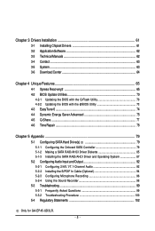
... (Optional 94 5-2-3 Configuring Microphone Recording 96 5-2-4 Using the Sound Recorder 98 5-3 Troubleshooting 99 5-3-1 Frequently Asked Questions 99 5-3-2 Troubleshooting Procedure 100 5-4 Regulatory Statements 102 Only for GA-EP45-UD3LR. - 5 -
... (Optional 94 5-2-3 Configuring Microphone Recording 96 5-2-4 Using the Sound Recorder 98 5-3 Troubleshooting 99 5-3-1 Frequently Asked Questions 99 5-3-2 Troubleshooting Procedure 100 5-4 Regulatory Statements 102 Only for GA-EP45-UD3LR. - 5 -
Manual
Page 6
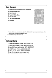
...-2SERPW-0*R) S/PDIF in cable (Part No. 12CR1-1SPDIN-0*R) COM port cable (Part No. 12CF1-1CM001-3*R) LPT port cable (Part No. 12CF1-1LP001-0*R) - 6 - Box Contents GA-EP45-UD3LR or GA-EP45-UD3L motherboard Motherboard driver disk User's Manual Quick Installation Guide One IDE cable Two SATA 3Gb/s cables I/O Shield • The box contents above are subject...
...-2SERPW-0*R) S/PDIF in cable (Part No. 12CR1-1SPDIN-0*R) COM port cable (Part No. 12CF1-1CM001-3*R) LPT port cable (Part No. 12CF1-1LP001-0*R) - 6 - Box Contents GA-EP45-UD3LR or GA-EP45-UD3L motherboard Motherboard driver disk User's Manual Quick Installation Guide One IDE cable Two SATA 3Gb/s cables I/O Shield • The box contents above are subject...
Manual
Page 7
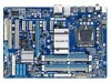
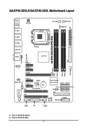
Only for GA-EP45-UD3LR. GA-EP45-UD3LR/GA-EP45-UD3L Motherboard Layout KB_MS R_SPDIF R_USB_1 R_USB_2 R_USB_3 ATX_12V LGA775 CPU_FAN PWR_FAN PHASE LED ATX DDR2_1 GA-EP45-UD3LR/GA-EP45-UD3L DDR2_2 DDR2_3 DDR2_4 FDD SYS_FAN2 USB_LAN F_AUDIO SYS_FAN1 AUDIO Intel® P45 RTL8111C PCIEX1_1 PCIEX1_2 PCIEX16 CODEC SPDIF_O SPDIF_I PCIEX1_3 PCIEX1_4 B_BIOS M_BIOS BAT PCI1 ... CD_IN CI Intel® ICH10R Intel® ICH10 SATA2_3 SATA2_0 SATA2_4 SATA2_ 1 JMicron 368 IDE SATA2_5 SATA2_2 F_USB1 F_PANEL PWR_LED COMA LPT F_USB2 Only for GA-EP45-UD3L. - 7 -
Only for GA-EP45-UD3LR. GA-EP45-UD3LR/GA-EP45-UD3L Motherboard Layout KB_MS R_SPDIF R_USB_1 R_USB_2 R_USB_3 ATX_12V LGA775 CPU_FAN PWR_FAN PHASE LED ATX DDR2_1 GA-EP45-UD3LR/GA-EP45-UD3L DDR2_2 DDR2_3 DDR2_4 FDD SYS_FAN2 USB_LAN F_AUDIO SYS_FAN1 AUDIO Intel® P45 RTL8111C PCIEX1_1 PCIEX1_2 PCIEX16 CODEC SPDIF_O SPDIF_I PCIEX1_3 PCIEX1_4 B_BIOS M_BIOS BAT PCI1 ... CD_IN CI Intel® ICH10R Intel® ICH10 SATA2_3 SATA2_0 SATA2_4 SATA2_ 1 JMicron 368 IDE SATA2_5 SATA2_2 F_USB1 F_PANEL PWR_LED COMA LPT F_USB2 Only for GA-EP45-UD3L. - 7 -
Manual
Page 8
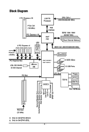
Only for GA-EP45-UD3LR. Block Diagram 1 PCI Express x16 LGA775 Processor CPU CLK+/(400/333/266/200 MHz) PCIe CLK (100 MHz) PCI Express x16 PCIe CLK (100 ... Speaker Out Center/Subwoofer Speaker Out Side Speaker Out MIC Line-Out Line-In SPDIF In SPDIF Out 2 PCI PCI CLK (33 MHz) Only for GA-EP45-UD3L. - 8 -
Only for GA-EP45-UD3LR. Block Diagram 1 PCI Express x16 LGA775 Processor CPU CLK+/(400/333/266/200 MHz) PCIe CLK (100 MHz) PCI Express x16 PCIe CLK (100 ... Speaker Out Center/Subwoofer Speaker Out Side Speaker Out MIC Line-Out Line-In SPDIF In SPDIF Out 2 PCI PCI CLK (33 MHz) Only for GA-EP45-UD3L. - 8 -

Manual
Page 10
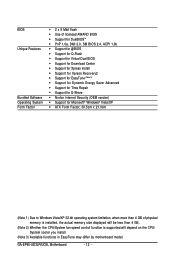
...; Up to 12 USB 2.0/1.1 ports (8 on the back panel, 4 via the USB brackets connected to the internal USB headers) Only for GA-EP45-UD3LR. GA-EP45-UD3LR/UD3L Motherboard - 10 - Support for SATA RAID 0, RAID 1, RAID 5 and RAID 10 JMicron 368 chip: - 1 x IDE connector... 4 x 1.8V DDR2 DIMM sockets supporting up to GIGABYTE's website for the latest memory support list.) Realtek ALC888 codec High Definition Audio 2/4/5.1/7.1-channel Support for S/PDIF In/Out Support for GA-EP45-UD3L. Only for CD In 1 x Realtek 8111C chip...
...; Up to 12 USB 2.0/1.1 ports (8 on the back panel, 4 via the USB brackets connected to the internal USB headers) Only for GA-EP45-UD3LR. GA-EP45-UD3LR/UD3L Motherboard - 10 - Support for SATA RAID 0, RAID 1, RAID 5 and RAID 10 JMicron 368 chip: - 1 x IDE connector... 4 x 1.8V DDR2 DIMM sockets supporting up to GIGABYTE's website for the latest memory support list.) Realtek ALC888 codec High Definition Audio 2/4/5.1/7.1-channel Support for S/PDIF In/Out Support for GA-EP45-UD3L. Only for CD In 1 x Realtek 8111C chip...
Manual
Page 12
GA-EP45-UD3LR/UD3L Motherboard - 12 - BIOS Unique Features Bundled Software Operating System Form Factor 2 x 8 Mbit flash Use of licensed AWARD BIOS Support for DualBIOSTM ...
GA-EP45-UD3LR/UD3L Motherboard - 12 - BIOS Unique Features Bundled Software Operating System Form Factor 2 x 8 Mbit flash Use of licensed AWARD BIOS Support for DualBIOSTM ...

Manual
Page 14
... touch socket contacts.) Step 3: Remove the protective socket cover from the power outlet to prevent damage to correctly install the CPU into its locked position. GA-EP45-UD3LR/UD3L Motherboard - 14 - Step 5: Once the CPU is not installed.) Step 4: Hold the CPU with the socket alignment keys) and gently insert the CPU into...
... touch socket contacts.) Step 3: Remove the protective socket cover from the power outlet to prevent damage to correctly install the CPU into its locked position. GA-EP45-UD3LR/UD3L Motherboard - 14 - Step 5: Once the CPU is not installed.) Step 4: Hold the CPU with the socket alignment keys) and gently insert the CPU into...
Manual
Page 16
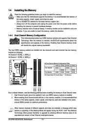
Enabling Dual Channel memory mode will appear during the POST. GA-EP45-UD3LR/UD3L Motherboard - 16 - If you begin to install the memory: • Make sure that the motherboard supports the memory. When memory modules of the memory.... with two or four memory modules, it is installed. 2. Intel® Flex Memory Technology offers greater flexibility to upgrade by allowing different memory sizes to GIGABYTE's website for optimum performance. 1-4 Installing the Memory Read the following guidelines before installing the memory in Dual Channel mode. 1. DS/SS - - It is ...
Enabling Dual Channel memory mode will appear during the POST. GA-EP45-UD3LR/UD3L Motherboard - 16 - If you begin to install the memory: • Make sure that the motherboard supports the memory. When memory modules of the memory.... with two or four memory modules, it is installed. 2. Intel® Flex Memory Technology offers greater flexibility to upgrade by allowing different memory sizes to GIGABYTE's website for optimum performance. 1-4 Installing the Memory Read the following guidelines before installing the memory in Dual Channel mode. 1. DS/SS - - It is ...

Manual
Page 18
... it is fully inserted into the slot. 4. 1-5 Installing an Expansion Card Read the following guidelines before installing an expansion card to prevent hardware damage. GA-EP45-UD3LR/UD3L Motherboard - 18 - Make sure the metal contacts on the top edge of the PCI Express x16 slot to release the card and then pull the...
... it is fully inserted into the slot. 4. 1-5 Installing an Expansion Card Read the following guidelines before installing an expansion card to prevent hardware damage. GA-EP45-UD3LR/UD3L Motherboard - 18 - Make sure the metal contacts on the top edge of the PCI Express x16 slot to release the card and then pull the...
Manual
Page 20
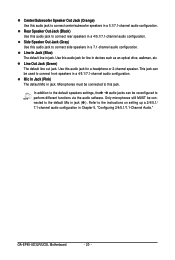
... Speaker Out Jack (Gray) Use this audio jack to connect rear speakers in a 4/5.1/7.1-channel audio configuration. Line Out Jack (Green) The default line out jack. GA-EP45-UD3LR/UD3L Motherboard - 20 - Rear Speaker Out Jack (Black) Use this audio jack to connect side speakers in a 7.1-channel audio configuration. Use this audio jack for...
... Speaker Out Jack (Gray) Use this audio jack to connect rear speakers in a 4/5.1/7.1-channel audio configuration. Line Out Jack (Green) The default line out jack. GA-EP45-UD3LR/UD3L Motherboard - 20 - Rear Speaker Out Jack (Black) Use this audio jack to connect side speakers in a 7.1-channel audio configuration. Use this audio jack for...
Manual
Page 22
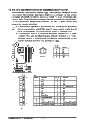
... 3.3V -12V GND PS_ON(soft On/Off) GND GND GND -5V +5V +5V +5V (Only for 2x12-pinATX) GND (Only for 2x12-pin ATX) GA-EP45-UD3LR/UD3L Motherboard - 22 - The 12V power connector mainly supplies power to an unstable or unbootable system. • The main power connector is used that can withstand...
... 3.3V -12V GND PS_ON(soft On/Off) GND GND GND -5V +5V +5V +5V (Only for 2x12-pinATX) GND (Only for 2x12-pin ATX) GA-EP45-UD3LR/UD3L Motherboard - 22 - The 12V power connector mainly supplies power to an unstable or unbootable system. • The main power connector is used that can withstand...
Manual
Page 24
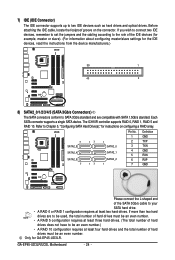
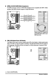
The ICH10R controller supports RAID 0, RAID 1, RAID 5 and RAID 10. GA-EP45-UD3LR/UD3L Motherboard - 24 - If you wish to connect two IDE devices, remember to set the jumpers and the cabling according to the role of the IDE ... to SATA 3Gb/s standard and are to be used, the total number of hard drives does not have to Chapter 5, "Configuring SATA Hard Drive(s)," for GA-EP45-UD3LR. Each SATA connector supports a single SATA device. Refer to be an even number. If more than two hard drives are compatible with SATA 1.5Gb...
The ICH10R controller supports RAID 0, RAID 1, RAID 5 and RAID 10. GA-EP45-UD3LR/UD3L Motherboard - 24 - If you wish to connect two IDE devices, remember to set the jumpers and the cabling according to the role of the IDE ... to SATA 3Gb/s standard and are to be used, the total number of hard drives does not have to Chapter 5, "Configuring SATA Hard Drive(s)," for GA-EP45-UD3LR. Each SATA connector supports a single SATA device. Refer to be an even number. If more than two hard drives are compatible with SATA 1.5Gb...
Manual
Page 25
... indicate system power status. Definition 1 MPD+ 1 2 MPD- 3 MPD- Pin No. Hardware Installation System Status LED S0 On S1 Blinking S3/S4/S5 Off Only for GA-EP45-UD3L. - 25 - The LED keeps blinking when the system is in S3/S4 sleep state or powered off when the system is operating. The LED is...
... indicate system power status. Definition 1 MPD+ 1 2 MPD- 3 MPD- Pin No. Hardware Installation System Status LED S0 On S1 Blinking S3/S4/S5 Off Only for GA-EP45-UD3L. - 25 - The LED keeps blinking when the system is in S3/S4 sleep state or powered off when the system is operating. The LED is...
Manual
Page 26
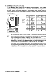
... signals will make the device unable to this header. Definition Pin No. If your chassis front panel audio module to work or even damage it. GA-EP45-UD3LR/UD3L Motherboard - 26 - Incorrect connection between the module connector and the motherboard header will be present on each wire instead of the front and back...
... signals will make the device unable to this header. Definition Pin No. If your chassis front panel audio module to work or even damage it. GA-EP45-UD3LR/UD3L Motherboard - 26 - Incorrect connection between the module connector and the motherboard header will be present on each wire instead of the front and back...

Manual
Page 28
Definition 1 CD-L 2 GND 3 GND 4 CD-R 1 13) SPDIF_I (S/PDIF In Heade) This header supports digital S/PDIF in and can connect to an audio device that came with your optical drive to the header. Definition 1 Power 2 SPDIFI 3 GND GA-EP45-UD3LR/UD3L Motherboard - 28 - For purchasing the optional S/PDIF in cable. Pin No. 12) CD_IN (CD In Connector) You may connect the audio cable that supports digital audio out via an optional S/PDIF in cable, please contact the local dealer. 1 Pin No.
Definition 1 CD-L 2 GND 3 GND 4 CD-R 1 13) SPDIF_I (S/PDIF In Heade) This header supports digital S/PDIF in and can connect to an audio device that came with your optical drive to the header. Definition 1 Power 2 SPDIFI 3 GND GA-EP45-UD3LR/UD3L Motherboard - 28 - For purchasing the optional S/PDIF in cable. Pin No. 12) CD_IN (CD In Connector) You may connect the audio cable that supports digital audio out via an optional S/PDIF in cable, please contact the local dealer. 1 Pin No.
Manual
Page 30
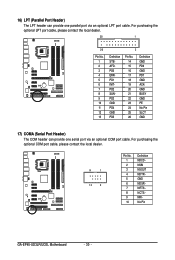
... optional COM port cable, please contact the local dealer. 9 1 10 2 Pin No. 1 2 3 4 5 6 7 8 9 10 Definition NDCD NSIN NSOUT NDTR GND NDSR NRTS NCTS NRI No Pin GA-EP45-UD3LR/UD3L Motherboard - 30 - For purchasing the optional LPT port cable, please contact the local dealer. 25 1 26 Pin No. 1 2 3 4 5 6 7 8 9 10 11 12 13 2 Definition STBAFDPD0...
... optional COM port cable, please contact the local dealer. 9 1 10 2 Pin No. 1 2 3 4 5 6 7 8 9 10 Definition NDCD NSIN NSOUT NDTR GND NDSR NRTS NCTS NRI No Pin GA-EP45-UD3LR/UD3L Motherboard - 30 - For purchasing the optional LPT port cable, please contact the local dealer. 25 1 26 Pin No. 1 2 3 4 5 6 7 8 9 10 11 12 13 2 Definition STBAFDPD0...
Manual
Page 32
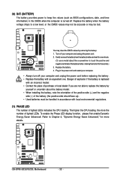
... face up). • Used batteries must be lost. Gently remove the battery from the battery holder and wait for more the number of lighted LEDs. GA-EP45-UD3LR/UD3L Motherboard - 32 - Turn off your computer and unplug the power cord. 2. The higher the CPU loading, the more details. To enable the Phase LED...
... face up). • Used batteries must be lost. Gently remove the battery from the battery holder and wait for more the number of lighted LEDs. GA-EP45-UD3LR/UD3L Motherboard - 32 - Turn off your computer and unplug the power cord. 2. The higher the CPU loading, the more details. To enable the Phase LED...


