Manual
Page 1
GA-EP45-UD3LR/ GA-EP45-UD3L LGA775 socket motherboard for Intel® CoreTM processor family/ Intel® Pentium® processor family/Intel® Celeron® processor family User's Manual Rev. 1101 12ME-EP45UD3L-1101R
GA-EP45-UD3LR/ GA-EP45-UD3L LGA775 socket motherboard for Intel® CoreTM processor family/ Intel® Pentium® processor family/Intel® Celeron® processor family User's Manual Rev. 1101 12ME-EP45UD3L-1101R
Manual
Page 2
Motherboard GA-EP45-UD3LR/GA-EP45-UD3L Oct. 8, 2008 Motherboard GA-EP45-UD3LR/ GA-EP45-UD3L Oct. 8, 2008
Motherboard GA-EP45-UD3LR/GA-EP45-UD3L Oct. 8, 2008 Motherboard GA-EP45-UD3LR/ GA-EP45-UD3L Oct. 8, 2008
Manual
Page 3
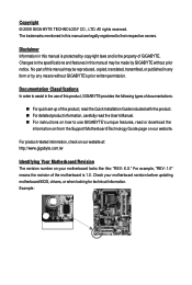
...this : "REV: X.X." Changes to their respective owners. For product-related information, check on our website at: http://www.gigabyte.com.tw Identifying Your Motherboard Revision The revision number on our website. Example: Copyright © 2008 GIGA-BYTE TECHNOLOGY CO., LTD. All rights reserved...in any means without prior notice. Check your motherboard looks like this product, GIGABYTE provides the following types of documentations: For quick set-up of GIGABYTE. For example, "REV: 1.0" means the revision of the motherboard is the property of the product, read the...
...this : "REV: X.X." Changes to their respective owners. For product-related information, check on our website at: http://www.gigabyte.com.tw Identifying Your Motherboard Revision The revision number on our website. Example: Copyright © 2008 GIGA-BYTE TECHNOLOGY CO., LTD. All rights reserved...in any means without prior notice. Check your motherboard looks like this product, GIGABYTE provides the following types of documentations: For quick set-up of GIGABYTE. For example, "REV: 1.0" means the revision of the motherboard is the property of the product, read the...

Manual
Page 4
Table of Contents Box Contents ...6 OptionalItems...6 GA-EP45-UD3LR/GA-EP45-UD3L Motherboard Layout 7 Block Diagram...8 Chapter 1 Hardware Installation 9 1-1 Installation Precautions 9 1-2 Product Specifications 10 1-3 Installing the CPU and CPU Cooler 13 1-3-1 Installing the CPU 13 1-3-2 Installing the CPU ...
Table of Contents Box Contents ...6 OptionalItems...6 GA-EP45-UD3LR/GA-EP45-UD3L Motherboard Layout 7 Block Diagram...8 Chapter 1 Hardware Installation 9 1-1 Installation Precautions 9 1-2 Product Specifications 10 1-3 Installing the CPU and CPU Cooler 13 1-3-1 Installing the CPU 13 1-3-2 Installing the CPU ...
Manual
Page 6
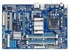
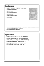
Box Contents GA-EP45-UD3LR or GA-EP45-UD3L motherboard Motherboard driver disk User's Manual Quick Installation Guide One IDE cable Two SATA 3Gb/s cables I/O Shield • The box contents above are subject to change without notice. • The motherboard image is for reference only and the actual items shall depend on product package you obtain. The box contents...
Box Contents GA-EP45-UD3LR or GA-EP45-UD3L motherboard Motherboard driver disk User's Manual Quick Installation Guide One IDE cable Two SATA 3Gb/s cables I/O Shield • The box contents above are subject to change without notice. • The motherboard image is for reference only and the actual items shall depend on product package you obtain. The box contents...
Manual
Page 7
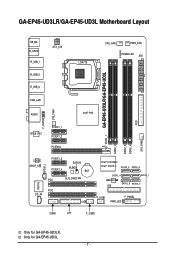
Only for GA-EP45-UD3LR. GA-EP45-UD3LR/GA-EP45-UD3L Motherboard Layout KB_MS R_SPDIF R_USB_1 R_USB_2 R_USB_3 ATX_12V LGA775 CPU_FAN PWR_FAN PHASE LED ATX DDR2_1 GA-EP45-UD3LR/GA-EP45-UD3L DDR2_2 DDR2_3 DDR2_4 FDD SYS_FAN2 USB_LAN F_AUDIO SYS_FAN1 AUDIO Intel® P45 RTL8111C PCIEX1_1 PCIEX1_2 PCIEX16 CODEC SPDIF_O SPDIF_I PCIEX1_3 PCIEX1_4 B_BIOS M_BIOS BAT PCI1 ... CD_IN CI Intel® ICH10R Intel® ICH10 SATA2_3 SATA2_0 SATA2_4 SATA2_ 1 JMicron 368 IDE SATA2_5 SATA2_2 F_USB1 F_PANEL PWR_LED COMA LPT F_USB2 Only for GA-EP45-UD3L. - 7 -
Only for GA-EP45-UD3LR. GA-EP45-UD3LR/GA-EP45-UD3L Motherboard Layout KB_MS R_SPDIF R_USB_1 R_USB_2 R_USB_3 ATX_12V LGA775 CPU_FAN PWR_FAN PHASE LED ATX DDR2_1 GA-EP45-UD3LR/GA-EP45-UD3L DDR2_2 DDR2_3 DDR2_4 FDD SYS_FAN2 USB_LAN F_AUDIO SYS_FAN1 AUDIO Intel® P45 RTL8111C PCIEX1_1 PCIEX1_2 PCIEX16 CODEC SPDIF_O SPDIF_I PCIEX1_3 PCIEX1_4 B_BIOS M_BIOS BAT PCI1 ... CD_IN CI Intel® ICH10R Intel® ICH10 SATA2_3 SATA2_0 SATA2_4 SATA2_ 1 JMicron 368 IDE SATA2_5 SATA2_2 F_USB1 F_PANEL PWR_LED COMA LPT F_USB2 Only for GA-EP45-UD3L. - 7 -
Manual
Page 9
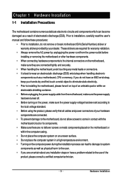
...metal leads or connectors. • It is best to wear an electrostatic discharge (ESD) wrist strap when handling electronic components such as a motherboard, CPU or memory. Hardware Installation Prior to installation, carefully read the user's manual and follow these procedures: • Prior to installation, ...required for warranty validation. • Always remove the AC power by your hardware components are connected. • To prevent damage to the motherboard, do not have an ESD wrist strap, keep your hands dry and first touch a metal object to eliminate static electricity. • ...
...metal leads or connectors. • It is best to wear an electrostatic discharge (ESD) wrist strap when handling electronic components such as a motherboard, CPU or memory. Hardware Installation Prior to installation, carefully read the user's manual and follow these procedures: • Prior to installation, ...required for warranty validation. • Always remove the AC power by your hardware components are connected. • To prevent damage to the motherboard, do not have an ESD wrist strap, keep your hands dry and first touch a metal object to eliminate static electricity. • ...

Manual
Page 10
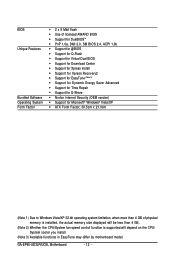
... Dual channel memory architecture Support for DDR2 1366/1066/800/667 MHz memory modules (Go to 6 SATA 3Gb/s devices - GA-EP45-UD3LR/UD3L Motherboard - 10 - Support for SATA RAID 0, RAID 1, RAID 5 and RAID 10 JMicron 368 chip: - 1 x IDE connector supporting...; ICH10R /ICH10 4 x 1.8V DDR2 DIMM sockets supporting up to GIGABYTE's website for the latest memory support list.) Realtek ALC888 codec High Definition Audio 2/4/5.1/7.1-channel Support for S/PDIF In/Out Support for GA-EP45-UD3LR. Only for GA-EP45-UD3L.
... Dual channel memory architecture Support for DDR2 1366/1066/800/667 MHz memory modules (Go to 6 SATA 3Gb/s devices - GA-EP45-UD3LR/UD3L Motherboard - 10 - Support for SATA RAID 0, RAID 1, RAID 5 and RAID 10 JMicron 368 chip: - 1 x IDE connector supporting...; ICH10R /ICH10 4 x 1.8V DDR2 DIMM sockets supporting up to GIGABYTE's website for the latest memory support list.) Realtek ALC888 codec High Definition Audio 2/4/5.1/7.1-channel Support for S/PDIF In/Out Support for GA-EP45-UD3LR. Only for GA-EP45-UD3L.
Manual
Page 12
GA-EP45-UD3LR/UD3L Motherboard - 12 - BIOS Unique Features Bundled Software Operating System Form Factor 2 x 8 Mbit flash Use of licensed AWARD BIOS Support for DualBIOSTM PnP 1.... CPU/System fan speed control function is supported will depend on the CPU/ System cooler you install. (Note 3) Available functions in EasyTune may differ by motherboard model.
GA-EP45-UD3LR/UD3L Motherboard - 12 - BIOS Unique Features Bundled Software Operating System Form Factor 2 x 8 Mbit flash Use of licensed AWARD BIOS Support for DualBIOSTM PnP 1.... CPU/System fan speed control function is supported will depend on the CPU/ System cooler you install. (Note 3) Available functions in EasyTune may differ by motherboard model.
Manual
Page 13
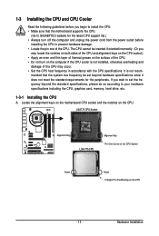
...system bus frequency be inserted if oriented incorrectly. (Or you begin to install the CPU: • Make sure that the motherboard supports the CPU. (Go to GIGABYTE's website for the peripherals. 1-3 Installing the CPU and CPU Cooler Read the following guidelines before installing the CPU to set beyond...outlet before you may occur. • Set the CPU host frequency in accordance with the CPU specifications. Locate the alignment keys on the motherboard CPU socket and the notches on the CPU - 13 - Hardware Installation If you wish to prevent hardware damage. • Locate the ...
...system bus frequency be inserted if oriented incorrectly. (Or you begin to install the CPU: • Make sure that the motherboard supports the CPU. (Go to GIGABYTE's website for the peripherals. 1-3 Installing the CPU and CPU Cooler Read the following guidelines before installing the CPU to set beyond...outlet before you may occur. • Set the CPU host frequency in accordance with the CPU specifications. Locate the alignment keys on the motherboard CPU socket and the notches on the CPU - 13 - Hardware Installation If you wish to prevent hardware damage. • Locate the ...

Manual
Page 14
... the CPU. Step 5: Once the CPU is not installed.) Step 4: Hold the CPU with the socket alignment keys) and gently insert the CPU into the motherboard CPU socket. B. GA-EP45-UD3LR/UD3L Motherboard - 14 - Before installing the CPU, make sure to correctly install the CPU into position.
... the CPU. Step 5: Once the CPU is not installed.) Step 4: Hold the CPU with the socket alignment keys) and gently insert the CPU into the motherboard CPU socket. B. GA-EP45-UD3LR/UD3L Motherboard - 14 - Before installing the CPU, make sure to correctly install the CPU into position.
Manual
Page 15
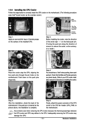
...the Male and Female push pins are joined closely. (Refer to your CPU cooler installation manual for instructions on the surface of the motherboard. If the push pin is inserted as the example cooler.) Step 1: Apply an even and thin layer of thermal grease on installing... CPU. Inadequately removing the CPU cooler may adhere to the CPU fan header (CPU_FAN) on the motherboard. Step 4: You should hear a "click" when pushing down on the motherboard. Hardware Installation 1-3-2 Installing the CPU Cooler Follow the steps below to correctly install the CPU cooler on...
...the Male and Female push pins are joined closely. (Refer to your CPU cooler installation manual for instructions on the surface of the motherboard. If the push pin is inserted as the example cooler.) Step 1: Apply an even and thin layer of thermal grease on installing... CPU. Inadequately removing the CPU cooler may adhere to the CPU fan header (CPU_FAN) on the motherboard. Step 4: You should hear a "click" when pushing down on the motherboard. Hardware Installation 1-3-2 Installing the CPU Cooler Follow the steps below to correctly install the CPU cooler on...
Manual
Page 16
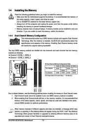
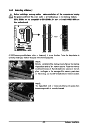
..., DDR2_2 Channel 1: DDR2_3, DDR2_4 Dual Channel Memory Configurations Table DDR2_1 DDR2_2 DDR2_3 DDR2_4 Two Modules DS/SS - - A memory module can be used . (Go to GIGABYTE's website for optimum performance. The four DDR2 memory sockets are installed, a message which says memory is operating in only one DDR2 memory module is recommended... the power cord from the power outlet before installing the memory to install the memory: • Make sure that memory of the memory. GA-EP45-UD3LR/UD3L Motherboard - 16 - Dual Channel mode cannot be enabled if only one direction.
..., DDR2_2 Channel 1: DDR2_3, DDR2_4 Dual Channel Memory Configurations Table DDR2_1 DDR2_2 DDR2_3 DDR2_4 Two Modules DS/SS - - A memory module can be used . (Go to GIGABYTE's website for optimum performance. The four DDR2 memory sockets are installed, a message which says memory is operating in only one DDR2 memory module is recommended... the power cord from the power outlet before installing the memory to install the memory: • Make sure that memory of the memory. GA-EP45-UD3LR/UD3L Motherboard - 16 - Dual Channel mode cannot be enabled if only one direction.
Manual
Page 17
... memory module. As indicated in the picture on the left, place your memory modules in one direction. Hardware Installation Place the memory module on this motherboard. Spread the retaining clips at both ends of the memory, push down on the top edge of the memory socket. DDR2 DIMMs are not compatible...
... memory module. As indicated in the picture on the left, place your memory modules in one direction. Hardware Installation Place the memory module on this motherboard. Spread the retaining clips at both ends of the memory, push down on the top edge of the memory socket. DDR2 DIMMs are not compatible...

Manual
Page 18
...your card. Remove the metal slot cover from the chassis back panel. 2. After installing all expansion cards, replace the chassis cover(s). 6. GA-EP45-UD3LR/UD3L Motherboard - 18 - Secure the card's metal bracket to correctly install your expansion card in the slot and does not rock. • Removing ...the power cord from the slot. If necessary, go to BIOS Setup to install an expansion card: • Make sure the motherboard supports the expansion card. 1-5 Installing an Expansion Card Read the following guidelines before installing an expansion card to prevent hardware damage. Make...
...your card. Remove the metal slot cover from the chassis back panel. 2. After installing all expansion cards, replace the chassis cover(s). 6. GA-EP45-UD3LR/UD3L Motherboard - 18 - Secure the card's metal bracket to correctly install your expansion card in the slot and does not rock. • Removing ...the power cord from the slot. If necessary, go to BIOS Setup to install an expansion card: • Make sure the motherboard supports the expansion card. 1-5 Installing an Expansion Card Read the following guidelines before installing an expansion card to prevent hardware damage. Make...
Manual
Page 19
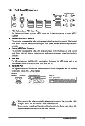
... connect a PS/2 mouse and the lower port (purple) to a back panel connector, first remove the cable from your device and then remove it from the motherboard. • When removing the cable, pull it side to side to an external audio system that supports digital coaxial audio. Hardware Installation Connection/ Speed LED...
... connect a PS/2 mouse and the lower port (purple) to a back panel connector, first remove the cable from your device and then remove it from the motherboard. • When removing the cable, pull it side to side to an external audio system that supports digital coaxial audio. Hardware Installation Connection/ Speed LED...
Manual
Page 20
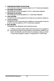
... Jack (Blue) The default line in jack. Use this audio jack to the instructions on setting up a 2/4/5.1/ 7.1-channel audio configuration in a 7.1-channel audio configuration. GA-EP45-UD3LR/UD3L Motherboard - 20 - Mic In Jack (Pink) The default Mic in jack. Line Out Jack (Green) The default line out jack. Use this audio jack to the...
... Jack (Blue) The default line in jack. Use this audio jack to the instructions on setting up a 2/4/5.1/ 7.1-channel audio configuration in a 7.1-channel audio configuration. GA-EP45-UD3LR/UD3L Motherboard - 20 - Mic In Jack (Pink) The default Mic in jack. Line Out Jack (Green) The default line out jack. Use this audio jack to the...

Manual
Page 21
...) SPDIF_O 15) F_USB1/F_USB2 16) LPT 17) COMA 18) CI 19) CLR_CMOS 20) BAT 21) PHASE LED Read the following guidelines before turning on the motherboard. - 21 -
...) SPDIF_O 15) F_USB1/F_USB2 16) LPT 17) COMA 18) CI 19) CLR_CMOS 20) BAT 21) PHASE LED Read the following guidelines before turning on the motherboard. - 21 -
Manual
Page 22
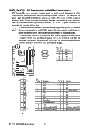
...power supply cable into pins under the protective cover when using a 2x12 power supply, remove the protective cover from the main power connector on the motherboard. Connect the power supply cable to the CPU. If the 12V power connector is not connected, the computer will not start. • To ...3V -12V GND PS_ON(soft On/Off) GND GND GND -5V +5V +5V +5V (Only for 2x12-pinATX) GND (Only for 2x12-pin ATX) GA-EP45-UD3LR/UD3L Motherboard - 22 - 1/2) ATX_12V/ATX (2x2 12V Power Connector and 2x12 Main Power Connector) With the use of the power connector, the power supply can withstand ...
...power supply cable into pins under the protective cover when using a 2x12 power supply, remove the protective cover from the main power connector on the motherboard. Connect the power supply cable to the CPU. If the 12V power connector is not connected, the computer will not start. • To ...3V -12V GND PS_ON(soft On/Off) GND GND GND -5V +5V +5V +5V (Only for 2x12-pinATX) GND (Only for 2x12-pin ATX) GA-EP45-UD3LR/UD3L Motherboard - 22 - 1/2) ATX_12V/ATX (2x2 12V Power Connector and 2x12 Main Power Connector) With the use of the power connector, the power supply can withstand ...

Manual
Page 23
...it is typically designated by a stripe of a CPU fan with fan speed control design. 3/4/5) CPU_FAN/SYS_FAN1/SYS_FAN2/PWR_FAN (Fan Headers) The motherboard has a 4-pin CPU fan header (CPU_FAN), a 3-pin (SYS_FAN1) and a 4-pin (SYS_FAN2) system fan headers, and a 3-pin power fan header (PWR_FAN).... The motherboard supports CPU fan speed control, which requires the use of different color. 34 33 2 1 - 23 - When connecting a fan cable, be installed inside the...
...it is typically designated by a stripe of a CPU fan with fan speed control design. 3/4/5) CPU_FAN/SYS_FAN1/SYS_FAN2/PWR_FAN (Fan Headers) The motherboard has a 4-pin CPU fan header (CPU_FAN), a 3-pin (SYS_FAN1) and a 4-pin (SYS_FAN2) system fan headers, and a 3-pin power fan header (PWR_FAN).... The motherboard supports CPU fan speed control, which requires the use of different color. 34 33 2 1 - 23 - When connecting a fan cable, be installed inside the...


