Manual
Page 3
...mentioned in this manual are legally registered to use GIGABYTE's unique features, read or download the information on/from the Support\Motherboard\Technology Guide page on your motherboard revision before updating motherboard BIOS, drivers, or when looking for technical information. ...Changes to the specifications and features in this manual may be made by any form or by GIGABYTE without GIGABYTE's prior written permission. Copyright © 2008 GIGA...
...mentioned in this manual are legally registered to use GIGABYTE's unique features, read or download the information on/from the Support\Motherboard\Technology Guide page on your motherboard revision before updating motherboard BIOS, drivers, or when looking for technical information. ...Changes to the specifications and features in this manual may be made by any form or by GIGABYTE without GIGABYTE's prior written permission. Copyright © 2008 GIGA...

Manual
Page 4
Table of Contents Box Contents ...6 OptionalItems...6 GA-EP45-UD3LR/GA-EP45-UD3L Motherboard Layout 7 Block Diagram...8 Chapter 1 Hardware Installation 9 1-1 Installation Precautions 9 1-2 Product Specifications 10 1-3 Installing the CPU and ...Installing an Expansion Card 18 1-6 Back Panel Connectors 19 1-7 Internal Connectors 21 Chapter 2 BIOS Setup 33 2-1 Startup Screen 34 2-2 The Main Menu 35 2-3 MB Intelligent Tweaker(M.I.T 37 2-4 Standard CMOS Features 45 2-5 Advanced BIOS Features 47 2-6 IntegratedPeripherals 50 2-7 Power Management Setup 53 2-8 PnP/PCI Configurations 55 ...
Table of Contents Box Contents ...6 OptionalItems...6 GA-EP45-UD3LR/GA-EP45-UD3L Motherboard Layout 7 Block Diagram...8 Chapter 1 Hardware Installation 9 1-1 Installation Precautions 9 1-2 Product Specifications 10 1-3 Installing the CPU and ...Installing an Expansion Card 18 1-6 Back Panel Connectors 19 1-7 Internal Connectors 21 Chapter 2 BIOS Setup 33 2-1 Startup Screen 34 2-2 The Main Menu 35 2-3 MB Intelligent Tweaker(M.I.T 37 2-4 Standard CMOS Features 45 2-5 Advanced BIOS Features 47 2-6 IntegratedPeripherals 50 2-7 Power Management Setup 53 2-8 PnP/PCI Configurations 55 ...
Manual
Page 5
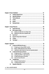
...Technical Manuals 62 3-4 Contact ...63 3-5 System ...63 3-6 Download Center 64 Chapter 4 Unique Features 65 4-1 Xpress Recovery2 65 4-2 BIOS Update Utilities 70 4-2-1 Updating the BIOS with the Q-Flash Utility 70 4-2-2 Updating the BIOS with the @BIOS Utility 73 4-3 EasyTune 6 ...74 4-4 Dynamic Energy Saver Advanced 75 4-5 Q-Share ...77 4-6 Time Repair ...78 Chapter 5 Appendix ... Recording 96 5-2-4 Using the Sound Recorder 98 5-3 Troubleshooting 99 5-3-1 Frequently Asked Questions 99 5-3-2 Troubleshooting Procedure 100 5-4 Regulatory Statements 102 Only for GA-EP45-UD3LR. - 5 -
...Technical Manuals 62 3-4 Contact ...63 3-5 System ...63 3-6 Download Center 64 Chapter 4 Unique Features 65 4-1 Xpress Recovery2 65 4-2 BIOS Update Utilities 70 4-2-1 Updating the BIOS with the Q-Flash Utility 70 4-2-2 Updating the BIOS with the @BIOS Utility 73 4-3 EasyTune 6 ...74 4-4 Dynamic Energy Saver Advanced 75 4-5 Q-Share ...77 4-6 Time Repair ...78 Chapter 5 Appendix ... Recording 96 5-2-4 Using the Sound Recorder 98 5-3 Troubleshooting 99 5-3-1 Frequently Asked Questions 99 5-3-2 Troubleshooting Procedure 100 5-4 Regulatory Statements 102 Only for GA-EP45-UD3LR. - 5 -
Manual
Page 8
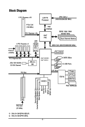
...; ICH10 Dual BIOS 6 SATA 3Gb/s 12 USB Ports PCI Bus CODEC LPC Bus IT8718 Floppy LPT Port COM Port PS/2 KB/Mouse Surround Speaker Out Center/Subwoofer Speaker Out Side Speaker Out MIC Line-Out Line-In SPDIF In SPDIF Out 2 PCI PCI CLK (33 MHz) Only for GA-EP45-UD3L. - 8 - Only for GA-EP45-UD3LR.
...; ICH10 Dual BIOS 6 SATA 3Gb/s 12 USB Ports PCI Bus CODEC LPC Bus IT8718 Floppy LPT Port COM Port PS/2 KB/Mouse Surround Speaker Out Center/Subwoofer Speaker Out Side Speaker Out MIC Line-Out Line-In SPDIF In SPDIF Out 2 PCI PCI CLK (33 MHz) Only for GA-EP45-UD3L. - 8 - Only for GA-EP45-UD3LR.
Manual
Page 12
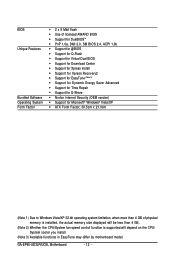
... Software Operating System Form Factor 2 x 8 Mbit flash Use of licensed AWARD BIOS Support for DualBIOSTM PnP 1.0a, DMI 2.0, SM BIOS 2.4, ACPI 1.0b Support for @BIOS Support for Q-Flash Support for Virtual Dual BIOS Support for Download Center Support for Xpress Install Support for Xpress... fan speed control function is supported will depend on the CPU/ System cooler you install. (Note 3) Available functions in EasyTune may differ by motherboard model. GA-EP45-UD3LR/UD3L Motherboard - 12 -
... Software Operating System Form Factor 2 x 8 Mbit flash Use of licensed AWARD BIOS Support for DualBIOSTM PnP 1.0a, DMI 2.0, SM BIOS 2.4, ACPI 1.0b Support for @BIOS Support for Q-Flash Support for Virtual Dual BIOS Support for Download Center Support for Xpress Install Support for Xpress... fan speed control function is supported will depend on the CPU/ System cooler you install. (Note 3) Available functions in EasyTune may differ by motherboard model. GA-EP45-UD3LR/UD3L Motherboard - 12 -
Manual
Page 16
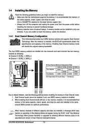
... (SS=Single-Sided, DS=Double-Sided, "- -"=No Memory) DDR2_1 DDR2_2 DDR2_3 DDR2_4 Due to GIGABYTE's website for optimum performance. A memory module can be enabled if only one direction. GA-EP45-UD3LR/UD3L Motherboard - 16 - DS/SS - - - - It is recommended that memory of the same... capacity, brand, speed, and chips be used . (Go to chipset limitation, read the following guidelines before installing the memory in Dual Channel mode/performance. After the memory is installed, the BIOS...
... (SS=Single-Sided, DS=Double-Sided, "- -"=No Memory) DDR2_1 DDR2_2 DDR2_3 DDR2_4 Due to GIGABYTE's website for optimum performance. A memory module can be enabled if only one direction. GA-EP45-UD3LR/UD3L Motherboard - 16 - DS/SS - - - - It is recommended that memory of the same... capacity, brand, speed, and chips be used . (Go to chipset limitation, read the following guidelines before installing the memory in Dual Channel mode/performance. After the memory is installed, the BIOS...

Manual
Page 18
...: • Installing a Graphics Card: Gently push down on the top edge of the PCI Express x16 slot to make any required BIOS changes for your computer. Turn on the card are completely inserted into the PCI Express x16 slot. PCI Express x1 Slot PCI Express... expansion slot. 1. Secure the card's metal bracket to install an expansion card: • Make sure the motherboard supports the expansion card. GA-EP45-UD3LR/UD3L Motherboard - 18 - 1-5 Installing an Expansion Card Read the following guidelines before installing an expansion card to prevent hardware damage. Make sure the...
...: • Installing a Graphics Card: Gently push down on the top edge of the PCI Express x16 slot to make any required BIOS changes for your computer. Turn on the card are completely inserted into the PCI Express x16 slot. PCI Express x1 Slot PCI Express... expansion slot. 1. Secure the card's metal bracket to install an expansion card: • Make sure the motherboard supports the expansion card. GA-EP45-UD3LR/UD3L Motherboard - 18 - 1-5 Installing an Expansion Card Read the following guidelines before installing an expansion card to prevent hardware damage. Make sure the...

Manual
Page 27
... • MSG (Message/Power/Sleep LED, Yellow): System Status LED Connects to the power status indicator on when the system is detected, the BIOS may configure the way to turn off when the system is reading or writing data. • RES (Reset Switch, Green): Connects to the ...power switch, reset switch, power LED, hard drive activity LED, speaker and etc. When connecting your system using the power switch (refer to Chapter 2, "BIOS Setup," "Power Management Setup," for information about beep codes. • HD (Hard Drive Activity LED, Blue) Connects to the hard drive activity LED ...
... • MSG (Message/Power/Sleep LED, Yellow): System Status LED Connects to the power status indicator on when the system is detected, the BIOS may configure the way to turn off when the system is reading or writing data. • RES (Reset Switch, Green): Connects to the ...power switch, reset switch, power LED, hard drive activity LED, speaker and etc. When connecting your system using the power switch (refer to Chapter 2, "BIOS Setup," "Power Management Setup," for information about beep codes. • HD (Hard Drive Activity LED, Blue) Connects to the hard drive activity LED ...
Manual
Page 31
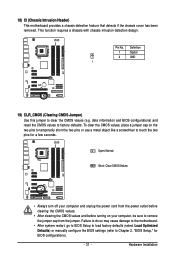
... values (e.g. Failure to do so may cause damage to the motherboard. • After system restart, go to BIOS Setup to load factory defaults (select Load Optimized Defaults) or manually configure the BIOS settings (refer to Chapter 2, "BIOS Setup," for a few seconds. Definition 1 Signal 2 GND 1 19) CLR_CMOS (Clearing CMOS Jumper) Use this jumper to... chassis cover has been removed. Open: Normal Short: Clear CMOS Values • Always turn off your computer, be sure to touch the two pins for BIOS configurations). - 31 -
... values (e.g. Failure to do so may cause damage to the motherboard. • After system restart, go to BIOS Setup to load factory defaults (select Load Optimized Defaults) or manually configure the BIOS settings (refer to Chapter 2, "BIOS Setup," for a few seconds. Definition 1 Signal 2 GND 1 19) CLR_CMOS (Clearing CMOS Jumper) Use this jumper to... chassis cover has been removed. Open: Normal Short: Clear CMOS Values • Always turn off your computer, be sure to touch the two pins for BIOS configurations). - 31 -
Manual
Page 32
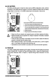
...21) PHASE LED The number of lighted LEDs indicates the CPU loading. Gently remove the battery from the battery holder and wait for one . GA-EP45-UD3LR/UD3L Motherboard - 32 - Plug in the power cord and restart your computer. • Always turn off your computer and unplug the power cord....of lighted LEDs. To enable the Phase LED display function, please first enable Dynamic Energy Saver Advanced. Refer to keep the values (such as BIOS configurations, date, and time information) in accordance with an equivalent one minute. (Or use a metal object like a screwdriver to replace the...
...21) PHASE LED The number of lighted LEDs indicates the CPU loading. Gently remove the battery from the battery holder and wait for one . GA-EP45-UD3LR/UD3L Motherboard - 32 - Plug in the power cord and restart your computer. • Always turn off your computer and unplug the power cord....of lighted LEDs. To enable the Phase LED display function, please first enable Dynamic Energy Saver Advanced. Refer to keep the values (such as BIOS configurations, date, and time information) in accordance with an equivalent one minute. (Or use a metal object like a screwdriver to replace the...
Manual
Page 33
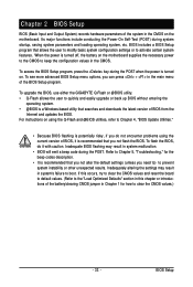
...not alter the default settings (unless you not flash the BIOS. BIOS includes a BIOS Setup program that you need to) to prevent system instability or other unexpected results. To upgrade the BIOS, use either the GIGABYTE Q-Flash or @BIOS utility. • Q-Flash allows the user to quickly and... easily upgrade or back up BIOS without entering the operating system. • @BIOS is turned off, the battery on the motherboard ...
...not alter the default settings (unless you not flash the BIOS. BIOS includes a BIOS Setup program that you need to) to prevent system instability or other unexpected results. To upgrade the BIOS, use either the GIGABYTE Q-Flash or @BIOS utility. • Q-Flash allows the user to quickly and... easily upgrade or back up BIOS without entering the operating system. • @BIOS is turned off, the battery on the motherboard ...

Manual
Page 34
... change the first boot device setting as needed. : Q-FLASH Press the key to access the Q-Flash utility directly without entering BIOS Setup. GA-EP45-UD3LR/UD3L Motherboard - 34 - After system restart, the device boot order will directly boot from the device configured in Boot Menu is... effective for subsequent access to set the first boot device without having to enter BIOS Setup first. To exit Boot Menu, press . For more...
... change the first boot device setting as needed. : Q-FLASH Press the key to access the Q-Flash utility directly without entering BIOS Setup. GA-EP45-UD3LR/UD3L Motherboard - 34 - After system restart, the device boot order will directly boot from the device configured in Boot Menu is... effective for subsequent access to set the first boot device without having to enter BIOS Setup first. To exit Boot Menu, press . For more...
Manual
Page 35
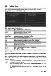
...Main Menu. Use arrow keys to move among the items and press to accept or enter a sub-menu. (Sample BIOS Version: GA-EP45-UD3L E19) CMOS Setup Utility-Copyright (C) 1984-2008 Award Software MB Intelligent Tweaker(M.I.T.) Standard CMOS Features Advanced... BIOS Features Integrated Peripherals Power Management Setup PnP/PCI Configurations PC Health Status Load Fail-...
...Main Menu. Use arrow keys to move among the items and press to accept or enter a sub-menu. (Sample BIOS Version: GA-EP45-UD3L E19) CMOS Setup Utility-Copyright (C) 1984-2008 Award Software MB Intelligent Tweaker(M.I.T.) Standard CMOS Features Advanced... BIOS Features Integrated Peripherals Power Management Setup PnP/PCI Configurations PC Health Status Load Fail-...

Manual
Page 36
...frequency and voltages of your system becomes unstable and you have loaded the BIOS default settings, you can use the SPACE key) and then press to erase the default profile name, use this task.) GA-EP45-UD3LR/UD3L Motherboard - 36 - First enter the profile name (to complete. ... F12 : Load CMOS from a profile created before, without the hassles of reconfiguring the BIOS settings. Pressing to the confirmation message will exit BIOS Setup. (Pressing can also...
...frequency and voltages of your system becomes unstable and you have loaded the BIOS default settings, you can use the SPACE key) and then press to erase the default profile name, use this task.) GA-EP45-UD3LR/UD3L Motherboard - 36 - First enter the profile name (to complete. ... F12 : Load CMOS from a profile created before, without the hassles of reconfiguring the BIOS settings. Pressing to the confirmation message will exit BIOS Setup. (Pressing can also...
Manual
Page 37
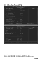
... appears only if you install a CPU that supports this feature. (Note 2) This item appears only if you install a memory module that supports this feature. - 37 - BIOS Setup
... appears only if you install a CPU that supports this feature. (Note 2) This item appears only if you install a memory module that supports this feature. - 37 - BIOS Setup
Manual
Page 38
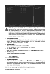
...) Allows you to alter the clock ratio for automated system reboot, or clear the CMOS values to reset the board to be configurable. GA-EP45-UD3LR/UD3L Motherboard - 38 - This page is for advanced users only and we recommend you to boot. If this feature. Options are: Auto ...Graphics Booster Robust Graphics Booster (R.G.B.) helps to automatically set in system's failure to increase the CPU clock ratio set the R.G.B. Auto allows the BIOS to enhance the performance of these components. >>> MCH/ICH MCH Core MCH Reference ICH I/O ICH Core >>> DRAM DRAM Voltage CMOS Setup Utility-...
...) Allows you to alter the clock ratio for automated system reboot, or clear the CMOS values to reset the board to be configurable. GA-EP45-UD3LR/UD3L Motherboard - 38 - This page is for advanced users only and we recommend you to boot. If this feature. Options are: Auto ...Graphics Booster Robust Graphics Booster (R.G.B.) helps to automatically set in system's failure to increase the CPU clock ratio set the R.G.B. Auto allows the BIOS to enhance the performance of these components. >>> MCH/ICH MCH Core MCH Reference ICH I/O ICH Core >>> DRAM DRAM Voltage CMOS Setup Utility-...
Manual
Page 39
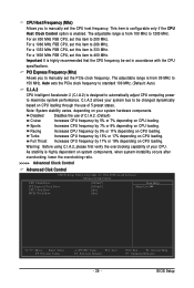
... overclocking capability of 5 preset states. Auto sets the PCIe clock frequency to standard 100 MHz. (Default: Auto) C.I.A.2 CPU Intelligent Accelerator 2 (C.I .A.2 allows your system hardware components. BIOS Setup Note: System stability varies, depending on your system bus to be set in accordance with the CPU specifications. Turbo Increases CPU frequency by 17...
... overclocking capability of 5 preset states. Auto sets the PCIe clock frequency to standard 100 MHz. (Default: Auto) C.I.A.2 CPU Intelligent Accelerator 2 (C.I .A.2 allows your system hardware components. BIOS Setup Note: System stability varies, depending on your system bus to be set in accordance with the CPU specifications. Turbo Increases CPU frequency by 17...

Manual
Page 40
... prior to the CPU clock. Options are : 700mV, 800mV (default), 900mV, 1000mV. Extreme Memory Profile (X.M.P.) (Note) Allows the BIOS to fix the chipset frequency at its best performance level. Options are : Auto (default), Manual. (Note) This item appears only... good performance level. (Default) Extreme Lets the system operate at system bootup. Options are : 700mV, 800mV (default), 900mV, 1000mV. GA-EP45-UD3LR/UD3L Motherboard - 40 - Options are : 0ps~750ps. (Default: 0ps) ******** DRAM Performance Control ******** Performance Enhance Allows the system to enhance...
... prior to the CPU clock. Options are : 700mV, 800mV (default), 900mV, 1000mV. Extreme Memory Profile (X.M.P.) (Note) Allows the BIOS to fix the chipset frequency at its best performance level. Options are : Auto (default), Manual. (Note) This item appears only... good performance level. (Default) Extreme Lets the system operate at system bootup. Options are : 700mV, 800mV (default), 900mV, 1000mV. GA-EP45-UD3LR/UD3L Motherboard - 40 - Options are : 0ps~750ps. (Default: 0ps) ******** DRAM Performance Control ******** Performance Enhance Allows the system to enhance...
Manual
Page 41
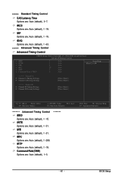
...] [Press Enter] Move Enter: Select F5: Previous Values +/-/PU/PD: Value F10: Save F6: Fail-Safe Defaults ******** Advanced Timing Control tRRD Options are : Auto (default), 3~7. BIOS Setup >>>>> Standard Timing Control CAS Latency Time Options are : Auto (default), 1~15. tRFC Options are : Auto (default), 1~15. tRP Options are : Auto (default), 1~255. tWTR...
...] [Press Enter] Move Enter: Select F5: Previous Values +/-/PU/PD: Value F10: Save F6: Fail-Safe Defaults ******** Advanced Timing Control tRRD Options are : Auto (default), 3~7. BIOS Setup >>>>> Standard Timing Control CAS Latency Time Options are : Auto (default), 1~15. tRFC Options are : Auto (default), 1~15. tRP Options are : Auto (default), 1~255. tWTR...
Manual
Page 43
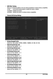
... Options are : Auto (default), +8~-7. Ctrl Driving Pull-Up Level Options are : Auto (default), +8~-7. Clk Driving Pull-Down Level Options are : Auto (default), +8~-7. Auto Lets the BIOS decide whether to enable this function. (Default) Disabled Disables this function to enhance memory compatibility. Data Driving Pull-Up Level Options are : Auto (default), +8~-7. - 43...
... Options are : Auto (default), +8~-7. Ctrl Driving Pull-Up Level Options are : Auto (default), +8~-7. Clk Driving Pull-Down Level Options are : Auto (default), +8~-7. Auto Lets the BIOS decide whether to enable this function. (Default) Disabled Disables this function to enhance memory compatibility. Data Driving Pull-Up Level Options are : Auto (default), +8~-7. - 43...


