

Manual
Page 1
GA-EP45-EXTREME LGA775 socket motherboard for Intel® CoreTM processor family/ Intel® Pentium® processor family/Intel® Celeron® processor family User's Manual Rev. 1001 12ME-EP45EXT-1001R
GA-EP45-EXTREME LGA775 socket motherboard for Intel® CoreTM processor family/ Intel® Pentium® processor family/Intel® Celeron® processor family User's Manual Rev. 1001 12ME-EP45EXT-1001R

Manual
Page 3
... The revision number on our website. The trademarks mentioned in any form or by GIGABYTE without GIGABYTE's prior written permission. Check your motherboard looks like this manual are legally registered to GIGABYTE UNITED INC. Example: sive global distributor of the motherboard is the property of this manual may be made by any means without prior...
... The revision number on our website. The trademarks mentioned in any form or by GIGABYTE without GIGABYTE's prior written permission. Check your motherboard looks like this manual are legally registered to GIGABYTE UNITED INC. Example: sive global distributor of the motherboard is the property of this manual may be made by any means without prior...
Manual
Page 4
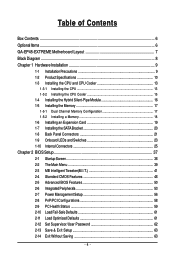
Table of Contents Box Contents ...6 OptionalItems ...6 GA-EP45-EXTREME Motherboard Layout 7 Block Diagram ...8 Chapter 1 Hardware Installation 9 1-1 Installation Precautions 9 1-2 Product Specifications 10 1-3 Installing the CPU and CPU Cooler 13 1-3-1 Installing the CPU 13 1-3-2 Installing the CPU ...
Table of Contents Box Contents ...6 OptionalItems ...6 GA-EP45-EXTREME Motherboard Layout 7 Block Diagram ...8 Chapter 1 Hardware Installation 9 1-1 Installation Precautions 9 1-2 Product Specifications 10 1-3 Installing the CPU and CPU Cooler 13 1-3-1 Installing the CPU 13 1-3-2 Installing the CPU ...

Manual
Page 6
...PDIF in cable (Part No. 12CR1-1SPDIN-01R) COM port cable (Part No. 12CF1-1CM001-32R) - 6 - The box contents are for reference only. Box Contents GA-EP45-EXTREME motherboard Motherboard driver disk User's Manual Quick Installation Guide Intel® LGA775 CPU Installation Guide One IDE cable and one floppy disk drive cable Four SATA 3Gb...shield One 2-port IEEE 1394a bracket One Hybrid Silent-Pipe module kit • The box contents above are subject to change without notice. • The motherboard image is for reference only and the actual items shall depend on product package you obtain.
...PDIF in cable (Part No. 12CR1-1SPDIN-01R) COM port cable (Part No. 12CF1-1CM001-32R) - 6 - The box contents are for reference only. Box Contents GA-EP45-EXTREME motherboard Motherboard driver disk User's Manual Quick Installation Guide Intel® LGA775 CPU Installation Guide One IDE cable and one floppy disk drive cable Four SATA 3Gb...shield One 2-port IEEE 1394a bracket One Hybrid Silent-Pipe module kit • The box contents above are subject to change without notice. • The motherboard image is for reference only and the actual items shall depend on product package you obtain.

Manual
Page 7
GA-EP45-EXTREME Motherboard Layout KB_MS R_SPDIF ATX_12V_2X CMOS_SW R_USB LGA775 CPU_FAN F_LED1/2/3/4/5 CPU_LED1/2/3 CT_LED1/2 ATX PHASE LED PWR_FAN GA-EP45- EXTREME USB_LAN2 USB_LAN1 RTL8111C BAT DDR_LED1/2/3 AUDIO Intel® P45 F_AUDIO PCIEX1_1 FDD RTL8111C PCI1 NB_LED1/2/3 NBT_LED1/2 DDR2_1 DDR2_2 DDR2_3 DDR2_4 SATA2_4 SATA2_2 SATA2_5 SATA2_3 CD_IN ...
GA-EP45-EXTREME Motherboard Layout KB_MS R_SPDIF ATX_12V_2X CMOS_SW R_USB LGA775 CPU_FAN F_LED1/2/3/4/5 CPU_LED1/2/3 CT_LED1/2 ATX PHASE LED PWR_FAN GA-EP45- EXTREME USB_LAN2 USB_LAN1 RTL8111C BAT DDR_LED1/2/3 AUDIO Intel® P45 F_AUDIO PCIEX1_1 FDD RTL8111C PCI1 NB_LED1/2/3 NBT_LED1/2 DDR2_1 DDR2_2 DDR2_3 DDR2_4 SATA2_4 SATA2_2 SATA2_5 SATA2_3 CD_IN ...
Manual
Page 9
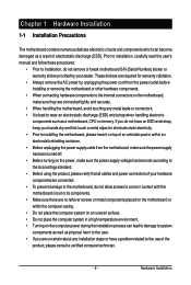
... been turned off. • Before turning on the power, make sure they are connected tightly and securely. • When handling the motherboard, avoid touching any metal leads or connectors. • It is best to wear an electrostatic discharge (ESD) wrist strap when handling electronic...not have an ESD wrist strap, keep your hands dry and first touch a metal object to eliminate static electricity. • Prior to installing the motherboard, please have a problem related to the use of the product, please consult a certified computer technician. - 9 - Prior to installation, carefully read...
... been turned off. • Before turning on the power, make sure they are connected tightly and securely. • When handling the motherboard, avoid touching any metal leads or connectors. • It is best to wear an electrostatic discharge (ESD) wrist strap when handling electronic...not have an ESD wrist strap, keep your hands dry and first touch a metal object to eliminate static electricity. • Prior to installing the motherboard, please have a problem related to the use of the product, please consult a certified computer technician. - 9 - Prior to installation, carefully read...

Manual
Page 10
TSB43AB23 chip Š Up to 3 IEEE 1394a ports (via the IEEE 1394a brackets connected to the internal IEEE 1394a headers) GA-EP45-EXTREME Motherboard - 10 - Support for Teaming Š 1 x PCI Express x16 slot (Note 3) Š 1 x PCI Express x8 slot (The PCIEX16_1 and PCIEX8_1 slots ... 8 GB of system memory (Note 1) Š Dual channel memory architecture Š Support for DDR2 1200/1066/800/667 MHz memory modules (Go to GIGABYTE's website for the latest memory support list.) Š Realtek ALC889A codec Š High Definition Audio Š 2/4/5.1/7.1-channel Š Support for Dolby® ...
TSB43AB23 chip Š Up to 3 IEEE 1394a ports (via the IEEE 1394a brackets connected to the internal IEEE 1394a headers) GA-EP45-EXTREME Motherboard - 10 - Support for Teaming Š 1 x PCI Express x16 slot (Note 3) Š 1 x PCI Express x8 slot (The PCIEX16_1 and PCIEX8_1 slots ... 8 GB of system memory (Note 1) Š Dual channel memory architecture Š Support for DDR2 1200/1066/800/667 MHz memory modules (Go to GIGABYTE's website for the latest memory support list.) Š Realtek ALC889A codec Š High Definition Audio Š 2/4/5.1/7.1-channel Š Support for Dolby® ...

Manual
Page 12
When it in EasyTune may differ by motherboard model. GA-EP45-EXTREME Motherboard - 12 - When both of physical memory is installed, the actual memory size displayed will be sure to install it is supported will operate at x8 ...
When it in EasyTune may differ by motherboard model. GA-EP45-EXTREME Motherboard - 12 - When both of physical memory is installed, the actual memory size displayed will be sure to install it is supported will operate at x8 ...
Manual
Page 13
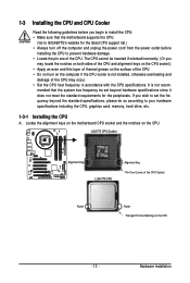
.... • Locate the pin one of the CPU Socket Notch Notch Triangle Pin One Marking on the CPU - 13 - Locate the alignment keys on the motherboard CPU socket and the notches on the computer if the CPU cooler is not recom- LGA775 CPU Socket Alignment Key LGA 775 CPU Alignment Key... thermal grease on the surface of the CPU may occur. • Set the CPU host frequency in accordance with the CPU specifications. mended that the motherboard supports the CPU. (Go to GIGABYTE's website for the peripherals.
.... • Locate the pin one of the CPU Socket Notch Notch Triangle Pin One Marking on the CPU - 13 - Locate the alignment keys on the motherboard CPU socket and the notches on the computer if the CPU cooler is not recom- LGA775 CPU Socket Alignment Key LGA 775 CPU Alignment Key... thermal grease on the surface of the CPU may occur. • Set the CPU host frequency in accordance with the CPU specifications. mended that the motherboard supports the CPU. (Go to GIGABYTE's website for the peripherals.

Manual
Page 14
... socket. CPU Socket Lever Step 1: Completely raise the CPU socket lever. Step 3: Lift the metal load plate on the CPU socket. GA-EP45-EXTREME Motherboard - 14 - Follow the steps below to the CPU. Step 4: Hold the CPU with the socket alignment keys) and gently insert the CPU into position. B. Before ...
... socket. CPU Socket Lever Step 1: Completely raise the CPU socket lever. Step 3: Lift the metal load plate on the CPU socket. GA-EP45-EXTREME Motherboard - 14 - Follow the steps below to the CPU. Step 4: Hold the CPU with the socket alignment keys) and gently insert the CPU into position. B. Before ...

Manual
Page 15
...following procedure uses Intel® boxed cooler as the picture above, the installation is to your CPU cooler installation manual for instructions on the motherboard. Direction of the Arrow Sign on the Male Push Pin Male Push Pin The Top of Female Push Pin Female Push Pin Step 2:... the cooler, on the contrary, is complete. Step 6: Finally, attach the power connector of the motherboard. Step 4: You should hear a "click" when pushing down on the push pins diagonally. Use extreme care when removing the CPU cooler because the thermal grease/tape between the CPU cooler and CPU may...
...following procedure uses Intel® boxed cooler as the picture above, the installation is to your CPU cooler installation manual for instructions on the motherboard. Direction of the Arrow Sign on the Male Push Pin Male Push Pin The Top of Female Push Pin Female Push Pin Step 2:... the cooler, on the contrary, is complete. Step 6: Finally, attach the power connector of the motherboard. Step 4: You should hear a "click" when pushing down on the push pins diagonally. Use extreme care when removing the CPU cooler because the thermal grease/tape between the CPU cooler and CPU may...

Manual
Page 16
... 1. Step 2: Position the heatpipe underneath the heatsink of the Hybrid Silent-Pipe module into the tunnel of thermal grease on the motherboard, be sure to connect it grooves. Step 4: The picture on the left shows that four screws are fastened to the heatsink and ...steps below to install the Hybrid Silent-Pipe module: Step 1: Apply an even thin layer of the North Bridge heasink base. Thermal grease 3. GA-EP45-EXTREME Motherboard - 16 - A Philip's screwdriver 2. Screws included with a screw to complete the installation. 1-4 Installing the Hybrid Silent-Pipe Module Read the...
... 1. Step 2: Position the heatpipe underneath the heatsink of the Hybrid Silent-Pipe module into the tunnel of thermal grease on the motherboard, be sure to connect it grooves. Step 4: The picture on the left shows that four screws are fastened to the heatsink and ...steps below to install the Hybrid Silent-Pipe module: Step 1: Apply an even thin layer of the North Bridge heasink base. Thermal grease 3. GA-EP45-EXTREME Motherboard - 16 - A Philip's screwdriver 2. Screws included with a screw to complete the installation. 1-4 Installing the Hybrid Silent-Pipe Module Read the...

Manual
Page 17
...the same capacity, brand, speed, and chips be enabled if only one direction. Dual Channel mode cannot be used . (Go to GIGABYTE's website for the latest memory support list.) • Always turn off the computer and unplug the power cord from the power outlet before...says memory is installed. 2. The four DDR2 memory sockets are unable to insert the memory, switch the direction. 1-5-1 Dual Channel Memory Configuration This motherboard provides four DDR2 memory sockets and supports Dual Channel Technology. DS/SS - - When enabling Dual Channel mode with two or four memory modules,...
...the same capacity, brand, speed, and chips be enabled if only one direction. Dual Channel mode cannot be used . (Go to GIGABYTE's website for the latest memory support list.) • Always turn off the computer and unplug the power cord from the power outlet before...says memory is installed. 2. The four DDR2 memory sockets are unable to insert the memory, switch the direction. 1-5-1 Dual Channel Memory Configuration This motherboard provides four DDR2 memory sockets and supports Dual Channel Technology. DS/SS - - When enabling Dual Channel mode with two or four memory modules,...

Manual
Page 18
... unplug the power cord from the power outlet to prevent damage to install DDR2 DIMMs on this motherboard. Spread the retaining clips at both ends of the socket will snap into the memory socket. GA-EP45-EXTREME Motherboard - 18 - Follow the steps below to correctly install your memory modules in the picture on the left...
... unplug the power cord from the power outlet to prevent damage to install DDR2 DIMMs on this motherboard. Spread the retaining clips at both ends of the socket will snap into the memory socket. GA-EP45-EXTREME Motherboard - 18 - Follow the steps below to correctly install your memory modules in the picture on the left...

Manual
Page 19
... turn off the computer and unplug the power cord from the power outlet before you begin to install an expansion card: • Make sure the motherboard supports the expansion card. PCI Express x1 Slot PCI Express x16/x8/x4 Slot PCI Slot Follow the steps below to correctly install your expansion...
... turn off the computer and unplug the power cord from the power outlet before you begin to install an expansion card: • Make sure the motherboard supports the expansion card. PCI Express x1 Slot PCI Express x16/x8/x4 Slot PCI Slot Follow the steps below to correctly install your expansion...

Manual
Page 20
Follow the steps below to install the SATA bracket: Step 1: Locate one SATA power cable. nector on your motherboard. Step 3: Step 4: Connect the power Plug one end of the cable from the bracket to the SATA port on the bracket. Before connecting the SATA ... cable to prevent damage to hardware. • Insert the SATA signal cable and SATA power cable securely into to the chassis back panel with a screw. GA-EP45-EXTREME Motherboard - 20 -
Follow the steps below to install the SATA bracket: Step 1: Locate one SATA power cable. nector on your motherboard. Step 3: Step 4: Connect the power Plug one end of the cable from the bracket to the SATA port on the bracket. Before connecting the SATA ... cable to prevent damage to hardware. • Insert the SATA signal cable and SATA power cable securely into to the chassis back panel with a screw. GA-EP45-EXTREME Motherboard - 20 -

Manual
Page 21
... an USB keyboard/mouse, USB printer, USB flash drive and etc. Before using this feature, ensure that your device and then remove it from the motherboard. • When removing the cable, pull it side to side to a back panel connector, first remove the cable from your audio system provides a coaxial digital...
... an USB keyboard/mouse, USB printer, USB flash drive and etc. Before using this feature, ensure that your device and then remove it from the motherboard. • When removing the cable, pull it side to side to a back panel connector, first remove the cable from your audio system provides a coaxial digital...

Manual
Page 22
...) The default Mic in devices such as an optical drive, walkman, etc. Use this audio jack to connect center/subwoofer speakers in a 5.1/7.1-channel audio configuration. GA-EP45-EXTREME Motherboard - 22 - Center/Subwoofer Speaker Out Jack (Orange) Use this audio jack for line in jack.
...) The default Mic in devices such as an optical drive, walkman, etc. Use this audio jack to connect center/subwoofer speakers in a 5.1/7.1-channel audio configuration. GA-EP45-EXTREME Motherboard - 22 - Center/Subwoofer Speaker Out Jack (Orange) Use this audio jack for line in jack.

Manual
Page 23
... indicate on which indicate the overvoltage level of the CPU, memory, North Bridge, and South Bridge. Hardware Installation 1-9 Onboard LEDs and Switches Overvoltage LEDs This motherboard contains 4 sets of overvoltage LEDs which level the CPU is below 60oC; CPU (CPU TEMP) Off: Below 60oC CT_LED1: 61~ 80oC (green) CT_LED2: Over 80oC...
... indicate on which indicate the overvoltage level of the CPU, memory, North Bridge, and South Bridge. Hardware Installation 1-9 Onboard LEDs and Switches Overvoltage LEDs This motherboard contains 4 sets of overvoltage LEDs which level the CPU is below 60oC; CPU (CPU TEMP) Off: Below 60oC CT_LED1: 61~ 80oC (green) CT_LED2: Over 80oC...

Manual
Page 24
PW_SW: Power switch RST_SW: Reset switch CMOS_SW: Clearing CMOS switch - 24 - Hardware Installation Quick Switches This motherboard has 3 quick switches: power switch, reset switch and clearing CMOS switch, allowing users to quickly turn on/off or reset the system or clear the CMOS values.
PW_SW: Power switch RST_SW: Reset switch CMOS_SW: Clearing CMOS switch - 24 - Hardware Installation Quick Switches This motherboard has 3 quick switches: power switch, reset switch and clearing CMOS switch, allowing users to quickly turn on/off or reset the system or clear the CMOS values.


