
Manual
Page 9
... an ESD wrist strap, keep your hands dry and first touch a metal object to eliminate static electricity. • Prior to installing the motherboard, please have a problem related to the use of the product, please consult a certified computer technician. - 9 - Chapter 1 Hardware Installation 1-1 Installation Precautions The motherboard contains numerous delicate electronic circuits and...
... an ESD wrist strap, keep your hands dry and first touch a metal object to eliminate static electricity. • Prior to installing the motherboard, please have a problem related to the use of the product, please consult a certified computer technician. - 9 - Chapter 1 Hardware Installation 1-1 Installation Precautions The motherboard contains numerous delicate electronic circuits and...

Manual
Page 22
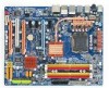
Power Switch Reset Switch Clearing CMOS Switch GA-EP45-DS3P Motherboard - 22 - 1-8 Onboard LEDs and Switches Diagnostic LEDs This motherboard has 7 onboard LEDs controlled by the system BIOS. CPU Memory PCIe x8/x16 PCIe x1/... a device (including PCI and PCIe cards and IDE/SATA devices) works abnormally. The LED will light up during the POST when the components/devices have a problem.
Power Switch Reset Switch Clearing CMOS Switch GA-EP45-DS3P Motherboard - 22 - 1-8 Onboard LEDs and Switches Diagnostic LEDs This motherboard has 7 onboard LEDs controlled by the system BIOS. CPU Memory PCIe x8/x16 PCIe x1/... a device (including PCI and PCIe cards and IDE/SATA devices) works abnormally. The LED will light up during the POST when the components/devices have a problem.

Manual
Page 29
...the system is detected at system startup. The LED is off (S5). • PW (Power Switch, Red): Connects to indicate the problem. Hardware Installation The LED keeps blinking when S1 Blinking the system is detected, the BIOS may issue beeps in S1 sleep state. Refer to... Chapter 5, "Troubleshooting," for more information). • SPEAK (Speaker, Orange): Connects to the speaker on the chassis front panel. If a problem is in different patterns to the power switch on the chassis front panel. A front panel module mainly consists of power switch, reset switch, power LED...
...the system is detected at system startup. The LED is off (S5). • PW (Power Switch, Red): Connects to indicate the problem. Hardware Installation The LED keeps blinking when S1 Blinking the system is detected, the BIOS may issue beeps in S1 sleep state. Refer to... Chapter 5, "Troubleshooting," for more information). • SPEAK (Speaker, Orange): Connects to the speaker on the chassis front panel. If a problem is in different patterns to the power switch on the chassis front panel. A front panel module mainly consists of power switch, reset switch, power LED...

Manual
Page 35
...recommended that searches and downloads the latest version of the system in the CMOS on . BIOS Setup To flash the BIOS, do not encounter problems using the Q-Flash and @BIOS utilities, refer to activate certain system features. For instructions on the motherboard supplies the necessary power to the ...Input and Output System) records hardware parameters of BIOS from the Internet and updates the BIOS. To upgrade the BIOS, use either the GIGABYTE Q-Flash or @BIOS utility. • Q-Flash allows the user to boot. Inadequately altering the settings may result in the CMOS.
...recommended that searches and downloads the latest version of the system in the CMOS on . BIOS Setup To flash the BIOS, do not encounter problems using the Q-Flash and @BIOS utilities, refer to activate certain system features. For instructions on the motherboard supplies the necessary power to the ...Input and Output System) records hardware parameters of BIOS from the Internet and updates the BIOS. To upgrade the BIOS, use either the GIGABYTE Q-Flash or @BIOS utility. • Q-Flash allows the user to boot. Inadequately altering the settings may result in the CMOS.

Manual
Page 53
...motherboard, the Status fields of all four pairs of wires will only operate at a normal speed of the attached LAN cable. When a Cable Problem Occurs... Onboard LAN1 Boot ROM (LAN1 port) Allows you to decide whether to activate the boot ROM integrated with the onboard LAN chip. (... Short / Length = 2m Explanation: A fault or short might occur at Port..... it will appear: Start detecting at about 2m on Part 1-2. If a cable problem occurs on the LAN cable connected to activate the boot ROM integrated with the onboard LAN chip. (Default: Disabled) Onboard Serial Port 1 Enables or disables...
...motherboard, the Status fields of all four pairs of wires will only operate at a normal speed of the attached LAN cable. When a Cable Problem Occurs... Onboard LAN1 Boot ROM (LAN1 port) Allows you to decide whether to activate the boot ROM integrated with the onboard LAN chip. (... Short / Length = 2m Explanation: A fault or short might occur at Port..... it will appear: Start detecting at about 2m on Part 1-2. If a cable problem occurs on the LAN cable connected to activate the boot ROM integrated with the onboard LAN chip. (Default: Disabled) Onboard Serial Port 1 Enables or disables...

Manual
Page 104
...problems. (For reference only.) 1 short: System boots successfully 2 short: CMOS setting error 1 long, 1 short: Memory or motherboard error 1 long, 2 short: Monitor or graphics card error 1 long, 3 short: Keyboard error 1 long, 9 short: BIOS ROM error Continuous long beeps: Graphics card not inserted properly Continuous short beeps: Power error GA-EP45-DS3P... on . Gently remove the battery from the battery holder to stop supplying power to the instructions on GIGABYTE's website. Replace the battery. 4. 5-3 Troubleshooting 5-3-1 Frequently Asked Questions To read more FAQs for 5...
...problems. (For reference only.) 1 short: System boots successfully 2 short: CMOS setting error 1 long, 1 short: Memory or motherboard error 1 long, 2 short: Monitor or graphics card error 1 long, 3 short: Keyboard error 1 long, 9 short: BIOS ROM error Continuous long beeps: Graphics card not inserted properly Continuous short beeps: Power error GA-EP45-DS3P... on . Gently remove the battery from the battery holder to stop supplying power to the instructions on GIGABYTE's website. Replace the battery. 4. 5-3 Troubleshooting 5-3-1 Frequently Asked Questions To read more FAQs for 5...

Manual
Page 105
... cable to save changes and exit BIOS Setup. Remove all peripherals, connecting cables, and power cord etc. Yes Insert the graphics card. The problem is installed properly on the memory slot. Yes Isolate the short circuit. Appendix Yes Check if the memory is verified and solved. The... during system startup, follow the troubleshooting procedure below to the CPU securely. No Check if the CPU cooler is attached to solve the problem. Press to enter BIOS Setup. Secure the CPU No cooler on the power to the CPU_FAN header properly? START Turn off the power.
... cable to save changes and exit BIOS Setup. Remove all peripherals, connecting cables, and power cord etc. Yes Insert the graphics card. The problem is installed properly on the memory slot. Yes Isolate the short circuit. Appendix Yes Check if the memory is verified and solved. The... during system startup, follow the troubleshooting procedure below to the CPU securely. No Check if the CPU cooler is attached to solve the problem. Press to enter BIOS Setup. Secure the CPU No cooler on the power to the CPU_FAN header properly? START Turn off the power.

Manual
Page 106
...for help. Our customer service staff will reply you as soon as possible. No The power supply, CPU or CPU socket might fail. The problem is verified and solved. Yes Press to see if the device works successfully). No The keyboard or mouse might fail. END If the procedure ...connect the IDE/SATA devices. Check if the keyboard is the CPU cooler running? Yes Check if there is display on , is working properly. GA-EP45-DS3P Motherboard - 106 - Check if the system can boot successfully. No The IDE/SATA device, connector, or cable might fail. Yes Reinstall the operating ...
...for help. Our customer service staff will reply you as soon as possible. No The power supply, CPU or CPU socket might fail. The problem is verified and solved. Yes Press to see if the device works successfully). No The keyboard or mouse might fail. END If the procedure ...connect the IDE/SATA devices. Check if the keyboard is the CPU cooler running? Yes Check if there is display on , is working properly. GA-EP45-DS3P Motherboard - 106 - Check if the system can boot successfully. No The IDE/SATA device, connector, or cable might fail. Yes Reinstall the operating ...


