Manual
Page 3
... types of documentations: „ For quick set-up of GIGABYTE. Check your motherboard looks like this manual may be made by copyright laws and is exclusively licensed to their respective owners. Example: The logo is the property of the product, read the Quick Installation Guide included with the product. „ For detailed...
... types of documentations: „ For quick set-up of GIGABYTE. Check your motherboard looks like this manual may be made by copyright laws and is exclusively licensed to their respective owners. Example: The logo is the property of the product, read the Quick Installation Guide included with the product. „ For detailed...
Manual
Page 4
Table of Contents Box Contents ...6 OptionalItems...6 GA-EP45-DS3LR/DS3L Motherboard Layout 7 Block Diagram...8 Chapter 1 Hardware Installation 9 1-1 Installation Precautions 9 1-2 Product Specifications 10 1-3 Installing the CPU and CPU Cooler 13 1-3-1 Installing the CPU 13 1-3-2 Installing the CPU Cooler 15 1-4 Installing the Memory 16 1-4-1 Dual Channel Memory Configuration 16 1-4-2 Installing a Memory 17 1-5 Installing an Expansion Card 18 1-6 Back Panel Connectors 19 1-7 Internal Connectors 21...
Table of Contents Box Contents ...6 OptionalItems...6 GA-EP45-DS3LR/DS3L Motherboard Layout 7 Block Diagram...8 Chapter 1 Hardware Installation 9 1-1 Installation Precautions 9 1-2 Product Specifications 10 1-3 Installing the CPU and CPU Cooler 13 1-3-1 Installing the CPU 13 1-3-2 Installing the CPU Cooler 15 1-4 Installing the Memory 16 1-4-1 Dual Channel Memory Configuration 16 1-4-2 Installing a Memory 17 1-5 Installing an Expansion Card 18 1-6 Back Panel Connectors 19 1-7 Internal Connectors 21...

Manual
Page 5
Chapter 3 Drivers Installation 59 3-1 Installing Chipset Drivers 59 3-2 Application Software 60 3-3 Technical Manuals 60 3-4 Contact ...61 3-5 System ...61 3-6 ...Installing the SATA RAID/AHCI Driver and Operating System 85 5-2 Configuring Audio Input and Output 90 5-2-1 Configuring 2/4/5.1/7.1-Channel Audio 90 5-2-2 Installing the S/PDIF In Cable (Optional 92 5-2-3 Configuring Microphone Recording 94 5-2-4 Using the Sound Recorder 96 5-3 Troubleshooting 97 5-3-1 Frequently Asked Questions 97 5-3-2 Troubleshooting Procedure 98 5-4 Regulatory Statements 100 Only for GA-EP45-DS3LR...
Chapter 3 Drivers Installation 59 3-1 Installing Chipset Drivers 59 3-2 Application Software 60 3-3 Technical Manuals 60 3-4 Contact ...61 3-5 System ...61 3-6 ...Installing the SATA RAID/AHCI Driver and Operating System 85 5-2 Configuring Audio Input and Output 90 5-2-1 Configuring 2/4/5.1/7.1-Channel Audio 90 5-2-2 Installing the S/PDIF In Cable (Optional 92 5-2-3 Configuring Microphone Recording 94 5-2-4 Using the Sound Recorder 96 5-3 Troubleshooting 97 5-3-1 Frequently Asked Questions 97 5-3-2 Troubleshooting Procedure 98 5-4 Regulatory Statements 100 Only for GA-EP45-DS3LR...
Manual
Page 6
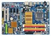
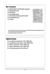
Box Contents GA-EP45-DS3LR or GA-EP45-DS3L motherboard Motherboard driver disk User's Manual Quick Installation Guide One IDE cable and one floppy disk drive cable Two SATA 3Gb/s cables I/O Shield • The box contents above are subject to change without ...
Box Contents GA-EP45-DS3LR or GA-EP45-DS3L motherboard Motherboard driver disk User's Manual Quick Installation Guide One IDE cable and one floppy disk drive cable Two SATA 3Gb/s cables I/O Shield • The box contents above are subject to change without ...
Manual
Page 9
... a certified computer technician. - 9 - If you are connected tightly and securely. • When handling the motherboard, avoid touching any installation steps or have it on top of an antistatic pad or within an electrostatic shielding container. • Before unplugging the power supply cable ... or break motherboard S/N (Serial Number) sticker or warranty sticker provided by unplugging the power cord from the power outlet before installing or removing the motherboard or other hardware components. • When connecting hardware components to the internal connectors on the motherboard, ...
... a certified computer technician. - 9 - If you are connected tightly and securely. • When handling the motherboard, avoid touching any installation steps or have it on top of an antistatic pad or within an electrostatic shielding container. • Before unplugging the power supply cable ... or break motherboard S/N (Serial Number) sticker or warranty sticker provided by unplugging the power cord from the power outlet before installing or removing the motherboard or other hardware components. • When connecting hardware components to the internal connectors on the motherboard, ...

Manual
Page 11
.../System/Power fan speed detection Š CPU overheating warning Š CPU/System/Power fan fail warning Š CPU/System fan speed control (Note 2) - 11 - Hardware Installation
.../System/Power fan speed detection Š CPU overheating warning Š CPU/System/Power fan fail warning Š CPU/System fan speed control (Note 2) - 11 - Hardware Installation
Manual
Page 12
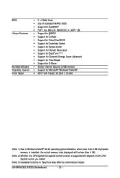
GA-EP45-DS3LR/DS3L Motherboard - 12 - BIOS Unique Features Bundled Software Operating System Form Factor Š 2 x...BIOS Š Support for Q-Flash Š Support for Virtual Dual BIOS Š Support for Download Center Š Support for Xpress Install Š Support for Xpress Recovery2 Š Support for EasyTune (Note 3) Š Support for Dynamic Energy Saver Advanced Š ... 1) Due to Windows Vista/XP 32-bit operating system limitation, when more than 4 GB of physical memory is installed, the actual memory size displayed will be less than 4 GB. (Note 2) Whether the CPU/System fan speed ...
GA-EP45-DS3LR/DS3L Motherboard - 12 - BIOS Unique Features Bundled Software Operating System Form Factor Š 2 x...BIOS Š Support for Q-Flash Š Support for Virtual Dual BIOS Š Support for Download Center Š Support for Xpress Install Š Support for Xpress Recovery2 Š Support for EasyTune (Note 3) Š Support for Dynamic Energy Saver Advanced Š ... 1) Due to Windows Vista/XP 32-bit operating system limitation, when more than 4 GB of physical memory is installed, the actual memory size displayed will be less than 4 GB. (Note 2) Whether the CPU/System fan speed ...
Manual
Page 13
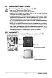
... of the CPU Socket Notch Notch Triangle Pin One Marking on the CPU. Hardware Installation mended that the motherboard supports the CPU. (Go to GIGABYTE's website for the peripherals. If you begin to install the CPU: • Make sure that the system bus frequency be inserted if ... so according to your hardware specifications including the CPU, graphics card, memory, hard drive, etc. 1-3-1 Installing the CPU A. 1-3 Installing the CPU and CPU Cooler Read the following guidelines before installing the CPU to prevent hardware damage. • Locate the pin one of the CPU. It is not...
... of the CPU Socket Notch Notch Triangle Pin One Marking on the CPU. Hardware Installation mended that the motherboard supports the CPU. (Go to GIGABYTE's website for the peripherals. If you begin to install the CPU: • Make sure that the system bus frequency be inserted if ... so according to your hardware specifications including the CPU, graphics card, memory, hard drive, etc. 1-3-1 Installing the CPU A. 1-3 Installing the CPU and CPU Cooler Read the following guidelines before installing the CPU to prevent hardware damage. • Locate the pin one of the CPU. It is not...

Manual
Page 14
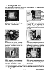
... socket cover from the power outlet to prevent damage to the CPU. GA-EP45-DS3LR/DS3L Motherboard - 14 - B. CPU Socket Lever Step 1: Completely raise the CPU socket lever. Before installing the CPU, make sure to correctly install the CPU into the motherboard CPU socket. Step 5: Once the CPU is... not installed.) Step 4: Hold the CPU with the socket alignment keys) and gently insert the...
... socket cover from the power outlet to prevent damage to the CPU. GA-EP45-DS3LR/DS3L Motherboard - 14 - B. CPU Socket Lever Step 1: Completely raise the CPU socket lever. Before installing the CPU, make sure to correctly install the CPU into the motherboard CPU socket. Step 5: Once the CPU is... not installed.) Step 4: Hold the CPU with the socket alignment keys) and gently insert the...
Manual
Page 15
...extreme care when removing the CPU cooler because the thermal grease/tape between the CPU cooler and CPU may damage the CPU. - 15 - Hardware Installation Inadequately removing the CPU cooler may adhere to the CPU. Step 4: You should hear a "click" when pushing down on the push pins ... is complete. Check that the Male and Female push pins are joined closely. (Refer to your CPU cooler installation manual for instructions on installing the cooler.) Step 5: After the installation, check the back of the CPU cooler to the CPU fan header (CPU_FAN) on the motherboard. Direction of...
...extreme care when removing the CPU cooler because the thermal grease/tape between the CPU cooler and CPU may damage the CPU. - 15 - Hardware Installation Inadequately removing the CPU cooler may adhere to the CPU. Step 4: You should hear a "click" when pushing down on the push pins ... is complete. Check that the Male and Female push pins are joined closely. (Refer to your CPU cooler installation manual for instructions on installing the cooler.) Step 5: After the installation, check the back of the CPU cooler to the CPU fan header (CPU_FAN) on the motherboard. Direction of...
Manual
Page 16
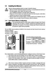
... Dual Channel mode with two or four memory modules, it is installed, the BIOS will double the original memory bandwidth. Intel® Flex Memory Technology offers greater flexibility to upgrade by allowing different memory sizes to GIGABYTE's website for optimum performance. GA-EP45-DS3LR/DS3L Motherboard - 16 - Enabling Dual Channel memory mode will automatically detect...
... Dual Channel mode with two or four memory modules, it is installed, the BIOS will double the original memory bandwidth. Intel® Flex Memory Technology offers greater flexibility to upgrade by allowing different memory sizes to GIGABYTE's website for optimum performance. GA-EP45-DS3LR/DS3L Motherboard - 16 - Enabling Dual Channel memory mode will automatically detect...
Manual
Page 17
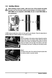
...ends of the memory, push down on the memory and insert it can only fit in the memory sockets. Follow the steps below to install DDR2 DIMMs on the top edge of the memory socket. DDR2 DIMMs are not compatible to DDR DIMMs. Be sure to correctly... install your fingers on this motherboard. Step 2: The clips at both ends of the memory module. Hardware Installation 1-4-2 Installing a Memory Before installing a memory module , make sure to turn off the computer and unplug the power cord from...
...ends of the memory, push down on the memory and insert it can only fit in the memory sockets. Follow the steps below to install DDR2 DIMMs on the top edge of the memory socket. DDR2 DIMMs are not compatible to DDR DIMMs. Be sure to correctly... install your fingers on this motherboard. Step 2: The clips at both ends of the memory module. Hardware Installation 1-4-2 Installing a Memory Before installing a memory module , make sure to turn off the computer and unplug the power cord from...
Manual
Page 18
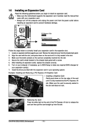
... of the PCI Express x16 slot to prevent hardware damage. GA-EP45-DS3LR/DS3L Motherboard - 18 - 1-5 Installing an Expansion Card Read the following guidelines before installing an expansion card to release the card and then pull the card straight up from the chassis back panel. 2. After installing all expansion cards, replace the chassis cover(s). 6. Turn on...
... of the PCI Express x16 slot to prevent hardware damage. GA-EP45-DS3LR/DS3L Motherboard - 18 - 1-5 Installing an Expansion Card Read the following guidelines before installing an expansion card to release the card and then pull the card straight up from the chassis back panel. 2. After installing all expansion cards, replace the chassis cover(s). 6. Turn on...
Manual
Page 19
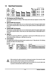
... an external audio system that your audio system provides an optical digital audio in connector. Use this feature, ensure that supports digital optical audio. Hardware Installation Before using this feature, ensure that supports digital coaxial audio. Connection/ Speed LED Activity LED LAN Port Connection/Speed LED: State Description Orange 1 Gbps data...
... an external audio system that your audio system provides an optical digital audio in connector. Use this feature, ensure that supports digital optical audio. Hardware Installation Before using this feature, ensure that supports digital coaxial audio. Connection/ Speed LED Activity LED LAN Port Connection/Speed LED: State Description Orange 1 Gbps data...
Manual
Page 21
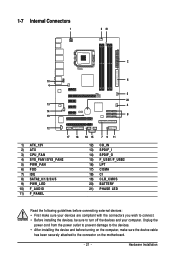
... the power cord from the power outlet to prevent damage to the devices. • After installing the device and before connecting external devices: • First make sure the device cable has been securely attached to turn off the devices and your ... LED Read the following guidelines before turning on the computer, make sure your devices are compliant with the connectors you wish to connect. • Before installing the devices, be sure to the connector on the motherboard. - 21 -
... the power cord from the power outlet to prevent damage to the devices. • After installing the device and before connecting external devices: • First make sure the device cable has been securely attached to turn off the devices and your ... LED Read the following guidelines before turning on the computer, make sure your devices are compliant with the connectors you wish to connect. • Before installing the devices, be sure to the connector on the motherboard. - 21 -
Manual
Page 22
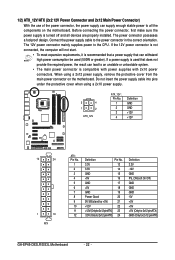
... and 2x12 Main Power Connector) With the use of the power connector, the power supply can supply enough stable power to all devices are properly installed. When using a 2x10 power supply. 3 4 1 2 ATX_12V ATX_12V : Pin No. 1 2 3 4 Definition GND GND +12V +12V 12 24 1 13 ATX ATX: Pin No. 1 2 3 4 5 6 7 8 9 ... -12V GND PS_ON(soft On/Off) GND GND GND -5V +5V +5V +5V (Only for 2x12-pinATX) GND (Only for 2x12-pin ATX) GA-EP45-DS3LR/DS3L Motherboard - 22 - If the 12V power connector is not connected, the computer will not start. • To meet expansion requirements, it is recommended...
... and 2x12 Main Power Connector) With the use of the power connector, the power supply can supply enough stable power to all devices are properly installed. When using a 2x10 power supply. 3 4 1 2 ATX_12V ATX_12V : Pin No. 1 2 3 4 Definition GND GND +12V +12V 12 24 1 13 ATX ATX: Pin No. 1 2 3 4 5 6 7 8 9 ... -12V GND PS_ON(soft On/Off) GND GND GND -5V +5V +5V +5V (Only for 2x12-pinATX) GND (Only for 2x12-pin ATX) GA-EP45-DS3LR/DS3L Motherboard - 22 - If the 12V power connector is not connected, the computer will not start. • To meet expansion requirements, it is recommended...
Manual
Page 23
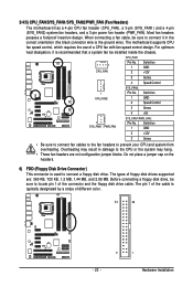
The types of the connector and the floppy disk drive cable. Hardware Installation When connecting a fan cable, be installed inside the chassis. 1 CPU_FAN CPU_FAN: Pin No. 1 2 3 Definition GND +12V Sense 4 Speed Control 1 SYS_FAN2 SYS_FAN2: Pin No. 1 2 3 Definition GND Speed Control Sense 4 +5V 1 SYS_FAN1 / PWR_FAN ...
The types of the connector and the floppy disk drive cable. Hardware Installation When connecting a fan cable, be installed inside the chassis. 1 CPU_FAN CPU_FAN: Pin No. 1 2 3 Definition GND +12V Sense 4 Speed Control 1 SYS_FAN2 SYS_FAN2: Pin No. 1 2 3 Definition GND Speed Control Sense 4 +5V 1 SYS_FAN1 / PWR_FAN ...
Manual
Page 25
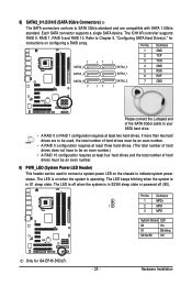
... drives. Pin No. Each SATA connector supports a single SATA device. Refer to Chapter 5, "Configuring SATA Hard Drive(s)," for GA-EP45-DS3LR. - 25 - If more than two hard drives are compatible with SATA 1.5Gb/s standard. Hardware Installation The ICH10R controller supports RAID 0, RAID 1, RAID 5 and RAID 10. Definition 1 GND 2 TXP 7 SATA2_3 SATA2_4 17 1 SATA2_0 SATA2_1...
... drives. Pin No. Each SATA connector supports a single SATA device. Refer to Chapter 5, "Configuring SATA Hard Drive(s)," for GA-EP45-DS3LR. - 25 - If more than two hard drives are compatible with SATA 1.5Gb/s standard. Hardware Installation The ICH10R controller supports RAID 0, RAID 1, RAID 5 and RAID 10. Definition 1 GND 2 TXP 7 SATA2_3 SATA2_4 17 1 SATA2_0 SATA2_1...
Manual
Page 27
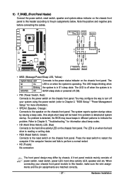
... LED on the chassis front panel. The system reports system startup status by chassis. The LED is on when the hard drive is operating. Hardware Installation Message/Power/ Power Sleep LED Switch Speaker MSG+ MSG- PW+ PWSPEAK+ SPEAK- 2 20 1 19 HD+ HD- RESRES+ NC Hard Drive Activity LED Reset Switch •...
... LED on the chassis front panel. The system reports system startup status by chassis. The LED is on when the hard drive is operating. Hardware Installation Message/Power/ Power Sleep LED Switch Speaker MSG+ MSG- PW+ PWSPEAK+ SPEAK- 2 20 1 19 HD+ HD- RESRES+ NC Hard Drive Activity LED Reset Switch •...
Manual
Page 29
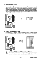
...GND GND No Pin NC • Do not plug the IEEE 1394 bracket (2x5-pin) cable into the USB header. • Prior to installing the USB bracket, be sure to certain expansion cards like graphics cards and sound cards. 14) SPDIF_O (S/PDIF Out Header) This header supports digital ...S/PDIF out and connects a S/PDIF digital audio cable (provided by expansion cards) for your expansion card. Pin No. Hardware Installation Definition 1 SPDIFO 1 2 GND 15) F_USB1/F_USB2 (USB Headers, Yellow) The headers conform to the USB bracket. - 29 - Each USB header can ...
...GND GND No Pin NC • Do not plug the IEEE 1394 bracket (2x5-pin) cable into the USB header. • Prior to installing the USB bracket, be sure to certain expansion cards like graphics cards and sound cards. 14) SPDIF_O (S/PDIF Out Header) This header supports digital ...S/PDIF out and connects a S/PDIF digital audio cable (provided by expansion cards) for your expansion card. Pin No. Hardware Installation Definition 1 SPDIFO 1 2 GND 15) F_USB1/F_USB2 (USB Headers, Yellow) The headers conform to the USB bracket. - 29 - Each USB header can ...


