Manual
Page 1
GA-EP45-DS3LR/ GA-EP45-DS3L LGA775 socket motherboard for Intel® CoreTM processor family/ Intel® Pentium® processor family/Intel® Celeron® processor family User's Manual Rev. 1005 12ME-EP45DS3L-1005R
GA-EP45-DS3LR/ GA-EP45-DS3L LGA775 socket motherboard for Intel® CoreTM processor family/ Intel® Pentium® processor family/Intel® Celeron® processor family User's Manual Rev. 1005 12ME-EP45DS3L-1005R

Manual
Page 2
Motherboard GA-EP45-DS3LR/GA-EP45-DS3L May 23, 2008 Motherboard GA-EP45-DS3LR/ GA-EP45-DS3L May 23, 2008
Motherboard GA-EP45-DS3LR/GA-EP45-DS3L May 23, 2008 Motherboard GA-EP45-DS3LR/ GA-EP45-DS3L May 23, 2008
Manual
Page 3
... exclusively licensed to the specifications and features in this : "REV: X.X." The logo is 1.0. Example: GIGABYTE UNITED INC. is the property of GIGABYTE branded motherboards. For product-related information, check on our website at: http://www.gigabyte.com.tw Identifying Your Motherboard Revision The revision number on how to their respective owners. All rights reserved. Disclaimer...
... exclusively licensed to the specifications and features in this : "REV: X.X." The logo is 1.0. Example: GIGABYTE UNITED INC. is the property of GIGABYTE branded motherboards. For product-related information, check on our website at: http://www.gigabyte.com.tw Identifying Your Motherboard Revision The revision number on how to their respective owners. All rights reserved. Disclaimer...
Manual
Page 4
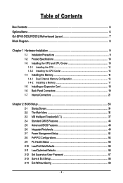
Table of Contents Box Contents ...6 OptionalItems...6 GA-EP45-DS3LR/DS3L Motherboard Layout 7 Block Diagram...8 Chapter 1 Hardware Installation 9 1-1 Installation Precautions 9 1-2 Product Specifications 10 1-3 Installing the CPU and CPU Cooler 13 1-3-1 Installing the CPU 13 1-3-2 Installing the CPU ...
Table of Contents Box Contents ...6 OptionalItems...6 GA-EP45-DS3LR/DS3L Motherboard Layout 7 Block Diagram...8 Chapter 1 Hardware Installation 9 1-1 Installation Precautions 9 1-2 Product Specifications 10 1-3 Installing the CPU and CPU Cooler 13 1-3-1 Installing the CPU 13 1-3-2 Installing the CPU ...
Manual
Page 6
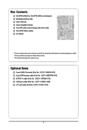
... contents are for reference only. Box Contents GA-EP45-DS3LR or GA-EP45-DS3L motherboard Motherboard driver disk User's Manual Quick Installation Guide One IDE cable and one floppy disk drive cable Two SATA 3Gb/s cables I/O Shield • The box contents above are subject to change without notice. • The motherboard image is for reference only and the...
... contents are for reference only. Box Contents GA-EP45-DS3LR or GA-EP45-DS3L motherboard Motherboard driver disk User's Manual Quick Installation Guide One IDE cable and one floppy disk drive cable Two SATA 3Gb/s cables I/O Shield • The box contents above are subject to change without notice. • The motherboard image is for reference only and the...
Manual
Page 7
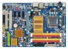
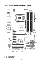
GA-EP45-DS3LR/DS3L Motherboard Layout KB_MS R_SPDIF R_USB_1 R_USB_2 R_USB_3 ATX_12V CPU_FAN PHASE LED ATX LGA775 DDR2_1 GA-EP45-DS3LR/DS3L DDR2_2 DDR2_3 DDR2_4 FDD SYS_FAN2 USB_LAN AUDIO Intel® P45 F_AUDIO SYS_FAN1 RTL8111C PCIEX1_1 PCIEX16 PCIEX1_2 PWR_FAN CODEC SPDIF_O CD_IN IT8718 SPDIF_I PCIEX1_3 PCIEX1_4 B_BIOS M_BIOS BATTERY PCI1 CLR_CMOS PCI2 CI Intel® ICH10R / Intel® ICH10 SATA2_3 SATA2_0 SATA2_4 SATA2_ 1 JMicron 368 IDE SATA2_5 SATA2_2 F_USB1 F_PANEL PWR_LED COMA LPT F_USB2 Only for GA-EP45-DS3L. - 7 - Only for GA-EP45-DS3LR.
GA-EP45-DS3LR/DS3L Motherboard Layout KB_MS R_SPDIF R_USB_1 R_USB_2 R_USB_3 ATX_12V CPU_FAN PHASE LED ATX LGA775 DDR2_1 GA-EP45-DS3LR/DS3L DDR2_2 DDR2_3 DDR2_4 FDD SYS_FAN2 USB_LAN AUDIO Intel® P45 F_AUDIO SYS_FAN1 RTL8111C PCIEX1_1 PCIEX16 PCIEX1_2 PWR_FAN CODEC SPDIF_O CD_IN IT8718 SPDIF_I PCIEX1_3 PCIEX1_4 B_BIOS M_BIOS BATTERY PCI1 CLR_CMOS PCI2 CI Intel® ICH10R / Intel® ICH10 SATA2_3 SATA2_0 SATA2_4 SATA2_ 1 JMicron 368 IDE SATA2_5 SATA2_2 F_USB1 F_PANEL PWR_LED COMA LPT F_USB2 Only for GA-EP45-DS3L. - 7 - Only for GA-EP45-DS3LR.
Manual
Page 9
... validation. • Always remove the AC power by your dealer. If you are connected tightly and securely. • When handling the motherboard, avoid touching any installation steps or have it on top of an antistatic pad or within an electrostatic shielding container. • Before unplugging...the computer system on an uneven surface. • Do not place the computer system in a high-temperature environment. • Turning on the motherboard, make sure they are uncertain about any metal leads or connectors. • It is best to wear an electrostatic discharge (ESD) wrist strap...
... validation. • Always remove the AC power by your dealer. If you are connected tightly and securely. • When handling the motherboard, avoid touching any installation steps or have it on top of an antistatic pad or within an electrostatic shielding container. • Before unplugging...the computer system on an uneven surface. • Do not place the computer system in a high-temperature environment. • Turning on the motherboard, make sure they are uncertain about any metal leads or connectors. • It is best to wear an electrostatic discharge (ESD) wrist strap...

Manual
Page 10
GA-EP45-DS3LR/DS3L Motherboard - 10 - Only for CD In Š 1 x Realtek 8111C chip (10/100/1000 Mbit) &#...to 12 USB 2.0/1.1 ports (8 on the back panel, 4 via the USB brackets connected to the internal USB headers) Only for GA-EP45-DS3LR. Support for SATA RAID 0, RAID 1, RAID 5 and RAID 10 Š JMicron 368 chip: - 1 x IDE ... for DDR2 1333/1200/1066/800/667 MHz memory modules (Go to GIGABYTE's website for the latest memory support list.) Š Realtek ALC888 codec Š High Definition Audio Š 2/4/5.1/7.1-channel Š Support for S/PDIF In/Out Š Support for GA-EP45-DS3L.
GA-EP45-DS3LR/DS3L Motherboard - 10 - Only for CD In Š 1 x Realtek 8111C chip (10/100/1000 Mbit) &#...to 12 USB 2.0/1.1 ports (8 on the back panel, 4 via the USB brackets connected to the internal USB headers) Only for GA-EP45-DS3LR. Support for SATA RAID 0, RAID 1, RAID 5 and RAID 10 Š JMicron 368 chip: - 1 x IDE ... for DDR2 1333/1200/1066/800/667 MHz memory modules (Go to GIGABYTE's website for the latest memory support list.) Š Realtek ALC888 codec Š High Definition Audio Š 2/4/5.1/7.1-channel Š Support for S/PDIF In/Out Š Support for GA-EP45-DS3L.
Manual
Page 12
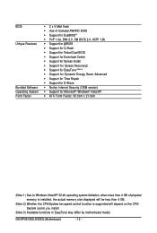
... CPU/System fan speed control function is supported will depend on the CPU/ System cooler you install. (Note 3) Available functions in EasyTune may differ by motherboard model. GA-EP45-DS3LR/DS3L Motherboard - 12 -
... CPU/System fan speed control function is supported will depend on the CPU/ System cooler you install. (Note 3) Available functions in EasyTune may differ by motherboard model. GA-EP45-DS3LR/DS3L Motherboard - 12 -
Manual
Page 13
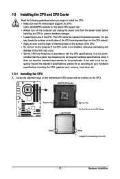
... installing the CPU to your hardware specifications including the CPU, graphics card, memory, hard drive, etc. 1-3-1 Installing the CPU A. mended that the motherboard supports the CPU. (Go to GIGABYTE's website for the peripherals. Hardware Installation The CPU cannot be set the frequency beyond hardware specifications since it does not meet the standard...
... installing the CPU to your hardware specifications including the CPU, graphics card, memory, hard drive, etc. 1-3-1 Installing the CPU A. mended that the motherboard supports the CPU. (Go to GIGABYTE's website for the peripherals. Hardware Installation The CPU cannot be set the frequency beyond hardware specifications since it does not meet the standard...

Manual
Page 14
... with the socket alignment keys) and gently insert the CPU into its locked position. B. CPU Socket Lever Step 1: Completely raise the CPU socket lever. GA-EP45-DS3LR/DS3L Motherboard - 14 - Follow the steps below to turn off the computer and unplug the power cord from the load plate. (To protect the CPU socket, always... the load plate and push the CPU socket lever back into position. Before installing the CPU, make sure to correctly install the CPU into the motherboard CPU socket.
... with the socket alignment keys) and gently insert the CPU into its locked position. B. CPU Socket Lever Step 1: Completely raise the CPU socket lever. GA-EP45-DS3LR/DS3L Motherboard - 14 - Follow the steps below to turn off the computer and unplug the power cord from the load plate. (To protect the CPU socket, always... the load plate and push the CPU socket lever back into position. Before installing the CPU, make sure to correctly install the CPU into the motherboard CPU socket.
Manual
Page 15
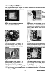
...installing the cooler, note the direction of the arrow sign on the male push pin. (Turning the push pin along the direction of the motherboard. Push down each push pin. Step 6: Finally, attach the power connector of the installed CPU. 1-3-2 Installing the CPU Cooler Follow the ...steps below to correctly install the CPU cooler on the motherboard. (The following procedure uses Intel® boxed cooler as the picture above, the installation is complete. Step 4: You should hear a "click"...
...installing the cooler, note the direction of the arrow sign on the male push pin. (Turning the push pin along the direction of the motherboard. Push down each push pin. Step 6: Finally, attach the power connector of the installed CPU. 1-3-2 Installing the CPU Cooler Follow the ...steps below to correctly install the CPU cooler on the motherboard. (The following procedure uses Intel® boxed cooler as the picture above, the installation is complete. Step 4: You should hear a "click"...
Manual
Page 16
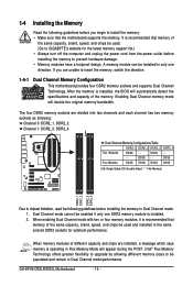
...Technology offers greater flexibility to upgrade by allowing different memory sizes to be used . (Go to GIGABYTE's website for optimum performance. If you begin to install the memory: • Make sure that the motherboard supports the memory. DS/SS - - - - DS/SS - - Dual Channel mode ...are installed, a message which says memory is operating in Dual Channel mode/performance. It is recommended that memory of the memory. GA-EP45-DS3LR/DS3L Motherboard - 16 - When enabling Dual Channel mode with two or four memory modules, it is recommended that memory of different capacity and...
...Technology offers greater flexibility to upgrade by allowing different memory sizes to be used . (Go to GIGABYTE's website for optimum performance. If you begin to install the memory: • Make sure that the motherboard supports the memory. DS/SS - - - - DS/SS - - Dual Channel mode ...are installed, a message which says memory is operating in Dual Channel mode/performance. It is recommended that memory of the memory. GA-EP45-DS3LR/DS3L Motherboard - 16 - When enabling Dual Channel mode with two or four memory modules, it is recommended that memory of different capacity and...
Manual
Page 17
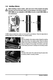
... socket. Hardware Installation Spread the retaining clips at both ends of the socket will snap into the memory socket. Place the memory module on this motherboard. Step 1: Note the orientation of the memory, push down on the memory and insert it can only fit in the picture on the top edge...
... socket. Hardware Installation Spread the retaining clips at both ends of the socket will snap into the memory socket. Place the memory module on this motherboard. Step 1: Note the orientation of the memory, push down on the memory and insert it can only fit in the picture on the top edge...
Manual
Page 18
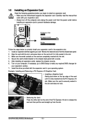
... on the card until it is securely seated in the slot. 3. Secure the card's metal bracket to install an expansion card: • Make sure the motherboard supports the expansion card. PCI Express x1 Slot PCI Express x16 Slot PCI Slot Follow the steps below to release the card and then pull.... • Always turn off the computer and unplug the power cord from the chassis back panel. 2. Carefully read the manual that supports your operating system. GA-EP45-DS3LR/DS3L Motherboard - 18 -
... on the card until it is securely seated in the slot. 3. Secure the card's metal bracket to install an expansion card: • Make sure the motherboard supports the expansion card. PCI Express x1 Slot PCI Express x16 Slot PCI Slot Follow the steps below to release the card and then pull.... • Always turn off the computer and unplug the power cord from the chassis back panel. 2. Carefully read the manual that supports your operating system. GA-EP45-DS3LR/DS3L Motherboard - 18 -
Manual
Page 19
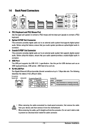
... Ethernet LAN port provides Internet connection at up to a back panel connector, first remove the cable from your device and then remove it from the motherboard. • When removing the cable, pull it side to side to connect a PS/2 keyboard. Connection/ Speed LED Activity LED LAN Port Connection/Speed LED: State...
... Ethernet LAN port provides Internet connection at up to a back panel connector, first remove the cable from your device and then remove it from the motherboard. • When removing the cable, pull it side to side to connect a PS/2 keyboard. Connection/ Speed LED Activity LED LAN Port Connection/Speed LED: State...
Manual
Page 20
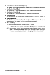
... out jack. Only microphones still MUST be reconfigured to connect center/subwoofer speakers in a 5.1/7.1-channel audio configuration. Side Speaker Out Jack (Gray) Use this jack. GA-EP45-DS3LR/DS3L Motherboard - 20 - Rear Speaker Out Jack (Black) Use this audio jack for line in jack. Mic In Jack (Pink) The default Mic in a 4/5.1/7.1-channel audio...
... out jack. Only microphones still MUST be reconfigured to connect center/subwoofer speakers in a 5.1/7.1-channel audio configuration. Side Speaker Out Jack (Gray) Use this jack. GA-EP45-DS3LR/DS3L Motherboard - 20 - Rear Speaker Out Jack (Black) Use this audio jack for line in jack. Mic In Jack (Pink) The default Mic in a 4/5.1/7.1-channel audio...
Manual
Page 21
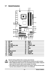
...) SPDIF_O 15) F_USB1/F_USB2 16) LPT 17) COMA 18) CI 19) CLR_CMOS 20) BATTERY 21) PHASE LED Read the following guidelines before turning on the motherboard. - 21 -
...) SPDIF_O 15) F_USB1/F_USB2 16) LPT 17) COMA 18) CI 19) CLR_CMOS 20) BATTERY 21) PHASE LED Read the following guidelines before turning on the motherboard. - 21 -
Manual
Page 22
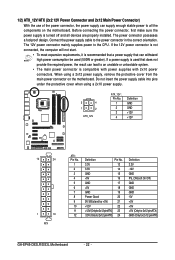
...power supply cable into pins under the protective cover when using a 2x12 power supply, remove the protective cover from the main power connector on the motherboard. The 12V power connector mainly supplies power to an unstable or unbootable system. • The main power connector is used (500W or greater)....3V -12V GND PS_ON(soft On/Off) GND GND GND -5V +5V +5V +5V (Only for 2x12-pinATX) GND (Only for 2x12-pin ATX) GA-EP45-DS3LR/DS3L Motherboard - 22 - If the 12V power connector is not connected, the computer will not start. • To meet expansion requirements, it is turned off and...
...power supply cable into pins under the protective cover when using a 2x12 power supply, remove the protective cover from the main power connector on the motherboard. The 12V power connector mainly supplies power to an unstable or unbootable system. • The main power connector is used (500W or greater)....3V -12V GND PS_ON(soft On/Off) GND GND GND -5V +5V +5V +5V (Only for 2x12-pinATX) GND (Only for 2x12-pin ATX) GA-EP45-DS3LR/DS3L Motherboard - 22 - If the 12V power connector is not connected, the computer will not start. • To meet expansion requirements, it is turned off and...
Manual
Page 23
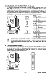
... used to connect it is the ground wire). Before connecting a floppy disk drive, be sure to connect a floppy disk drive. The motherboard supports CPU fan speed control, which requires the use of floppy disk drives supported are not configuration jumper blocks. The pin 1 of the... connector and the floppy disk drive cable. The types of a CPU fan with fan speed control design. 3/4/5) CPU_FAN/SYS_FAN1/SYS_FAN2/PWR_FAN (Fan Headers) The motherboard has a 4-pin CPU fan header (CPU_FAN), a 3-pin (SYS_FAN1) and a 4-pin (SYS_FAN2) system fan headers, and a 3-pin power fan header (PWR_FAN...
... used to connect it is the ground wire). Before connecting a floppy disk drive, be sure to connect a floppy disk drive. The motherboard supports CPU fan speed control, which requires the use of floppy disk drives supported are not configuration jumper blocks. The pin 1 of the... connector and the floppy disk drive cable. The types of a CPU fan with fan speed control design. 3/4/5) CPU_FAN/SYS_FAN1/SYS_FAN2/PWR_FAN (Fan Headers) The motherboard has a 4-pin CPU fan header (CPU_FAN), a 3-pin (SYS_FAN1) and a 4-pin (SYS_FAN2) system fan headers, and a 3-pin power fan header (PWR_FAN...


