
Manual
Page 4
..." will install all of the autorun screen and you use the Smart TPM utility, ensure that are recommended to the Install New Utilities menu. Some motherboard driver disks include the Smart TPM utility in "Xpress Install." Click the "Install All" button on the right of the selected drivers, including the Infineon... and list all of Smart TPM to install the Infineon TPM driver and the Smart TPM utility altogether. - 4 - Installing the Infineon TPM Driver Insert the GIGABYTE motherboard driver disk.
..." will install all of the autorun screen and you use the Smart TPM utility, ensure that are recommended to the Install New Utilities menu. Some motherboard driver disks include the Smart TPM utility in "Xpress Install." Click the "Install All" button on the right of the selected drivers, including the Infineon... and list all of Smart TPM to install the Infineon TPM driver and the Smart TPM utility altogether. - 4 - Installing the Infineon TPM Driver Insert the GIGABYTE motherboard driver disk.

Manual
Page 7
... former. 2. Upon completing the steps above, click OK to that you plug in the system BIOS. Before creating a Bluetooth cell phone key, make sure your motherboard includes a Bluetooth receiver and turn on the search and Bluetooth functions on the left will store the encrypted TPM User Password in .
... former. 2. Upon completing the steps above, click OK to that you plug in the system BIOS. Before creating a Bluetooth cell phone key, make sure your motherboard includes a Bluetooth receiver and turn on the search and Bluetooth functions on the left will store the encrypted TPM User Password in .

Manual
Page 19
... by plugging in BIOS Setup and then set earlier and click OK to complete creating the USB key. Do not turn off or reset your motherboard includes a Bluetooth receiver and turn on the search and Bluetooth functions on the Configure USB Storages tab. To cancel a USB key: To cancel a USB key...
... by plugging in BIOS Setup and then set earlier and click OK to complete creating the USB key. Do not turn off or reset your motherboard includes a Bluetooth receiver and turn on the search and Bluetooth functions on the Configure USB Storages tab. To cancel a USB key: To cancel a USB key...
Manual
Page 3
... the Infineon TPM driver and the GIGABYTE Ultra TPM utility have been installed in your system and list all of the Infineon TPM Driver and GIGABYTE Ultra TPM items. Install the Infineon TPM driver. Method 1: Insert the GIGABYTE motherboard driver disk. "Xpress Install" will... automatically scan your system. Installing the Infineon TPM Driver and the GIGABYTE Ultra TPM Utility To use GIGABYTE's Ultra TPM, ensure that...
... the Infineon TPM driver and the GIGABYTE Ultra TPM utility have been installed in your system and list all of the Infineon TPM Driver and GIGABYTE Ultra TPM items. Install the Infineon TPM driver. Method 1: Insert the GIGABYTE motherboard driver disk. "Xpress Install" will... automatically scan your system. Installing the Infineon TPM Driver and the GIGABYTE Ultra TPM Utility To use GIGABYTE's Ultra TPM, ensure that...
Manual
Page 1
GA-EP45-DQ6 LGA775 socket motherboard for Intel® CoreTM processor family/ Intel® Pentium® processor family/Intel® Celeron® processor family User's Manual Rev. 1004 12ME-EP45DQ6-1004R
GA-EP45-DQ6 LGA775 socket motherboard for Intel® CoreTM processor family/ Intel® Pentium® processor family/Intel® Celeron® processor family User's Manual Rev. 1004 12ME-EP45DQ6-1004R

Manual
Page 2
Motherboard GA-EP45-DQ6 May 15, 2008 Motherboard GA-EP45-DQ6 May 15, 2008
Motherboard GA-EP45-DQ6 May 15, 2008 Motherboard GA-EP45-DQ6 May 15, 2008
Manual
Page 3
...transmitted, or published in this manual are legally registered to assist in this : "REV: X.X." No part of GIGABYTE branded motherboards. Check your motherboard looks like this manual is exclusively licensed to use of this manual may be made by GIGA-BYTE TECHNOLOGY CO.,... LTD as the exclu- GIGABYTE UNITED INC. Disclaimer Information in the use GIGABYTE's unique features, read the User's Manual. „ For instructions on your motherboard revision before updating motherboard BIOS, drivers, or when looking for technical information. ...
...transmitted, or published in this manual are legally registered to assist in this : "REV: X.X." No part of GIGABYTE branded motherboards. Check your motherboard looks like this manual is exclusively licensed to use of this manual may be made by GIGA-BYTE TECHNOLOGY CO.,... LTD as the exclu- GIGABYTE UNITED INC. Disclaimer Information in the use GIGABYTE's unique features, read the User's Manual. „ For instructions on your motherboard revision before updating motherboard BIOS, drivers, or when looking for technical information. ...
Manual
Page 4
Table of Contents Box Contents ...6 OptionalItems ...6 GA-EP45-DQ6 Motherboard Layout 7 Block Diagram ...8 Chapter 1 Hardware Installation 9 1-1 Installation Precautions 9 1-2 Product Specifications 10 1-3 Installing the CPU and CPU Cooler 13 1-3-1 Installing the CPU 13 1-3-2 Installing the CPU ...
Table of Contents Box Contents ...6 OptionalItems ...6 GA-EP45-DQ6 Motherboard Layout 7 Block Diagram ...8 Chapter 1 Hardware Installation 9 1-1 Installation Precautions 9 1-2 Product Specifications 10 1-3 Installing the CPU and CPU Cooler 13 1-3-1 Installing the CPU 13 1-3-2 Installing the CPU ...
Manual
Page 6
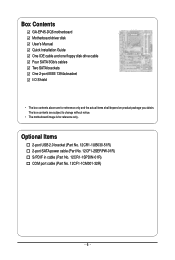
... S/PDIF in cable (Part No. 12CR1-1SPDIN-01R) COM port cable (Part No. 12CF1-1CM001-32R) - 6 - The box contents are for reference only. Box Contents GA-EP45-DQ6 motherboard Motherboard driver disk User's Manual Quick Installation Guide One IDE cable and one floppy disk drive cable Four SATA 3Gb/s cables Two SATA brackets One 2-port... IEEE 1394a bracket I/O Shield • The box contents above are subject to change without notice. • The motherboard image is for reference only and the actual items shall depend on product package you obtain.
... S/PDIF in cable (Part No. 12CR1-1SPDIN-01R) COM port cable (Part No. 12CF1-1CM001-32R) - 6 - The box contents are for reference only. Box Contents GA-EP45-DQ6 motherboard Motherboard driver disk User's Manual Quick Installation Guide One IDE cable and one floppy disk drive cable Four SATA 3Gb/s cables Two SATA brackets One 2-port... IEEE 1394a bracket I/O Shield • The box contents above are subject to change without notice. • The motherboard image is for reference only and the actual items shall depend on product package you obtain.
Manual
Page 7
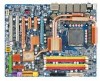
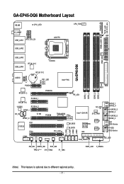
GA-EP45-DQ6 Motherboard Layout PHASE LED ACPI_LED (S0/1/3/4/5_LED) KB_MS CPU_LED CPU_FAN R_SPDIF ATX LGA775 USB_LAN1 ATX_12V_2X DIMM_LED USB_LAN2 PWR_FAN USB_LAN3 GA-EP45-DQ6 USB_LAN4 RTL8111C AUDIO RTL8111C BAT F_AUDIO PCIEX1 PE1_LED ...GD1 GD2 RTL8111C PCIEX16 PCIEX4_1 Intel® P45 PE_LED DDR2_1 DDR2_2 DDR2_3 DDR2_4 MD2 MD1 FDD RTL8111C CODEC PCIEX4_2 SPDIF_I CD_IN CI SPDIF_O PCI1 IT8720 PCI2 SA_LED PCIEX8 TSB43AB23 Intel® ICH10R SYS_FAN1 PCI_LED M_BIOS B_BIOS GIGABYTE...
GA-EP45-DQ6 Motherboard Layout PHASE LED ACPI_LED (S0/1/3/4/5_LED) KB_MS CPU_LED CPU_FAN R_SPDIF ATX LGA775 USB_LAN1 ATX_12V_2X DIMM_LED USB_LAN2 PWR_FAN USB_LAN3 GA-EP45-DQ6 USB_LAN4 RTL8111C AUDIO RTL8111C BAT F_AUDIO PCIEX1 PE1_LED ...GD1 GD2 RTL8111C PCIEX16 PCIEX4_1 Intel® P45 PE_LED DDR2_1 DDR2_2 DDR2_3 DDR2_4 MD2 MD1 FDD RTL8111C CODEC PCIEX4_2 SPDIF_I CD_IN CI SPDIF_O PCI1 IT8720 PCI2 SA_LED PCIEX8 TSB43AB23 Intel® ICH10R SYS_FAN1 PCI_LED M_BIOS B_BIOS GIGABYTE...
Manual
Page 9
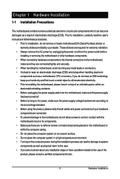
...shielding container. • Before unplugging the power supply cable from the power outlet before installing or removing the motherboard or other hardware components. • When connecting hardware components to the internal connectors on the computer power during... best to wear an electrostatic discharge (ESD) wrist strap when handling electronic components such as a motherboard, CPU or memory. Chapter 1 Hardware Installation 1-1 Installation Precautions The motherboard contains numerous delicate electronic circuits and components which can lead to damage to system components as well ...
...shielding container. • Before unplugging the power supply cable from the power outlet before installing or removing the motherboard or other hardware components. • When connecting hardware components to the internal connectors on the computer power during... best to wear an electrostatic discharge (ESD) wrist strap when handling electronic components such as a motherboard, CPU or memory. Chapter 1 Hardware Installation 1-1 Installation Precautions The motherboard contains numerous delicate electronic circuits and components which can lead to damage to system components as well ...
Manual
Page 10
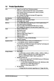
... memory (Note 1) Š Dual channel memory architecture Š Support for DDR2 1200/1066/800/667 MHz memory modules (Go to GIGABYTE's website for the latest memory support list.) Š Realtek ALC889A codec Š High Definition Audio Š 2/4/5.1/7.1-channel Š Support... 6 x SATA 3Gb/s connectors (SATA2_0, SATA2_1, SATA2_2, SATA2_3, SATA2_4, SATA2_5) supporting up to 1 floppy disk drive GA-EP45-DQ6 Motherboard - 10 - Support for SATA RAID 0, RAID 1, RAID 5 and RAID 10 Š GIGABYTE SATA2 chip: - 1 x IDE connector supporting ATA-133/100/66/33 and up to 2 IDE devices Š 2 ...
... memory (Note 1) Š Dual channel memory architecture Š Support for DDR2 1200/1066/800/667 MHz memory modules (Go to GIGABYTE's website for the latest memory support list.) Š Realtek ALC889A codec Š High Definition Audio Š 2/4/5.1/7.1-channel Š Support... 6 x SATA 3Gb/s connectors (SATA2_0, SATA2_1, SATA2_2, SATA2_3, SATA2_4, SATA2_5) supporting up to 1 floppy disk drive GA-EP45-DQ6 Motherboard - 10 - Support for SATA RAID 0, RAID 1, RAID 5 and RAID 10 Š GIGABYTE SATA2 chip: - 1 x IDE connector supporting ATA-133/100/66/33 and up to 2 IDE devices Š 2 ...
Manual
Page 12
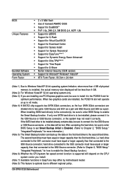
... Initial to Enabled. (Refer to Chapter 2, "BIOS Setup," "Integrated Peripherals," for more than 4 GB of physical memory is supported will be lost. GA-EP45-DQ6 Motherboard - 12 - The second hard drive must have equal or larger capacity than that connected to two pairs: GS0-Source and GS1 as a pair and ... for optimum performance. If the SATA hard drive to be installed already contains data, be sure to connect it in EasyTune may differ by motherboard model. (Note 8) This feature is to be sure to the second hard drive. hard drive connected to the GS3 connector must have equal...
... Initial to Enabled. (Refer to Chapter 2, "BIOS Setup," "Integrated Peripherals," for more than 4 GB of physical memory is supported will be lost. GA-EP45-DQ6 Motherboard - 12 - The second hard drive must have equal or larger capacity than that connected to two pairs: GS0-Source and GS1 as a pair and ... for optimum performance. If the SATA hard drive to be installed already contains data, be sure to connect it in EasyTune may differ by motherboard model. (Note 8) This feature is to be sure to the second hard drive. hard drive connected to the GS3 connector must have equal...
Manual
Page 13
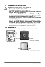
It is not installed, otherwise overheating and damage of the CPU. mended that the motherboard supports the CPU. (Go to GIGABYTE's website for the peripherals. LGA775 CPU Socket Alignment Key LGA 775 CPU Alignment Key Pin One Corner of the CPU Socket Notch Notch... to your hardware specifications including the CPU, graphics card, memory, hard drive, etc. 1-3-1 Installing the CPU A. Locate the alignment keys on the motherboard CPU socket and the notches on the CPU - 13 - The CPU cannot be set the frequency beyond hardware specifications since it does not meet the...
It is not installed, otherwise overheating and damage of the CPU. mended that the motherboard supports the CPU. (Go to GIGABYTE's website for the peripherals. LGA775 CPU Socket Alignment Key LGA 775 CPU Alignment Key Pin One Corner of the CPU Socket Notch Notch... to your hardware specifications including the CPU, graphics card, memory, hard drive, etc. 1-3-1 Installing the CPU A. Locate the alignment keys on the motherboard CPU socket and the notches on the CPU - 13 - The CPU cannot be set the frequency beyond hardware specifications since it does not meet the...
Manual
Page 14
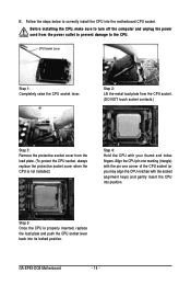
... from the power outlet to prevent damage to the CPU. Before installing the CPU, make sure to correctly install the CPU into its locked position. GA-EP45-DQ6 Motherboard - 14 - Align the CPU pin one marking (triangle) with the pin one corner of the CPU socket (or you may align the CPU notches with..., always replace the protective socket cover when the CPU is properly inserted, replace the load plate and push the CPU socket lever back into the motherboard CPU socket. B.
... from the power outlet to prevent damage to the CPU. Before installing the CPU, make sure to correctly install the CPU into its locked position. GA-EP45-DQ6 Motherboard - 14 - Align the CPU pin one marking (triangle) with the pin one corner of the CPU socket (or you may align the CPU notches with..., always replace the protective socket cover when the CPU is properly inserted, replace the load plate and push the CPU socket lever back into the motherboard CPU socket. B.
Manual
Page 15
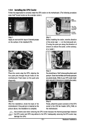
...and CPU may damage the CPU. - 15 - 1-3-2 Installing the CPU Cooler Follow the steps below to correctly install the CPU cooler on the motherboard. (The following procedure uses Intel® boxed cooler as the picture above, the installation is to install.) Step 3: Place the cooler atop the... pin. Check that the Male and Female push pins are joined closely. (Refer to the CPU fan header (CPU_FAN) on the surface of the motherboard. Hardware Installation Step 4: You should hear a "click" when pushing down on installing the cooler.) Step 5: After the installation, check the back ...
...and CPU may damage the CPU. - 15 - 1-3-2 Installing the CPU Cooler Follow the steps below to correctly install the CPU cooler on the motherboard. (The following procedure uses Intel® boxed cooler as the picture above, the installation is to install.) Step 3: Place the cooler atop the... pin. Check that the Male and Female push pins are joined closely. (Refer to the CPU fan header (CPU_FAN) on the surface of the motherboard. Hardware Installation Step 4: You should hear a "click" when pushing down on installing the cooler.) Step 5: After the installation, check the back ...
Manual
Page 16
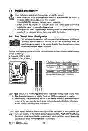
...Read the following guidelines before you are unable to insert the memory, switch the direction. 1-4-1 Dual Channel Memory Configuration This motherboard provides four DDR2 memory sockets and supports Dual Channel Technology. After the memory is operating in only one DDR2 memory module ... Memory modules have a foolproof design. GA-EP45-DQ6 Motherboard - 16 - A memory module can be enabled if only one direction. DS/SS - - It is recommended that memory of the same capacity, brand, speed, and chips be used . (Go to GIGABYTE's website for optimum performance. If you ...
...Read the following guidelines before you are unable to insert the memory, switch the direction. 1-4-1 Dual Channel Memory Configuration This motherboard provides four DDR2 memory sockets and supports Dual Channel Technology. After the memory is operating in only one DDR2 memory module ... Memory modules have a foolproof design. GA-EP45-DQ6 Motherboard - 16 - A memory module can be enabled if only one direction. DS/SS - - It is recommended that memory of the same capacity, brand, speed, and chips be used . (Go to GIGABYTE's website for optimum performance. If you ...
Manual
Page 17
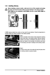
... memory and insert it can only fit in the memory sockets. Follow the steps below to the memory module. Place the memory module on this motherboard. As indicated in the picture on the left, place your memory modules in one direction. Notch DDR2 DIMM A DDR2 memory module has a notch, so it...
... memory and insert it can only fit in the memory sockets. Follow the steps below to the memory module. Place the memory module on this motherboard. As indicated in the picture on the left, place your memory modules in one direction. Notch DDR2 DIMM A DDR2 memory module has a notch, so it...
Manual
Page 18
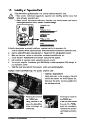
... card in your expansion card in the expansion slot. 1. Secure the card's metal bracket to install an expansion card: • Make sure the motherboard supports the expansion card. Install the driver provided with your card. Example: Installing and Removing a PCI Express Graphics Card: • Installing a Graphics...; Removing the Card from the PCIEX16 slot: Gently push back on the lever on the card are completely inserted into the PCI Express slot. GA-EP45-DQ6 Motherboard - 18 - • Removing the Card from the PCIEX8 slot: Press the white latch at the end of the card until it is...
... card in your expansion card in the expansion slot. 1. Secure the card's metal bracket to install an expansion card: • Make sure the motherboard supports the expansion card. Install the driver provided with your card. Example: Installing and Removing a PCI Express Graphics Card: • Installing a Graphics...; Removing the Card from the PCIEX16 slot: Gently push back on the lever on the card are completely inserted into the PCI Express slot. GA-EP45-DQ6 Motherboard - 18 - • Removing the Card from the PCIEX8 slot: Press the white latch at the end of the card until it is...
Manual
Page 19
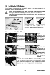
... SATA signal cable and SATA power cable securely into to the power supply. Before connecting the SATA signal cable, make sure to turn off your motherboard. Hardware Installation the external SATA con- Then attach the SATA power cable to the power connector on the bracket. For SATA device in external enclosure...
... SATA signal cable and SATA power cable securely into to the power supply. Before connecting the SATA signal cable, make sure to turn off your motherboard. Hardware Installation the external SATA con- Then attach the SATA power cable to the power connector on the bracket. For SATA device in external enclosure...


