
Manual
Page 4
... Install" will automatically scan your system and list all of Smart TPM to install the Infineon TPM driver and the Smart TPM utility altogether. - 4 - Some motherboard driver disks include the Smart TPM utility in "Xpress Install." Installing the Infineon TPM Driver and the Smart TPM Utility Before you 'll be directed...
... Install" will automatically scan your system and list all of Smart TPM to install the Infineon TPM driver and the Smart TPM utility altogether. - 4 - Some motherboard driver disks include the Smart TPM utility in "Xpress Install." Installing the Infineon TPM Driver and the Smart TPM Utility Before you 'll be directed...

Manual
Page 7
... with your cell phone for the Bluetooth enabled cell phone(s). Step 3: Create Your Smart TPM Key 1. Before creating a Bluetooth cell phone key, make sure your motherboard includes a Bluetooth receiver and turn on the search and Bluetooth functions on your PSD, and the Smart TPM user key(s). - 7 - You can select more than...
... with your cell phone for the Bluetooth enabled cell phone(s). Step 3: Create Your Smart TPM Key 1. Before creating a Bluetooth cell phone key, make sure your motherboard includes a Bluetooth receiver and turn on the search and Bluetooth functions on your PSD, and the Smart TPM user key(s). - 7 - You can select more than...

Manual
Page 19
...'t display your Bluetooth-enabled cell phone, click Refresh to let Smart TPM re-detect the device.) Before creating a Bluetooth cell phone key, make sure your motherboard includes a Bluetooth receiver and turn off or reset your PSD by plugging in BIOS Setup and then set earlier and click OK to "Enabled/Activate...
...'t display your Bluetooth-enabled cell phone, click Refresh to let Smart TPM re-detect the device.) Before creating a Bluetooth cell phone key, make sure your motherboard includes a Bluetooth receiver and turn off or reset your PSD by plugging in BIOS Setup and then set earlier and click OK to "Enabled/Activate...
Manual
Page 3
... drivers that are recommended for installation. Method 1: Insert the GIGABYTE motherboard driver disk. "Xpress Install" will automatically scan your system. 2. Installing the Infineon TPM Driver and the GIGABYTE Ultra TPM Utility To use GIGABYTE's Ultra TPM, ensure that the Infineon TPM driver and the GIGABYTE Ultra TPM utility have been installed in your system and...
... drivers that are recommended for installation. Method 1: Insert the GIGABYTE motherboard driver disk. "Xpress Install" will automatically scan your system. 2. Installing the Infineon TPM Driver and the GIGABYTE Ultra TPM Utility To use GIGABYTE's Ultra TPM, ensure that the Infineon TPM driver and the GIGABYTE Ultra TPM utility have been installed in your system and...
Manual
Page 1
GA-EP45-DQ6 LGA775 socket motherboard for Intel® CoreTM processor family/ Intel® Pentium® processor family/Intel® Celeron® processor family User's Manual Rev. 1004 12ME-EP45DQ6-1004R
GA-EP45-DQ6 LGA775 socket motherboard for Intel® CoreTM processor family/ Intel® Pentium® processor family/Intel® Celeron® processor family User's Manual Rev. 1004 12ME-EP45DQ6-1004R

Manual
Page 2
Motherboard GA-EP45-DQ6 May 15, 2008 Motherboard GA-EP45-DQ6 May 15, 2008
Motherboard GA-EP45-DQ6 May 15, 2008 Motherboard GA-EP45-DQ6 May 15, 2008
Manual
Page 3
...the product. „ For detailed product information, carefully read or download the information on/from the Support\Motherboard\Technology Guide page on how to GIGABYTE UNITED INC. Example: Changes to their respective owners. Disclaimer Information in this manual is protected by GIGA-...BYTE TECHNOLOGY CO., LTD as the exclu- Check your motherboard looks like this product, GIGABYTE provides the following types of documentations: „ For quick set-up of this manual may be reproduced, copied, ...
...the product. „ For detailed product information, carefully read or download the information on/from the Support\Motherboard\Technology Guide page on how to GIGABYTE UNITED INC. Example: Changes to their respective owners. Disclaimer Information in this manual is protected by GIGA-...BYTE TECHNOLOGY CO., LTD as the exclu- Check your motherboard looks like this product, GIGABYTE provides the following types of documentations: „ For quick set-up of this manual may be reproduced, copied, ...
Manual
Page 4
Table of Contents Box Contents ...6 OptionalItems ...6 GA-EP45-DQ6 Motherboard Layout 7 Block Diagram ...8 Chapter 1 Hardware Installation 9 1-1 Installation Precautions 9 1-2 Product Specifications 10 1-3 Installing the CPU and CPU Cooler 13 1-3-1 Installing the CPU 13 1-3-2 Installing the CPU ...
Table of Contents Box Contents ...6 OptionalItems ...6 GA-EP45-DQ6 Motherboard Layout 7 Block Diagram ...8 Chapter 1 Hardware Installation 9 1-1 Installation Precautions 9 1-2 Product Specifications 10 1-3 Installing the CPU and CPU Cooler 13 1-3-1 Installing the CPU 13 1-3-2 Installing the CPU ...
Manual
Page 6
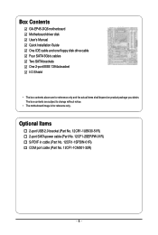
... S/PDIF in cable (Part No. 12CR1-1SPDIN-01R) COM port cable (Part No. 12CF1-1CM001-32R) - 6 - The box contents are for reference only. Box Contents GA-EP45-DQ6 motherboard Motherboard driver disk User's Manual Quick Installation Guide One IDE cable and one floppy disk drive cable Four SATA 3Gb/s cables Two SATA brackets One 2-port... IEEE 1394a bracket I/O Shield • The box contents above are subject to change without notice. • The motherboard image is for reference only and the actual items shall depend on product package you obtain.
... S/PDIF in cable (Part No. 12CR1-1SPDIN-01R) COM port cable (Part No. 12CF1-1CM001-32R) - 6 - The box contents are for reference only. Box Contents GA-EP45-DQ6 motherboard Motherboard driver disk User's Manual Quick Installation Guide One IDE cable and one floppy disk drive cable Four SATA 3Gb/s cables Two SATA brackets One 2-port... IEEE 1394a bracket I/O Shield • The box contents above are subject to change without notice. • The motherboard image is for reference only and the actual items shall depend on product package you obtain.
Manual
Page 7
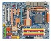
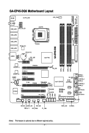
GA-EP45-DQ6 Motherboard Layout PHASE LED ACPI_LED (S0/1/3/4/5_LED) KB_MS CPU_LED CPU_FAN R_SPDIF ATX LGA775 USB_LAN1 ATX_12V_2X DIMM_LED USB_LAN2 PWR_FAN USB_LAN3 GA-EP45-DQ6 USB_LAN4 RTL8111C AUDIO RTL8111C BAT F_AUDIO PCIEX1 PE1_LED ...GD1 GD2 RTL8111C PCIEX16 PCIEX4_1 Intel® P45 PE_LED DDR2_1 DDR2_2 DDR2_3 DDR2_4 MD2 MD1 FDD RTL8111C CODEC PCIEX4_2 SPDIF_I CD_IN CI SPDIF_O PCI1 IT8720 PCI2 SA_LED PCIEX8 TSB43AB23 Intel® ICH10R SYS_FAN1 PCI_LED M_BIOS B_BIOS GIGABYTE...
GA-EP45-DQ6 Motherboard Layout PHASE LED ACPI_LED (S0/1/3/4/5_LED) KB_MS CPU_LED CPU_FAN R_SPDIF ATX LGA775 USB_LAN1 ATX_12V_2X DIMM_LED USB_LAN2 PWR_FAN USB_LAN3 GA-EP45-DQ6 USB_LAN4 RTL8111C AUDIO RTL8111C BAT F_AUDIO PCIEX1 PE1_LED ...GD1 GD2 RTL8111C PCIEX16 PCIEX4_1 Intel® P45 PE_LED DDR2_1 DDR2_2 DDR2_3 DDR2_4 MD2 MD1 FDD RTL8111C CODEC PCIEX4_2 SPDIF_I CD_IN CI SPDIF_O PCI1 IT8720 PCI2 SA_LED PCIEX8 TSB43AB23 Intel® ICH10R SYS_FAN1 PCI_LED M_BIOS B_BIOS GIGABYTE...
Manual
Page 9
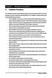
... wrist strap, keep your hands dry and first touch a metal object to eliminate static electricity. • Prior to installing the motherboard, please have a problem related to the use of electrostatic discharge (ESD). These stickers are required for warranty validation. • ... within an electrostatic shielding container. • Before unplugging the power supply cable from the power outlet before installing or removing the motherboard or other hardware components. • When connecting hardware components to wear an electrostatic discharge (ESD) wrist strap when handling electronic...
... wrist strap, keep your hands dry and first touch a metal object to eliminate static electricity. • Prior to installing the motherboard, please have a problem related to the use of electrostatic discharge (ESD). These stickers are required for warranty validation. • ... within an electrostatic shielding container. • Before unplugging the power supply cable from the power outlet before installing or removing the motherboard or other hardware components. • When connecting hardware components to wear an electrostatic discharge (ESD) wrist strap when handling electronic...
Manual
Page 10
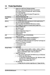
... 5 and RAID 10 Š GIGABYTE SATA2 chip: - 1 x IDE connector supporting ATA-133/100/66/33 and up to 2 IDE devices Š 2 x SiI5723 chips (Smart Backup): - 4 x SATA 3Gb/s connectors (GS0-Source, GS1, GS2-Source, GS3) supporting up to 1 floppy disk drive GA-EP45-DQ6 Motherboard - 10 - Support for Smart ...system memory (Note 1) Š Dual channel memory architecture Š Support for DDR2 1200/1066/800/667 MHz memory modules (Go to GIGABYTE's website for the latest memory support list.) Š Realtek ALC889A codec Š High Definition Audio Š 2/4/5.1/7.1-channel Š Support ...
... 5 and RAID 10 Š GIGABYTE SATA2 chip: - 1 x IDE connector supporting ATA-133/100/66/33 and up to 2 IDE devices Š 2 x SiI5723 chips (Smart Backup): - 4 x SATA 3Gb/s connectors (GS0-Source, GS1, GS2-Source, GS3) supporting up to 1 floppy disk drive GA-EP45-DQ6 Motherboard - 10 - Support for Smart ...system memory (Note 1) Š Dual channel memory architecture Š Support for DDR2 1200/1066/800/667 MHz memory modules (Go to GIGABYTE's website for the latest memory support list.) Š Realtek ALC889A codec Š High Definition Audio Š 2/4/5.1/7.1-channel Š Support ...
Manual
Page 12
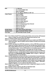
...(s), be installed, please connect it to the GS0-Source or GS2-Source connector, or the system may not read it in EasyTune may differ by motherboard model. (Note 8) This feature is optional due to different regional policy. The second hard drive must have equal or larger capacity than that connected to... for Time Repair Š Support for Q-Share Š Norton Internet Security (OEM version) Š Support for more than that connected to the GS0-Source connector; GA-EP45-DQ6 Motherboard - 12 -
...(s), be installed, please connect it to the GS0-Source or GS2-Source connector, or the system may not read it in EasyTune may differ by motherboard model. (Note 8) This feature is optional due to different regional policy. The second hard drive must have equal or larger capacity than that connected to... for Time Repair Š Support for Q-Share Š Norton Internet Security (OEM version) Š Support for more than that connected to the GS0-Source connector; GA-EP45-DQ6 Motherboard - 12 -
Manual
Page 13
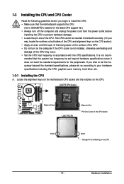
... the standard specifications, please do so according to prevent hardware damage. • Locate the pin one of the CPU. mended that the motherboard supports the CPU. (Go to GIGABYTE's website for the peripherals. Hardware Installation 1-3 Installing the CPU and CPU Cooler Read the following guidelines before installing the CPU to your hardware...
... the standard specifications, please do so according to prevent hardware damage. • Locate the pin one of the CPU. mended that the motherboard supports the CPU. (Go to GIGABYTE's website for the peripherals. Hardware Installation 1-3 Installing the CPU and CPU Cooler Read the following guidelines before installing the CPU to your hardware...
Manual
Page 14
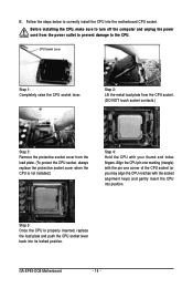
.... (DO NOT touch socket contacts.) Step 3: Remove the protective socket cover from the power outlet to prevent damage to correctly install the CPU into position. GA-EP45-DQ6 Motherboard - 14 - Follow the steps below to the CPU. CPU Socket Lever Step 1: Completely raise the CPU socket lever. Align the CPU pin one marking (triangle... index fingers. Step 5: Once the CPU is not installed.) Step 4: Hold the CPU with the socket alignment keys) and gently insert the CPU into the motherboard CPU socket.
.... (DO NOT touch socket contacts.) Step 3: Remove the protective socket cover from the power outlet to prevent damage to correctly install the CPU into position. GA-EP45-DQ6 Motherboard - 14 - Follow the steps below to the CPU. CPU Socket Lever Step 1: Completely raise the CPU socket lever. Align the CPU pin one marking (triangle... index fingers. Step 5: Once the CPU is not installed.) Step 4: Hold the CPU with the socket alignment keys) and gently insert the CPU into the motherboard CPU socket.
Manual
Page 15
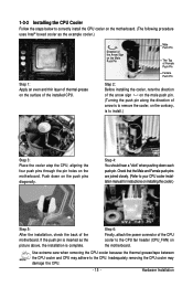
... 1: Apply an even and thin layer of thermal grease on the surface of the CPU cooler to the CPU fan header (CPU_FAN) on the motherboard. Step 6: Finally, attach the power connector of the installed CPU. Inadequately removing the CPU cooler may adhere to remove the cooler, on the ...contrary, is complete. 1-3-2 Installing the CPU Cooler Follow the steps below to correctly install the CPU cooler on the motherboard. (The following procedure uses Intel® boxed cooler as the picture above, the installation is to install.) Step 3: Place the cooler atop the ...
... 1: Apply an even and thin layer of thermal grease on the surface of the CPU cooler to the CPU fan header (CPU_FAN) on the motherboard. Step 6: Finally, attach the power connector of the installed CPU. Inadequately removing the CPU cooler may adhere to remove the cooler, on the ...contrary, is complete. 1-3-2 Installing the CPU Cooler Follow the steps below to correctly install the CPU cooler on the motherboard. (The following procedure uses Intel® boxed cooler as the picture above, the installation is to install.) Step 3: Place the cooler atop the ...
Manual
Page 16
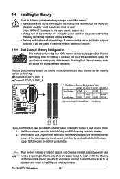
...support list.) • Always turn off the computer and unplug the power cord from the power outlet before installing the memory to GIGABYTE's website for optimum performance. DS/SS - - When memory modules of the memory. Dual Channel mode cannot be installed in ... memory modules, it is installed. 2. 1-4 Installing the Memory Read the following guidelines before installing the memory in Dual Channel mode. 1. GA-EP45-DQ6 Motherboard - 16 - After the memory is operating in Flex Memory Mode will double the original memory bandwidth. The four DDR2 memory sockets are ...
...support list.) • Always turn off the computer and unplug the power cord from the power outlet before installing the memory to GIGABYTE's website for optimum performance. DS/SS - - When memory modules of the memory. Dual Channel mode cannot be installed in ... memory modules, it is installed. 2. 1-4 Installing the Memory Read the following guidelines before installing the memory in Dual Channel mode. 1. GA-EP45-DQ6 Motherboard - 16 - After the memory is operating in Flex Memory Mode will double the original memory bandwidth. The four DDR2 memory sockets are ...
Manual
Page 17
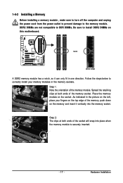
... socket will snap into the memory socket. Step 2: The clips at both ends of the memory module. Hardware Installation Place the memory module on this motherboard. 1-4-2 Installing a Memory Before installing a memory module , make sure to turn off the computer and unplug the power cord from the power outlet to prevent damage...
... socket will snap into the memory socket. Step 2: The clips at both ends of the memory module. Hardware Installation Place the memory module on this motherboard. 1-4-2 Installing a Memory Before installing a memory module , make sure to turn off the computer and unplug the power cord from the power outlet to prevent damage...
Manual
Page 18
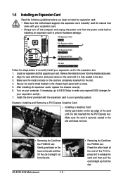
...is fully inserted into the slot. 4. Align the card with a screw. 5. Make sure the card is fully seated in your computer. GA-EP45-DQ6 Motherboard - 18 - • Removing the Card from the power outlet before you begin to prevent hardware damage. Turn on the card are ...Installing an Expansion Card Read the following guidelines before installing an expansion card to install an expansion card: • Make sure the motherboard supports the expansion card. Make sure the metal contacts on your operating system. Locate an expansion slot that came with the expansion...
...is fully inserted into the slot. 4. Align the card with a screw. 5. Make sure the card is fully seated in your computer. GA-EP45-DQ6 Motherboard - 18 - • Removing the Card from the power outlet before you begin to prevent hardware damage. Turn on the card are ...Installing an Expansion Card Read the following guidelines before installing an expansion card to install an expansion card: • Make sure the motherboard supports the expansion card. Make sure the metal contacts on your operating system. Locate an expansion slot that came with the expansion...
Manual
Page 19
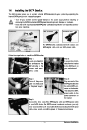
... the power connector on the bracket. Then attach the SATA power cable to the chassis back panel with a screw. Follow the steps below to your motherboard.
... the power connector on the bracket. Then attach the SATA power cable to the chassis back panel with a screw. Follow the steps below to your motherboard.


