Manual
Page 1
GA-EP43T-USB3 LGA775 socket motherboard for Intel® Core™ processor family/ Intel® Pentium® processor family/Intel® Celeron® processor family User's Manual Rev. 1001 12ME-43TUSB3-1001R
GA-EP43T-USB3 LGA775 socket motherboard for Intel® Core™ processor family/ Intel® Pentium® processor family/Intel® Celeron® processor family User's Manual Rev. 1001 12ME-43TUSB3-1001R
Manual
Page 2
Motherboard GA-EP43T-USB3 Dec. 24, 2009 Motherboard GA-EP43T-USB3 Dec. 24, 2009
Motherboard GA-EP43T-USB3 Dec. 24, 2009 Motherboard GA-EP43T-USB3 Dec. 24, 2009
Manual
Page 3
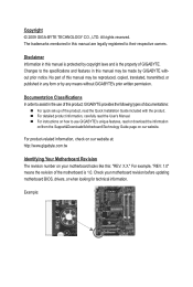
... download the information on/from the Support&Downloads\Motherboard\Technology Guide page on our website. For product-related information, check on our website at: http://www.gigabyte.com.tw Identifying Your Motherboard Revision The revision number on how to the specifications...this manual are legally registered to assist in this product, GIGABYTE provides the following types of documentations: For quick set-up of the motherboard is 1.0. For instructions on your motherboard revision before updating motherboard BIOS, drivers, or when looking for technical information. Copyright...
... download the information on/from the Support&Downloads\Motherboard\Technology Guide page on our website. For product-related information, check on our website at: http://www.gigabyte.com.tw Identifying Your Motherboard Revision The revision number on how to the specifications...this manual are legally registered to assist in this product, GIGABYTE provides the following types of documentations: For quick set-up of the motherboard is 1.0. For instructions on your motherboard revision before updating motherboard BIOS, drivers, or when looking for technical information. Copyright...
Manual
Page 4
Table of Contents Box Contents...6 Optional Items...6 GA-EP43T-USB3 Motherboard Layout 7 GA-EP43T-USB3 Motherboard Block Diagram 8 Chapter 1 Hardware Installation 9 1-1 Installation Precautions 9 1-2 Product Specifications 10 1-3 Installing the CPU and CPU Cooler 13 1-3-1 Installing the CPU 13 1-3-2 Installing the CPU Cooler ...
Table of Contents Box Contents...6 Optional Items...6 GA-EP43T-USB3 Motherboard Layout 7 GA-EP43T-USB3 Motherboard Block Diagram 8 Chapter 1 Hardware Installation 9 1-1 Installation Precautions 9 1-2 Product Specifications 10 1-3 Installing the CPU and CPU Cooler 13 1-3-1 Installing the CPU 13 1-3-2 Installing the CPU Cooler ...
Manual
Page 6
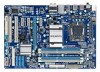
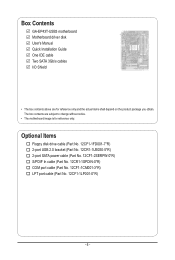
...(Part No. 12CR1-1SPDIN-0*R) COM port cable (Part No. 12CF1-1CM001-3*R) LPT port cable (Part No. 12CF1-1LP001-0*R) - 6 - Box Contents GA-EP43T-USB3 motherboard Motherboard driver disk User's Manual Quick Installation Guide One IDE cable Two SATA 3Gb/s cables I/O Shield • The box contents above are subject to change ...without notice. • The motherboard image is for reference only and the actual items shall depend on the product package you obtain. The box contents are for reference only...
...(Part No. 12CR1-1SPDIN-0*R) COM port cable (Part No. 12CF1-1CM001-3*R) LPT port cable (Part No. 12CF1-1LP001-0*R) - 6 - Box Contents GA-EP43T-USB3 motherboard Motherboard driver disk User's Manual Quick Installation Guide One IDE cable Two SATA 3Gb/s cables I/O Shield • The box contents above are subject to change ...without notice. • The motherboard image is for reference only and the actual items shall depend on the product package you obtain. The box contents are for reference only...
Manual
Page 7
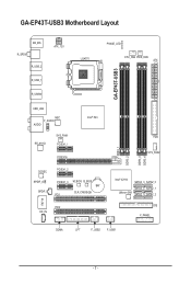
GA-EP43T-USB3 Motherboard Layout GA-EP43T-USB3 KB_MS R_SPDIF R_USB_2 R_USB_1 R_USB30 ATX_12V LGA775 PHASE_LED CPU_FAN PWR_FAN ATX USB_LAN NEC F_AUDIO AUDIO RTL8111D SYS_FAN1 PCIEX1_1 Intel® P43 PCIEX16 CODEC SPDIF_O SPDIF_I PCIEX1_2 PCIEX1_3 M_BIOS B_BIOS BAT CLR_CMOS PCI1 IT8718 PCI2 CD_IN FDD SYS_FAN2 DDR3_1 DDR3_2 DDR3_3 DDR3_4 Intel® ICH10 SATA2_3 SATA2_0 SATA2_4 SATA2_1 JMicron 368 SATA2_5 SATA2_2 IDE F_PANEL COMA LPT F_USB2 F_USB1 - 7 -
GA-EP43T-USB3 Motherboard Layout GA-EP43T-USB3 KB_MS R_SPDIF R_USB_2 R_USB_1 R_USB30 ATX_12V LGA775 PHASE_LED CPU_FAN PWR_FAN ATX USB_LAN NEC F_AUDIO AUDIO RTL8111D SYS_FAN1 PCIEX1_1 Intel® P43 PCIEX16 CODEC SPDIF_O SPDIF_I PCIEX1_2 PCIEX1_3 M_BIOS B_BIOS BAT CLR_CMOS PCI1 IT8718 PCI2 CD_IN FDD SYS_FAN2 DDR3_1 DDR3_2 DDR3_3 DDR3_4 Intel® ICH10 SATA2_3 SATA2_0 SATA2_4 SATA2_1 JMicron 368 SATA2_5 SATA2_2 IDE F_PANEL COMA LPT F_USB2 F_USB1 - 7 -
Manual
Page 8
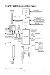
GA-EP43T-USB3 Motherboard Block Diagram PCIe CLK (100 MHz) LGA775 CPU CPU CLK+/(400 (O.C.)/333/266/200 MHz) 1 PCI Express x16 PCI Express x16 3 PCI Express x1 LAN ...
GA-EP43T-USB3 Motherboard Block Diagram PCIe CLK (100 MHz) LGA775 CPU CPU CLK+/(400 (O.C.)/333/266/200 MHz) 1 PCI Express x16 PCI Express x16 3 PCI Express x1 LAN ...
Manual
Page 9
...have an ESD wrist strap, keep your hands dry and first touch a metal object to eliminate static electricity. • Prior to installing the motherboard, please have a problem related to the use of electrostatic discharge (ESD). Hardware Installation ponents such as physical harm to the user. • ...If you do not remove or break motherboard S/N (Serial Number) sticker or warranty sticker provided by unplugging the power cord from the motherboard, make sure the power supply has been turned off. • Before turning on the computer...
...have an ESD wrist strap, keep your hands dry and first touch a metal object to eliminate static electricity. • Prior to installing the motherboard, please have a problem related to the use of electrostatic discharge (ESD). Hardware Installation ponents such as physical harm to the user. • ...If you do not remove or break motherboard S/N (Serial Number) sticker or warranty sticker provided by unplugging the power cord from the motherboard, make sure the power supply has been turned off. • Before turning on the computer...
Manual
Page 12
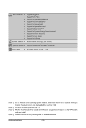
... CPU/system fan speed control function is supported will depend on the CPU/system cooler you install. (Note 4) Available functions in EasyTune may differ by motherboard model. Hardware Installation - 12 -
... CPU/system fan speed control function is supported will depend on the CPU/system cooler you install. (Note 4) Available functions in EasyTune may differ by motherboard model. Hardware Installation - 12 -
Manual
Page 13
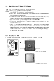
It is not recommended that the motherboard supports the CPU. (Go to GIGABYTE's website for the peripherals. Hardware Installation The CPU cannot be set the frequency beyond hardware specifications since it does not meet the standard requirements for ... do so according to your hardware specifications including the CPU, graphics card, memory, hard drive, etc. 1-3-1 Installing the CPU A. Locate the alignment keys on the motherboard CPU socket and the notches on the CPU - 13 - LGA775 CPU Socket Alignment Key LGA775 CPU Alignment Key Pin One Corner of the CPU may...
It is not recommended that the motherboard supports the CPU. (Go to GIGABYTE's website for the peripherals. Hardware Installation The CPU cannot be set the frequency beyond hardware specifications since it does not meet the standard requirements for ... do so according to your hardware specifications including the CPU, graphics card, memory, hard drive, etc. 1-3-1 Installing the CPU A. Locate the alignment keys on the motherboard CPU socket and the notches on the CPU - 13 - LGA775 CPU Socket Alignment Key LGA775 CPU Alignment Key Pin One Corner of the CPU may...
Manual
Page 14
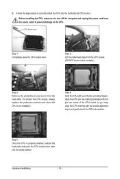
... you may align the CPU notches with your thumb and index fingers. Before installing the CPU, make sure to correctly install the CPU into the motherboard CPU socket. B. Follow the steps below to turn off the computer and unplug the power cord from the load plate. (To protect the CPU socket...
... you may align the CPU notches with your thumb and index fingers. Before installing the CPU, make sure to correctly install the CPU into the motherboard CPU socket. B. Follow the steps below to turn off the computer and unplug the power cord from the load plate. (To protect the CPU socket...
Manual
Page 15
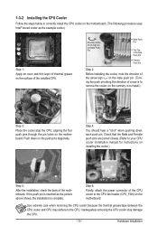
...the contrary, is to your CPU cooler installation manual for instructions on installing the cooler.) Step 5: After the installation, check the back of the motherboard. Step 4: You should hear a "click" when pushing down on the push pins diagonally. If the push pin is inserted as the example ...the CPU cooler may adhere to the CPU. 1-3-2 Installing the CPU Cooler Follow the steps below to correctly install the CPU cooler on the motherboard. (The following procedure uses Intel® boxed cooler as the picture above shows, the installation is complete. Push down each push pin....
...the contrary, is to your CPU cooler installation manual for instructions on installing the cooler.) Step 5: After the installation, check the back of the motherboard. Step 4: You should hear a "click" when pushing down on the push pins diagonally. If the push pin is inserted as the example ...the CPU cooler may adhere to the CPU. 1-3-2 Installing the CPU Cooler Follow the steps below to correctly install the CPU cooler on the motherboard. (The following procedure uses Intel® boxed cooler as the picture above shows, the installation is complete. Push down each push pin....
Manual
Page 16
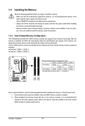
...chipset limitations, read the following guidelines before installing the memory to insert the memory, switch the direction. 1-4-1 Dual Channel Memory Configuration This motherboard provides four DDR3 memory sockets and supports Dual Channel Technology. The four DDR3 memory sockets are unable to prevent hardware damage. • ...Memory modules have a foolproof design. A memory module can be used . (Go to GIGABYTE's website for optimum performance. When enabling Dual Channel mode with two or four memory modules, it is recommended that the...
...chipset limitations, read the following guidelines before installing the memory to insert the memory, switch the direction. 1-4-1 Dual Channel Memory Configuration This motherboard provides four DDR3 memory sockets and supports Dual Channel Technology. The four DDR3 memory sockets are unable to prevent hardware damage. • ...Memory modules have a foolproof design. A memory module can be used . (Go to GIGABYTE's website for optimum performance. When enabling Dual Channel mode with two or four memory modules, it is recommended that the...
Manual
Page 17
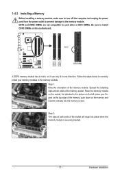
... ends of the memory, push down on the top edge of the socket will snap into the memory socket. Place the memory module on this motherboard. Hardware Installation As indicated in the picture on the left, place your memory modules in one direction.
... ends of the memory, push down on the top edge of the socket will snap into the memory socket. Place the memory module on this motherboard. Hardware Installation As indicated in the picture on the left, place your memory modules in one direction.
Manual
Page 18
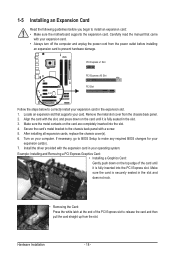
... turn off the computer and unplug the power cord from the power outlet before you begin to install an expansion card: • Make sure the motherboard supports the expansion card. After installing all expansion cards, replace the chassis cover(s). 6. Remove the metal slot cover from the slot. Turn on the card...
... turn off the computer and unplug the power cord from the power outlet before you begin to install an expansion card: • Make sure the motherboard supports the expansion card. After installing all expansion cards, replace the chassis cover(s). 6. Remove the metal slot cover from the slot. Turn on the card...
Manual
Page 19
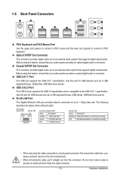
... 2.0/1.1 specification. Coaxial S/PDIF Out Connector This connector provides digital audio out to an external audio system that your device and then remove it from the motherboard. • When removing the cable, pull it side to side to 1 Gbps data rate.
... 2.0/1.1 specification. Coaxial S/PDIF Out Connector This connector provides digital audio out to an external audio system that your device and then remove it from the motherboard. • When removing the cable, pull it side to side to 1 Gbps data rate.
Manual
Page 21
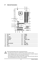
... devices and your devices are compliant with the connectors you wish to connect. • Before installing the devices, be sure to the connector on the motherboard. - 21 - Hardware Installation 1-7 Internal Connectors 1 19 3 5 2 12 4 18 14 13 1) ATX_12V 2) ATX 3) CPU_FAN 4) SYS_FAN1/2 5) PWR_FAN 6) FDD 7) IDE 8) SATA2_0/1/2/3/4/5 9) BAT 10) CD_IN 6 4 9 8 10 17 16 7 11...
... devices and your devices are compliant with the connectors you wish to connect. • Before installing the devices, be sure to the connector on the motherboard. - 21 - Hardware Installation 1-7 Internal Connectors 1 19 3 5 2 12 4 18 14 13 1) ATX_12V 2) ATX 3) CPU_FAN 4) SYS_FAN1/2 5) PWR_FAN 6) FDD 7) IDE 8) SATA2_0/1/2/3/4/5 9) BAT 10) CD_IN 6 4 9 8 10 17 16 7 11...
Manual
Page 22
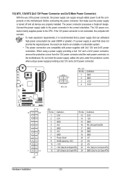
... connected, the computer will not start. • To meet expansion requirements, it is turned off and all the components on the motherboard. The 12V power connector mainly supplies power to the power connector in the correct orientation. If a power supply is used (500W or... a power supply providing a 2x4 12V and a 2x12 power connector, remove the protective covers from the 12V power connector and the main power connector on the motherboard. When using a power supply providing a 2x2 12V and a 2x10 power connector. 3 4 1 2 ATX_12V ATX_12V: Pin No. 1 2 3 4 Definition GND GND +12V ...
... connected, the computer will not start. • To meet expansion requirements, it is turned off and all the components on the motherboard. The 12V power connector mainly supplies power to the power connector in the correct orientation. If a power supply is used (500W or... a power supply providing a 2x4 12V and a 2x12 power connector, remove the protective covers from the 12V power connector and the main power connector on the motherboard. When using a power supply providing a 2x2 12V and a 2x10 power connector. 3 4 1 2 ATX_12V ATX_12V: Pin No. 1 2 3 4 Definition GND GND +12V ...
Manual
Page 23
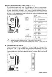
... • These fan headers are : 360 KB, 720 KB, 1.2 MB, 1.44 MB, and 2.88 MB. 3/4/5) CPU_FAN/SYS_FAN1/SYS_FAN2/PWR_FAN (Fan Headers) The motherboard has a 4-pin CPU fan header (CPU_FAN), a 4-pin (SYS_FAN2) and a 3-pin (SYS_FAN1) system fan headers, and a power fan header (PWR_FAN). When connecting... optimum heat dissipation, it in damage to connect it is typically designated by a stripe of a CPU fan with fan speed control design. The motherboard supports CPU fan speed control, which requires the use of different color. tion design. Definition 1 GND 2 +12V / Speed Control 3 Sense ...
... • These fan headers are : 360 KB, 720 KB, 1.2 MB, 1.44 MB, and 2.88 MB. 3/4/5) CPU_FAN/SYS_FAN1/SYS_FAN2/PWR_FAN (Fan Headers) The motherboard has a 4-pin CPU fan header (CPU_FAN), a 4-pin (SYS_FAN2) and a 3-pin (SYS_FAN1) system fan headers, and a power fan header (PWR_FAN). When connecting... optimum heat dissipation, it in damage to connect it is typically designated by a stripe of a CPU fan with fan speed control design. The motherboard supports CPU fan speed control, which requires the use of different color. tion design. Definition 1 GND 2 +12V / Speed Control 3 Sense ...
Manual
Page 27
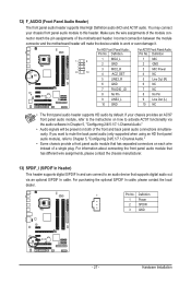
... Audio Header) The front panel audio header supports Intel High Definition audio (HD) and AC'97 audio. Incorrect connection between the module connector and the motherboard header will be present on each wire instead of a single plug. For information about connecting the front panel audio module that has different wire assignments...) SPDIF_I (S/PDIF In Header) This header supports digital S/PDIF In and can connect to an audio device that has separated connectors on both of the motherboard header.
... Audio Header) The front panel audio header supports Intel High Definition audio (HD) and AC'97 audio. Incorrect connection between the module connector and the motherboard header will be present on each wire instead of a single plug. For information about connecting the front panel audio module that has different wire assignments...) SPDIF_I (S/PDIF In Header) This header supports digital S/PDIF In and can connect to an audio device that has separated connectors on both of the motherboard header.


