Manual
Page 3
... or by GIGABYTE without GIGABYTE's prior written permission. All rights reserved. No part of this manual may be made by any means without prior notice. For detailed product information, carefully read or download the information on/from the Support&Downloads\Motherboard\Technology Guide page on your motherboard revision before updating motherboard BIOS, drivers, or when looking for technical information. Copyright © 2009 GIGA-BYTE TECHNOLOGY CO., LTD...
... or by GIGABYTE without GIGABYTE's prior written permission. All rights reserved. No part of this manual may be made by any means without prior notice. For detailed product information, carefully read or download the information on/from the Support&Downloads\Motherboard\Technology Guide page on your motherboard revision before updating motherboard BIOS, drivers, or when looking for technical information. Copyright © 2009 GIGA-BYTE TECHNOLOGY CO., LTD...
Manual
Page 4
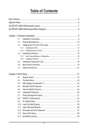
... Box Contents...6 Optional Items...6 GA-EP43T-USB3 Motherboard Layout 7 GA-EP43T-USB3 Motherboard Block Diagram 8 Chapter 1 Hardware Installation 9 1-1 Installation Precautions 9 1-2 Product Specifications 10 1-3 Installing the CPU and CPU Cooler 13 1-3-1 Installing the CPU 13 1-3-2 Installing the CPU Cooler 15 1-4 Installing the Memory 16 1-4-1 Dual Channel Memory Configuration 16 1-4-2 Installing a Memory 17 1-5 Installing an Expansion Card 18 1-6 Back Panel Connectors 19 1-7 Internal Connectors 21 Chapter 2 BIOS Setup 31 2-1 Startup Screen 32 2-2 The Main Menu 33 2-3 MB...
... Box Contents...6 Optional Items...6 GA-EP43T-USB3 Motherboard Layout 7 GA-EP43T-USB3 Motherboard Block Diagram 8 Chapter 1 Hardware Installation 9 1-1 Installation Precautions 9 1-2 Product Specifications 10 1-3 Installing the CPU and CPU Cooler 13 1-3-1 Installing the CPU 13 1-3-2 Installing the CPU Cooler 15 1-4 Installing the Memory 16 1-4-1 Dual Channel Memory Configuration 16 1-4-2 Installing a Memory 17 1-5 Installing an Expansion Card 18 1-6 Back Panel Connectors 19 1-7 Internal Connectors 21 Chapter 2 BIOS Setup 31 2-1 Startup Screen 32 2-2 The Main Menu 33 2-3 MB...

Manual
Page 11
...connector 1 x 4-pin ATX 12V power connector 1 x floppy disk drive connector 1 x IDE connector 6 x SATA 3Gb/s connectors 1 x CPU fan header 2 x system fan headers 1 x power fan header 1 x front panel header 1 x front panel audio header 1 x CD In connector 1 x S/PDIF Out header 1 x S/PDIF In header 2 x USB 2.0/1.1 headers 1 x serial port header 1 x parallel port header 1 x clearing CMOS jumper 1 x PS/2 keyboard port 1 x PS/2 mouse port 1 x coaxial S/PDIF Out connector 1 x optical S/PDIF Out connector 8 x USB 2.0/1.1 ports 2 x USB 3.0 ports 1 x RJ-45 port 6 x audio jacks (Center/Subwoofer Speaker...
...connector 1 x 4-pin ATX 12V power connector 1 x floppy disk drive connector 1 x IDE connector 6 x SATA 3Gb/s connectors 1 x CPU fan header 2 x system fan headers 1 x power fan header 1 x front panel header 1 x front panel audio header 1 x CD In connector 1 x S/PDIF Out header 1 x S/PDIF In header 2 x USB 2.0/1.1 headers 1 x serial port header 1 x parallel port header 1 x clearing CMOS jumper 1 x PS/2 keyboard port 1 x PS/2 mouse port 1 x coaxial S/PDIF Out connector 1 x optical S/PDIF Out connector 8 x USB 2.0/1.1 ports 2 x USB 3.0 ports 1 x RJ-45 port 6 x audio jacks (Center/Subwoofer Speaker...
Manual
Page 16
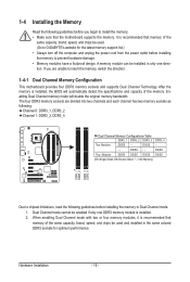
... the memory, switch the direction. 1-4-1 Dual Channel Memory Configuration This motherboard provides four DDR3 memory sockets and supports Dual Channel Technology. The four DDR3 memory sockets are unable to install the memory: • Make sure that the motherboard supports the memory. When enabling Dual Channel mode with two or four memory modules, it is installed, the BIOS will double the original memory bandwidth. DS/SS - - - - 1-4 Installing the Memory Read the following : Channel 0: DDR3_1, DDR3_2 Channel 1: DDR3_3, DDR3_4 Dual Channel Memory Configurations Table DDR3_1...
... the memory, switch the direction. 1-4-1 Dual Channel Memory Configuration This motherboard provides four DDR3 memory sockets and supports Dual Channel Technology. The four DDR3 memory sockets are unable to install the memory: • Make sure that the motherboard supports the memory. When enabling Dual Channel mode with two or four memory modules, it is installed, the BIOS will double the original memory bandwidth. DS/SS - - - - 1-4 Installing the Memory Read the following : Channel 0: DDR3_1, DDR3_2 Channel 1: DDR3_3, DDR3_4 Dual Channel Memory Configurations Table DDR3_1...
Manual
Page 18
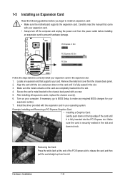
... card is fully inserted into the slot. 4. Hardware Installation - 18 - Install the driver provided with a screw. 5. Align the card with your expansion card. • Always turn off the computer and unplug the power cord from the chassis back panel. 2. If necessary, go to BIOS Setup to install an expansion card: • Make sure the motherboard supports the expansion card. Turn on the card are completely inserted into the PCI Express slot. Locate an expansion slot...
... card is fully inserted into the slot. 4. Hardware Installation - 18 - Install the driver provided with a screw. 5. Align the card with your expansion card. • Always turn off the computer and unplug the power cord from the chassis back panel. 2. If necessary, go to BIOS Setup to install an expansion card: • Make sure the motherboard supports the expansion card. Turn on the card are completely inserted into the PCI Express slot. Locate an expansion slot...
Manual
Page 23
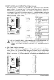
... on the headers. 6) FDD (Floppy Disk Drive Connector) This connector is the ground wire). The pin 1 of the cable is recommended that a system fan be installed inside the chassis. When connecting a fan cable, be sure to prevent your CPU and system from overheating. CPU_FAN: Pin No. Definition 1 GND 2 +12V 3 Sense • Be sure to connect fan cables to the fan headers to locate pin 1 of floppy disk drives supported are not configuration jumper blocks. Before connecting a floppy disk drive, be sure to connect a floppy disk drive. For optimum...
... on the headers. 6) FDD (Floppy Disk Drive Connector) This connector is the ground wire). The pin 1 of the cable is recommended that a system fan be installed inside the chassis. When connecting a fan cable, be sure to prevent your CPU and system from overheating. CPU_FAN: Pin No. Definition 1 GND 2 +12V 3 Sense • Be sure to connect fan cables to the fan headers to locate pin 1 of floppy disk drives supported are not configuration jumper blocks. Before connecting a floppy disk drive, be sure to connect a floppy disk drive. For optimum...
Manual
Page 30
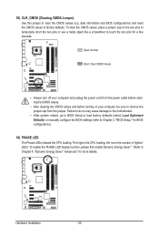
... number of lighted LEDs. 18) CLR_CMOS (Clearing CMOS Jumper) Use this jumper to factory defaults. Hardware Installation - 30 - date information and BIOS configurations) and reset the CMOS values to clear the CMOS values (e.g. The higher the CPU loading, the more details. To clear the CMOS values, place a jumper cap on your computer and unplug the power cord from the jumper. To enable the PHASE LED display function, please first enable Dynamic Energy Saver™ . Failure to do...
... number of lighted LEDs. 18) CLR_CMOS (Clearing CMOS Jumper) Use this jumper to factory defaults. Hardware Installation - 30 - date information and BIOS configurations) and reset the CMOS values to clear the CMOS values (e.g. The higher the CPU loading, the more details. To clear the CMOS values, place a jumper cap on your computer and unplug the power cord from the jumper. To enable the PHASE LED display function, please first enable Dynamic Energy Saver™ . Failure to do...
Manual
Page 31
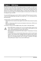
... a beep code during the POST. If this occurs, try to clear the CMOS values and reset the board to default values. (Refer to the "Load Optimized Defaults" section in this chapter or introductions of the battery/ clearing CMOS jumper in the main menu of the BIOS Setup program. BIOS Setup To access the BIOS Setup program, press the key during system startup, saving system parameters and loading operating system, etc. To upgrade the BIOS, use either the GIGABYTE Q-Flash or @BIOS utility...
... a beep code during the POST. If this occurs, try to clear the CMOS values and reset the board to default values. (Refer to the "Load Optimized Defaults" section in this chapter or introductions of the battery/ clearing CMOS jumper in the main menu of the BIOS Setup program. BIOS Setup To access the BIOS Setup program, press the key during system startup, saving system parameters and loading operating system, etc. To upgrade the BIOS, use either the GIGABYTE Q-Flash or @BIOS utility...
Manual
Page 32
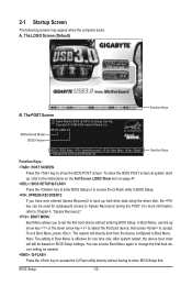
... first boot device, then press to access the Q-Flash utility directly without entering BIOS Setup. The system will still be used for one time only. BIOS Setup - 32 - The POST Screen Award Modular BIOS v6.00PG, An Energy Star Ally Copyright (C) 1984-2009, Award Software, Inc. In Boot Menu, use the up hard drive data using the driver disk, the key can access Boot Menu again to change the first boot device setting as needed. : Q-FLASH Press the key to accept. 2-1 Startup Screen The following screens may...
... first boot device, then press to access the Q-Flash utility directly without entering BIOS Setup. The system will still be used for one time only. BIOS Setup - 32 - The POST Screen Award Modular BIOS v6.00PG, An Energy Star Ally Copyright (C) 1984-2009, Award Software, Inc. In Boot Menu, use the up hard drive data using the driver disk, the key can access Boot Menu again to change the first boot device setting as needed. : Q-FLASH Press the key to accept. 2-1 Startup Screen The following screens may...

Manual
Page 34
... IDE, SATA, USB, integrated audio, and integrated LAN, etc. Power Management Setup Use this menu to a profile. It allows you to save the current BIOS settings to configure all changes and the previous settings remain in BIOS Setup. Set User Password Change, set , or disable password. It allows you can also carry out this function to load the BIOS settings from BIOS If your CPU, memory, etc. Standard CMOS Features Use this menu to configure the system time and date, hard drive types, floppy disk drive types...
... IDE, SATA, USB, integrated audio, and integrated LAN, etc. Power Management Setup Use this menu to a profile. It allows you to save the current BIOS settings to configure all changes and the previous settings remain in BIOS Setup. Set User Password Change, set , or disable password. It allows you can also carry out this function to load the BIOS settings from BIOS If your CPU, memory, etc. Standard CMOS Features Use this menu to configure the system time and date, hard drive types, floppy disk drive types...

Manual
Page 36
... if you install a CPU that supports this feature. Fine CPU Clock Ratio (Note) Allows you made is installed. CPU Frequency Displays the current operating CPU frequency. ******** Clock Chip Control Standard Clock Control CPU Host Clock Control Enables or disables the control of the graphics chip and memory. Incorrectly doing overclock/overvoltage may result in damage to increases clock ratio by 0.5 for automated system reboot, or clear the CMOS values to reset the board to enhance the performance of CPU host clock. Options are: Auto (default), Fast...
... if you install a CPU that supports this feature. Fine CPU Clock Ratio (Note) Allows you made is installed. CPU Frequency Displays the current operating CPU frequency. ******** Clock Chip Control Standard Clock Control CPU Host Clock Control Enables or disables the control of the graphics chip and memory. Incorrectly doing overclock/overvoltage may result in damage to increases clock ratio by 0.5 for automated system reboot, or clear the CMOS values to reset the board to enhance the performance of CPU host clock. Options are: Auto (default), Fast...

Manual
Page 42
...The default is Auto. >>> MCH/ICH MCH Core The default is Auto. BIOS Setup - 42 - Ctrl Driving Pull-Down Level Options are : Auto (default), +8~-7. ******** Mother Board Voltage Control CPU Load-Line Calibration Enables or disables Load-Line Calibration. MCH Reference The default is Auto. DRAM Termination The default is Auto. ICH Core The default is Auto. >>> DRAM DRAM Voltage The default is Auto. Enabling this feature adjusts Vdroop, keeping the CPU voltage more constant under light and heavy CPU load. CPU Termination The default is Auto. CPU PLL The default is Auto. ICH...
...The default is Auto. >>> MCH/ICH MCH Core The default is Auto. BIOS Setup - 42 - Ctrl Driving Pull-Down Level Options are : Auto (default), +8~-7. ******** Mother Board Voltage Control CPU Load-Line Calibration Enables or disables Load-Line Calibration. MCH Reference The default is Auto. DRAM Termination The default is Auto. ICH Core The default is Auto. >>> DRAM DRAM Voltage The default is Auto. Enabling this feature adjusts Vdroop, keeping the CPU voltage more constant under light and heavy CPU load. CPU Termination The default is Auto. CPU PLL The default is Auto. ICH...

Manual
Page 45
... required for entering the BIOS Setup program. to 3 (Note) No-Execute Memory Protect (Note) CPU Enhanced Halt (C1E) (Note) C2/C2E State Support (Note) x C4/C4E State Support (Note) CPU Thermal Monitor 2(TM2) (Note) CPU EIST Function (Note) Virtualization Technology (Note) Delay For HDD (Secs) Full Screen LOGO Show Backup BIOS Image to HDD Init Display First [Press Enter] [Floppy] [Hard Disk] [CDROM] [Setup] [Enabled] [Enabled] [Disabled] [Enabled] [Enabled] [Disabled] [Disabled] [Enabled] [Enabled] [Enabled] [0] [Enabled] [Enabled] [PCI] Item Help Menu Level...
... required for entering the BIOS Setup program. to 3 (Note) No-Execute Memory Protect (Note) CPU Enhanced Halt (C1E) (Note) C2/C2E State Support (Note) x C4/C4E State Support (Note) CPU Thermal Monitor 2(TM2) (Note) CPU EIST Function (Note) Virtualization Technology (Note) Delay For HDD (Secs) Full Screen LOGO Show Backup BIOS Image to HDD Init Display First [Press Enter] [Floppy] [Hard Disk] [CDROM] [Setup] [Enabled] [Enabled] [Disabled] [Enabled] [Enabled] [Disabled] [Disabled] [Enabled] [Enabled] [Enabled] [0] [Enabled] [Enabled] [PCI] Item Help Menu Level...
Manual
Page 48
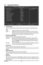
... to AHCI mode. 2-6 Integrated Peripherals CMOS Setup Utility-Copyright (C) 1984-2009 Award Software Integrated Peripherals SATA AHCI Mode SATA Port0-3 Native Mode Azalia Codec Onboard H/W LAN Green LAN } SMART LAN Onboard LAN Boot ROM Onboard USB 3.0 Controller Onboard IDE Controller Onboard Serial Port 1 Onboard Parallel Port Parallel Port Mode USB 1.0 Controller USB 2.0 Controller USB Keyboard Support USB Mouse Support USB Storage Function [IDE] [Disabled] [Auto] [Enabled] [Disabled] [Press Enter] [Disabled] [Enabled] [Enabled] [3F8...
... to AHCI mode. 2-6 Integrated Peripherals CMOS Setup Utility-Copyright (C) 1984-2009 Award Software Integrated Peripherals SATA AHCI Mode SATA Port0-3 Native Mode Azalia Codec Onboard H/W LAN Green LAN } SMART LAN Onboard LAN Boot ROM Onboard USB 3.0 Controller Onboard IDE Controller Onboard Serial Port 1 Onboard Parallel Port Parallel Port Mode USB 1.0 Controller USB 2.0 Controller USB Keyboard Support USB Mouse Support USB Storage Function [IDE] [Disabled] [Auto] [Enabled] [Disabled] [Press Enter] [Disabled] [Enabled] [Enabled] [3F8...

Manual
Page 50
... Port Mode Selects an operating mode for the onboard parallel (LPT) port. Options are : Auto, 3F8/IRQ4 (default), 2F8/IRQ3, 3E8/IRQ4, 2E8/IRQ3, Disabled. Options are: 378/IRQ7 (default), 278/IRQ5, 3BC/IRQ7, Disabled. USB 2.0 Controller Enables or disables the integrated USB 2.0 controller. (Default: Enabled) USB Keyboard Function Allows USB keyboard to be used in MS-DOS. (Default: Disabled) USB Mouse Function Allows USB mouse to detect USB storage devices, including USB flash drives and USB hard drives during the POST. (Default: Enabled) BIOS Setup - 50 - Onboard LAN Boot ROM...
... Port Mode Selects an operating mode for the onboard parallel (LPT) port. Options are : Auto, 3F8/IRQ4 (default), 2F8/IRQ3, 3E8/IRQ4, 2E8/IRQ3, Disabled. Options are: 378/IRQ7 (default), 278/IRQ5, 3BC/IRQ7, Disabled. USB 2.0 Controller Enables or disables the integrated USB 2.0 controller. (Default: Enabled) USB Keyboard Function Allows USB keyboard to be used in MS-DOS. (Default: Disabled) USB Mouse Function Allows USB mouse to detect USB storage devices, including USB flash drives and USB hard drives during the POST. (Default: Enabled) BIOS Setup - 50 - Onboard LAN Boot ROM...

Manual
Page 54
.... (Default: Disabled) Case Opened Displays the detection status of the chassis intrusion detection device attached to the motherboard CI header. CPU Warning Temperature Sets the warning threshold for CPU temperature. Current CPU/SYSTEM/POWER FAN Speed (RPM) Displays current CPU/system/power fan speed. Options are: Disabled (default), 60oC/140oF, 70oC/158oF, 80oC/176oF, 90oC/194oF. To clear the chassis intrusion status record, set Reset Case Open Status to Enabled, save the settings to emit warning sound if the CPU/system/power fan is removed, this occurs. (Default: Disabled) BIOS Setup...
.... (Default: Disabled) Case Opened Displays the detection status of the chassis intrusion detection device attached to the motherboard CI header. CPU Warning Temperature Sets the warning threshold for CPU temperature. Current CPU/SYSTEM/POWER FAN Speed (RPM) Displays current CPU/system/power fan speed. Options are: Disabled (default), 60oC/140oF, 70oC/158oF, 80oC/176oF, 90oC/194oF. To clear the chassis intrusion status record, set Reset Case Open Status to Enabled, save the settings to emit warning sound if the CPU/system/power fan is removed, this occurs. (Default: Disabled) BIOS Setup...
Manual
Page 59
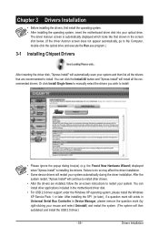
... screen does not appear automatically, go to do so may affect the driver installation. • Some device drivers will install all the drivers that shown in the motherboard driver disk. • For USB 2.0 driver support under the Windows XP operating system, please install the Windows XP Service Pack 1 or later. Or click Install Single Items to manually select the drivers you wish to install. You can click the Install All button and "Xpress Install...
... screen does not appear automatically, go to do so may affect the driver installation. • Some device drivers will install all the drivers that shown in the motherboard driver disk. • For USB 2.0 driver support under the Windows XP operating system, please install the Windows XP Service Pack 1 or later. Or click Install Single Items to manually select the drivers you wish to install. You can click the Install All button and "Xpress Install...
Manual
Page 66
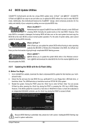
... BIOS update file is @BIOS™? @BIOS allows you can access Q-Flash by adding one more physical BIOS chip. 4-2 BIOS Update Utilities GIGABYTE motherboards provide two unique BIOS update tools, Q-Flash™ and @BIOS™. For the sake of your motherboard model. 2. ep43tusb3.f1) to access Q-Flash. Motherboards that matches your computer by either pressing the key during the POST to your floppy disk, USB flash drive, or hard drive. Note: The USB flash drive or hard drive must use and allow you from the nearest @BIOS server 4-2-1 Updating the BIOS...
... BIOS update file is @BIOS™? @BIOS allows you can access Q-Flash by adding one more physical BIOS chip. 4-2 BIOS Update Utilities GIGABYTE motherboards provide two unique BIOS update tools, Q-Flash™ and @BIOS™. For the sake of your motherboard model. 2. ep43tusb3.f1) to access Q-Flash. Motherboards that matches your computer by either pressing the key during the POST to your floppy disk, USB flash drive, or hard drive. Note: The USB flash drive or hard drive must use and allow you from the nearest @BIOS server 4-2-1 Updating the BIOS...

Manual
Page 67
... the BIOS update file is saved to a hard drive in RAID/AHCI mode or a hard drive attached to an independent IDE/SATA controller, use the key during the POST to the main menu. appears, press to a floppy disk. Updating the BIOS When updating the BIOS, choose the location where the BIOS file is complete, press any key to return to access Q-Flash. 2. Insert the floppy disk containing the BIOS file into the floppy disk drive. Q-Flash Utility v2.13 Flash Type/Size MXIC 25L8005 1M Keep0 DfilMe(Is)DfaotuandEnable Floppy A Loa d CMO S Default Enable HDD 1-0 Upda te BIOS...
... the BIOS update file is saved to a hard drive in RAID/AHCI mode or a hard drive attached to an independent IDE/SATA controller, use the key during the POST to the main menu. appears, press to a floppy disk. Updating the BIOS When updating the BIOS, choose the location where the BIOS file is complete, press any key to return to access Q-Flash. 2. Insert the floppy disk containing the BIOS file into the floppy disk drive. Q-Flash Utility v2.13 Flash Type/Size MXIC 25L8005 1M Keep0 DfilMe(Is)DfaotuandEnable Floppy A Loa d CMO S Default Enable HDD 1-0 Upda te BIOS...
Manual
Page 84
... changes. eral > System). A: The following Award BIOS beep code descriptions may help you identify possible computer problems. (For reference only.) 1 short: System boots successfully 1 long, 3 short: Keyboard error 2 short: CMOS setting error 1 long, 9 short: BIOS ROM error 1 long, 1 short: Memory or motherboard error Continuous long beeps: Graphics card not inserted properly 1 long, 2 short: Monitor or graphics card error Continuous short beeps: Power error Appendix - 84 - A: Some advanced options are some BIOS options missing? If not, try a speaker with an internal...
... changes. eral > System). A: The following Award BIOS beep code descriptions may help you identify possible computer problems. (For reference only.) 1 short: System boots successfully 1 long, 3 short: Keyboard error 2 short: CMOS setting error 1 long, 9 short: BIOS ROM error 1 long, 1 short: Memory or motherboard error Continuous long beeps: Graphics card not inserted properly 1 long, 2 short: Monitor or graphics card error Continuous short beeps: Power error Appendix - 84 - A: Some advanced options are some BIOS options missing? If not, try a speaker with an internal...


