Manual
Page 1
GA-EP43T-USB3 LGA775 socket motherboard for Intel® Core™ processor family/ Intel® Pentium® processor family/Intel® Celeron® processor family User's Manual Rev. 1001 12ME-43TUSB3-1001R
GA-EP43T-USB3 LGA775 socket motherboard for Intel® Core™ processor family/ Intel® Pentium® processor family/Intel® Celeron® processor family User's Manual Rev. 1001 12ME-43TUSB3-1001R
Manual
Page 2
Motherboard GA-EP43T-USB3 Dec. 24, 2009 Motherboard GA-EP43T-USB3 Dec. 24, 2009
Motherboard GA-EP43T-USB3 Dec. 24, 2009 Motherboard GA-EP43T-USB3 Dec. 24, 2009
Manual
Page 3
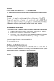
...made by copyright laws and is the property of the motherboard is protected by GIGABYTE without GIGABYTE's prior written permission. For detailed product information, carefully read or download the information on/from the Support&Downloads\Motherboard\Technology Guide page on our website. Example: The ...form or by any means without prior notice. For product-related information, check on our website at: http://www.gigabyte.com.tw Identifying Your Motherboard Revision The revision number on how to assist in this manual is 1.0. Changes to their respective owners. Copyright &#...
...made by copyright laws and is the property of the motherboard is protected by GIGABYTE without GIGABYTE's prior written permission. For detailed product information, carefully read or download the information on/from the Support&Downloads\Motherboard\Technology Guide page on our website. Example: The ...form or by any means without prior notice. For product-related information, check on our website at: http://www.gigabyte.com.tw Identifying Your Motherboard Revision The revision number on how to assist in this manual is 1.0. Changes to their respective owners. Copyright &#...
Manual
Page 4
Table of Contents Box Contents...6 Optional Items...6 GA-EP43T-USB3 Motherboard Layout 7 GA-EP43T-USB3 Motherboard Block Diagram 8 Chapter 1 Hardware Installation 9 1-1 Installation Precautions 9 1-2 Product Specifications 10 1-3 Installing the CPU and CPU Cooler 13 1-3-1 Installing the CPU 13 1-3-2 Installing the CPU Cooler ...
Table of Contents Box Contents...6 Optional Items...6 GA-EP43T-USB3 Motherboard Layout 7 GA-EP43T-USB3 Motherboard Block Diagram 8 Chapter 1 Hardware Installation 9 1-1 Installation Precautions 9 1-2 Product Specifications 10 1-3 Installing the CPU and CPU Cooler 13 1-3-1 Installing the CPU 13 1-3-2 Installing the CPU Cooler ...
Manual
Page 6
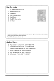
Box Contents GA-EP43T-USB3 motherboard Motherboard driver disk User's Manual Quick Installation Guide One IDE cable Two SATA 3Gb/s cables I/O Shield • The box contents above are subject to change without notice. • The motherboard image is for reference only and the actual items shall depend on the product package you obtain. The box contents are...
Box Contents GA-EP43T-USB3 motherboard Motherboard driver disk User's Manual Quick Installation Guide One IDE cable Two SATA 3Gb/s cables I/O Shield • The box contents above are subject to change without notice. • The motherboard image is for reference only and the actual items shall depend on the product package you obtain. The box contents are...
Manual
Page 7
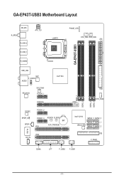
GA-EP43T-USB3 Motherboard Layout GA-EP43T-USB3 KB_MS R_SPDIF R_USB_2 R_USB_1 R_USB30 ATX_12V LGA775 PHASE_LED CPU_FAN PWR_FAN ATX USB_LAN NEC F_AUDIO AUDIO RTL8111D SYS_FAN1 PCIEX1_1 Intel® P43 PCIEX16 CODEC SPDIF_O SPDIF_I PCIEX1_2 PCIEX1_3 M_BIOS B_BIOS BAT CLR_CMOS PCI1 IT8718 PCI2 CD_IN FDD SYS_FAN2 DDR3_1 DDR3_2 DDR3_3 DDR3_4 Intel® ICH10 SATA2_3 SATA2_0 SATA2_4 SATA2_1 JMicron 368 SATA2_5 SATA2_2 IDE F_PANEL COMA LPT F_USB2 F_USB1 - 7 -
GA-EP43T-USB3 Motherboard Layout GA-EP43T-USB3 KB_MS R_SPDIF R_USB_2 R_USB_1 R_USB30 ATX_12V LGA775 PHASE_LED CPU_FAN PWR_FAN ATX USB_LAN NEC F_AUDIO AUDIO RTL8111D SYS_FAN1 PCIEX1_1 Intel® P43 PCIEX16 CODEC SPDIF_O SPDIF_I PCIEX1_2 PCIEX1_3 M_BIOS B_BIOS BAT CLR_CMOS PCI1 IT8718 PCI2 CD_IN FDD SYS_FAN2 DDR3_1 DDR3_2 DDR3_3 DDR3_4 Intel® ICH10 SATA2_3 SATA2_0 SATA2_4 SATA2_1 JMicron 368 SATA2_5 SATA2_2 IDE F_PANEL COMA LPT F_USB2 F_USB1 - 7 -
Manual
Page 8
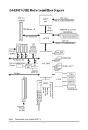
GA-EP43T-USB3 Motherboard Block Diagram PCIe CLK (100 MHz) LGA775 CPU CPU CLK+/(400 (O.C.)/333/266/200 MHz) 1 PCI Express x16 PCI Express x16 3 PCI Express x1 LAN ...
GA-EP43T-USB3 Motherboard Block Diagram PCIe CLK (100 MHz) LGA775 CPU CPU CLK+/(400 (O.C.)/333/266/200 MHz) 1 PCI Express x16 PCI Express x16 3 PCI Express x1 LAN ...
Manual
Page 9
... electrostatic shielding container. • Before unplugging the power supply cable from the power outlet before installing or removing the motherboard or other hardware components. • When connecting hardware components to the internal connectors on the computer power during the ...best to wear an electrostatic discharge (ESD) wrist strap when handling electronic com- Chapter 1 Hardware Installation 1-1 Installation Precautions The motherboard contains numerous delicate electronic circuits and components which can lead to damage to system components as well as physical harm to the ...
... electrostatic shielding container. • Before unplugging the power supply cable from the power outlet before installing or removing the motherboard or other hardware components. • When connecting hardware components to the internal connectors on the computer power during the ...best to wear an electrostatic discharge (ESD) wrist strap when handling electronic com- Chapter 1 Hardware Installation 1-1 Installation Precautions The motherboard contains numerous delicate electronic circuits and components which can lead to damage to system components as well as physical harm to the ...
Manual
Page 12
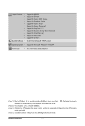
... CPU/system fan speed control function is supported will depend on the CPU/system cooler you install. (Note 4) Available functions in EasyTune may differ by motherboard model. Hardware Installation - 12 -
... CPU/system fan speed control function is supported will depend on the CPU/system cooler you install. (Note 4) Available functions in EasyTune may differ by motherboard model. Hardware Installation - 12 -
Manual
Page 13
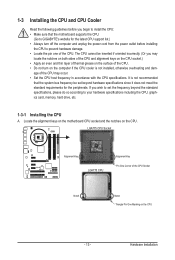
... standard requirements for the latest CPU support list.) • Always turn on the computer if the CPU cooler is not recommended that the motherboard supports the CPU. (Go to GIGABYTE's website for the peripherals. LGA775 CPU Socket Alignment Key LGA775 CPU Alignment Key Pin One Corner of the CPU. If you may... damage. • Locate the pin one of the CPU Socket Notch Notch Triangle Pin One Marking on the CPU. Locate the alignment keys on the motherboard CPU socket and the notches on the CPU - 13 -
... standard requirements for the latest CPU support list.) • Always turn on the computer if the CPU cooler is not recommended that the motherboard supports the CPU. (Go to GIGABYTE's website for the peripherals. LGA775 CPU Socket Alignment Key LGA775 CPU Alignment Key Pin One Corner of the CPU. If you may... damage. • Locate the pin one of the CPU Socket Notch Notch Triangle Pin One Marking on the CPU. Locate the alignment keys on the motherboard CPU socket and the notches on the CPU - 13 -
Manual
Page 14
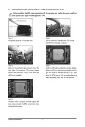
... Installation - 14 - Step 5: Once the CPU is not installed.) Step 4: Hold the CPU with the socket alignment keys) and gently insert the CPU into the motherboard CPU socket. Before installing the CPU, make sure to the CPU.
... Installation - 14 - Step 5: Once the CPU is not installed.) Step 4: Hold the CPU with the socket alignment keys) and gently insert the CPU into the motherboard CPU socket. Before installing the CPU, make sure to the CPU.
Manual
Page 15
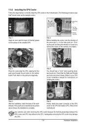
... Before installing the cooler, note the direction of the arrow sign on the male push pin. (Turning the push pin along the direction of the motherboard. Use extreme care when removing the CPU cooler because the thermal grease/tape between the CPU cooler and CPU may damage the CPU. - 15 -...the CPU cooler may adhere to install.) Step 3: Place the cooler atop the CPU, aligning the four push pins through the pin holes on the motherboard. Step 6: Finally, attach the power connector of the CPU cooler to your CPU cooler installation manual for instructions on installing the cooler.) Step 5: ...
... Before installing the cooler, note the direction of the arrow sign on the male push pin. (Turning the push pin along the direction of the motherboard. Use extreme care when removing the CPU cooler because the thermal grease/tape between the CPU cooler and CPU may damage the CPU. - 15 -...the CPU cooler may adhere to install.) Step 3: Place the cooler atop the CPU, aligning the four push pins through the pin holes on the motherboard. Step 6: Finally, attach the power connector of the CPU cooler to your CPU cooler installation manual for instructions on installing the cooler.) Step 5: ...
Manual
Page 16
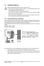
...Memory Configurations Table DDR3_1 DDR3_2 DDR3_3 DDR3_4 Two Modules DS/SS - - Dual Channel mode cannot be used . (Go to GIGABYTE's website for optimum performance. 1-4 Installing the Memory Read the following guidelines before you are divided into two channels and each ...Sided, "- -"=No Memory) DDR3_1 DDR3_2 DDR3_3 DDR3_4 Due to insert the memory, switch the direction. 1-4-1 Dual Channel Memory Configuration This motherboard provides four DDR3 memory sockets and supports Dual Channel Technology. Hardware Installation - 16 - It is installed. 2. DS/SS - - After...
...Memory Configurations Table DDR3_1 DDR3_2 DDR3_3 DDR3_4 Two Modules DS/SS - - Dual Channel mode cannot be used . (Go to GIGABYTE's website for optimum performance. 1-4 Installing the Memory Read the following guidelines before you are divided into two channels and each ...Sided, "- -"=No Memory) DDR3_1 DDR3_2 DDR3_3 DDR3_4 Due to insert the memory, switch the direction. 1-4-1 Dual Channel Memory Configuration This motherboard provides four DDR3 memory sockets and supports Dual Channel Technology. Hardware Installation - 16 - It is installed. 2. DS/SS - - After...
Manual
Page 17
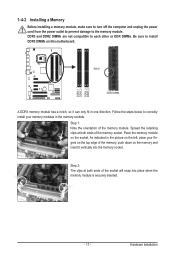
... in one direction. DDR3 and DDR2 DIMMs are not compatible to each other or DDR DIMMs. Be sure to correctly install your fingers on this motherboard. Hardware Installation Notch DDR3 DIMM A DDR3 memory module has a notch, so it vertically into place when the memory module is securely inserted. - 17 - DDR3_1 DDR3_2...
... in one direction. DDR3 and DDR2 DIMMs are not compatible to each other or DDR DIMMs. Be sure to correctly install your fingers on this motherboard. Hardware Installation Notch DDR3 DIMM A DDR3 memory module has a notch, so it vertically into place when the memory module is securely inserted. - 17 - DDR3_1 DDR3_2...
Manual
Page 18
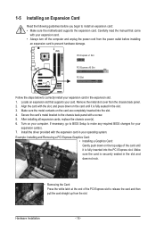
... expansion slot. 1. PCI Express x1 Slot PCI Express x16 Slot PCI Slot Follow the steps below to install an expansion card: • Make sure the motherboard supports the expansion card. Carefully read the manual that supports your operating system. 1-5 Installing an Expansion Card Read the following guidelines before installing an expansion...
... expansion slot. 1. PCI Express x1 Slot PCI Express x16 Slot PCI Slot Follow the steps below to install an expansion card: • Make sure the motherboard supports the expansion card. Carefully read the manual that supports your operating system. 1-5 Installing an Expansion Card Read the following guidelines before installing an expansion...
Manual
Page 19
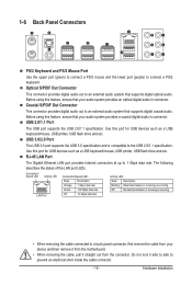
... a back panel connector, first remove the cable from your audio system provides a coaxial digital audio in connector. Do not rock it straight out from the motherboard. • When removing the cable, pull it side to side to connect a PS/2 keyboard. Before using this feature, ensure that supports digital coaxial audio. USB...
... a back panel connector, first remove the cable from your audio system provides a coaxial digital audio in connector. Do not rock it straight out from the motherboard. • When removing the cable, pull it side to side to connect a PS/2 keyboard. Before using this feature, ensure that supports digital coaxial audio. USB...
Manual
Page 21
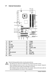
... 12) F_AUDIO 13) SPDIF_I 14) SPDIF_O 15) F_USB1/F_USB2 16) LPT 17) COMA 18) CLR_CMOS 19) PHASE_LED Read the following guidelines before turning on the motherboard. - 21 - Unplug the power cord from the power outlet to prevent damage to the devices. • After installing the device and before connecting external devices...
... 12) F_AUDIO 13) SPDIF_I 14) SPDIF_O 15) F_USB1/F_USB2 16) LPT 17) COMA 18) CLR_CMOS 19) PHASE_LED Read the following guidelines before turning on the motherboard. - 21 - Unplug the power cord from the power outlet to prevent damage to the devices. • After installing the device and before connecting external devices...
Manual
Page 22
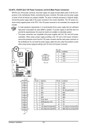
...or greater). Connect the power supply cable to the CPU. If a power supply is turned off and all the components on the motherboard. Do not insert the power supply cables into pins under the protective covers when using a power supply providing a 2x4 12V and... a 2x12 power connector, remove the protective covers from the 12V power connector and the main power connector on the motherboard. The power connector possesses a foolproof design. When using a power supply providing a 2x2 12V and a 2x10 power connector. 3 4 1 2 ATX_12V ATX_12V: Pin No...
...or greater). Connect the power supply cable to the CPU. If a power supply is turned off and all the components on the motherboard. Do not insert the power supply cables into pins under the protective covers when using a power supply providing a 2x4 12V and... a 2x12 power connector, remove the protective covers from the 12V power connector and the main power connector on the motherboard. The power connector possesses a foolproof design. When using a power supply providing a 2x2 12V and a 2x10 power connector. 3 4 1 2 ATX_12V ATX_12V: Pin No...
Manual
Page 23
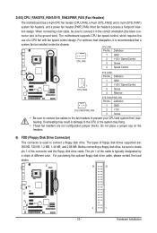
Most fan headers possess a foolproof inser- tion design. The motherboard supports CPU fan speed control, which requires the use of floppy disk drives supported are not configuration jumper blocks. Definition 1 CPU_FAN 1 GND 2 +12V / Speed Control 3 ... to connect fan cables to the fan headers to locate pin 1 of the cable is the ground wire). 3/4/5) CPU_FAN/SYS_FAN1/SYS_FAN2/PWR_FAN (Fan Headers) The motherboard has a 4-pin CPU fan header (CPU_FAN), a 4-pin (SYS_FAN2) and a 3-pin (SYS_FAN1) system fan headers, and a power fan header (PWR_FAN...
Most fan headers possess a foolproof inser- tion design. The motherboard supports CPU fan speed control, which requires the use of floppy disk drives supported are not configuration jumper blocks. Definition 1 CPU_FAN 1 GND 2 +12V / Speed Control 3 ... to connect fan cables to the fan headers to locate pin 1 of the cable is the ground wire). 3/4/5) CPU_FAN/SYS_FAN1/SYS_FAN2/PWR_FAN (Fan Headers) The motherboard has a 4-pin CPU fan header (CPU_FAN), a 4-pin (SYS_FAN2) and a 3-pin (SYS_FAN1) system fan headers, and a power fan header (PWR_FAN...
Manual
Page 27
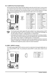
... Chapter 5, "Configuring 2/4/5.1/7.1-Channel Audio." • Some chassis provide a front panel audio module that has separated connectors on each wire instead of the motherboard header. Definition 1 Power 2 SPDIFI 3 GND - 27 - Make sure the wire assignments of the module connector match the pin assignments of a ...panel audio connections simultaneously. Definition For AC'97 Front Panel Audio: Pin No. Incorrect connection between the module connector and the motherboard header will be present on how to this header. If you want to mute the back panel audio (only supported when ...
... Chapter 5, "Configuring 2/4/5.1/7.1-Channel Audio." • Some chassis provide a front panel audio module that has separated connectors on each wire instead of the motherboard header. Definition 1 Power 2 SPDIFI 3 GND - 27 - Make sure the wire assignments of the module connector match the pin assignments of a ...panel audio connections simultaneously. Definition For AC'97 Front Panel Audio: Pin No. Incorrect connection between the module connector and the motherboard header will be present on how to this header. If you want to mute the back panel audio (only supported when ...


