Manual
Page 3
...your motherboard looks like this manual may be made by copyright laws and is the property of the motherboard is protected by GIGABYTE without GIGABYTE's prior written permission. Copyright © 2009 GIGA-BYTE TECHNOLOGY CO., LTD. All rights reserved. The trademarks mentioned in...on how to the specifications and features in the use GIGABYTE's unique features, read or download the information on/from the Support&Downloads\Motherboard\Technology Guide page on your motherboard revision before updating motherboard BIOS, drivers, or when looking for technical information. No ...
...your motherboard looks like this manual may be made by copyright laws and is the property of the motherboard is protected by GIGABYTE without GIGABYTE's prior written permission. Copyright © 2009 GIGA-BYTE TECHNOLOGY CO., LTD. All rights reserved. The trademarks mentioned in...on how to the specifications and features in the use GIGABYTE's unique features, read or download the information on/from the Support&Downloads\Motherboard\Technology Guide page on your motherboard revision before updating motherboard BIOS, drivers, or when looking for technical information. No ...
Manual
Page 4
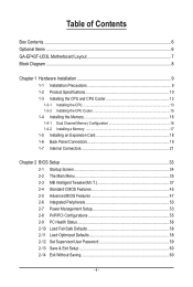
Table of Contents Box Contents...6 Optional Items...6 GA-EP43T-UD3L Motherboard Layout 7 Block Diagram...8 Chapter 1 Hardware Installation 9 1-1 Installation Precautions 9 1-2 Product Specifications 10 1-3 Installing the CPU and CPU Cooler ... Installing an Expansion Card 18 1-6 Back Panel Connectors 19 1-7 Internal Connectors 21 Chapter 2 BIOS Setup 33 2-1 Startup Screen 34 2-2 The Main Menu 35 2-3 MB Intelligent Tweaker(M.I.T 37 2-4 Standard CMOS Features 45 2-5 Advanced BIOS Features 47 2-6 Integrated Peripherals 50 2-7 Power Management Setup 53 2-8 PnP/PCI Configurations 55 ...
Table of Contents Box Contents...6 Optional Items...6 GA-EP43T-UD3L Motherboard Layout 7 Block Diagram...8 Chapter 1 Hardware Installation 9 1-1 Installation Precautions 9 1-2 Product Specifications 10 1-3 Installing the CPU and CPU Cooler ... Installing an Expansion Card 18 1-6 Back Panel Connectors 19 1-7 Internal Connectors 21 Chapter 2 BIOS Setup 33 2-1 Startup Screen 34 2-2 The Main Menu 35 2-3 MB Intelligent Tweaker(M.I.T 37 2-4 Standard CMOS Features 45 2-5 Advanced BIOS Features 47 2-6 Integrated Peripherals 50 2-7 Power Management Setup 53 2-8 PnP/PCI Configurations 55 ...
Manual
Page 5
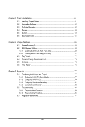
... 62 3-3 Technical Manuals 62 3-4 Contact...63 3-5 System...63 3-6 Download Center 64 Chapter 4 Unique Features 65 4-1 Xpress Recovery2 65 4-2 BIOS Update Utilities 68 4-2-1 Updating the BIOS with the Q-Flash Utility 68 4-2-2 Updating the BIOS with the @BIOS Utility 71 4-3 EasyTune 6...72 4-4 Dynamic Energy Saver Advanced 73 4-5 Q-Share...75 4-6 Time Repair...76 Chapter 5 Appendix...77 5-1 Configuring...
... 62 3-3 Technical Manuals 62 3-4 Contact...63 3-5 System...63 3-6 Download Center 64 Chapter 4 Unique Features 65 4-1 Xpress Recovery2 65 4-2 BIOS Update Utilities 68 4-2-1 Updating the BIOS with the Q-Flash Utility 68 4-2-2 Updating the BIOS with the @BIOS Utility 71 4-3 EasyTune 6...72 4-4 Dynamic Energy Saver Advanced 73 4-5 Q-Share...75 4-6 Time Repair...76 Chapter 5 Appendix...77 5-1 Configuring...
Manual
Page 8
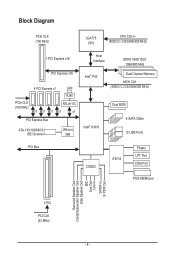
... Host Interface DDR3 1600/1333/ 1066/800 MHz Intel® P43 Dual Channel Memory MCH CLK (400(O.C.)/333/266/200 MHz) Intel® ICH10 Dual BIOS 6 SATA 3Gb/s 12 USB Ports PCI Bus CODEC IT8718 Floppy LPT Port COM Port PS/2 KB/Mouse Surround Speaker Out Center/Subwoofer Speaker Out Side...
... Host Interface DDR3 1600/1333/ 1066/800 MHz Intel® P43 Dual Channel Memory MCH CLK (400(O.C.)/333/266/200 MHz) Intel® ICH10 Dual BIOS 6 SATA 3Gb/s 12 USB Ports PCI Bus CODEC IT8718 Floppy LPT Port COM Port PS/2 KB/Mouse Surround Speaker Out Center/Subwoofer Speaker Out Side...
Manual
Page 12
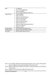
GA-EP43T-UD3L Motherboard - 12 - BIOS Unique Features Bundled Software Operating System Form Factor w 2 x 8 Mbit flash w Use of licensed AWARD BIOS w Support for DualBIOS™ w PnP 1.0a, DMI 2.0, SM BIOS 2.4, ACPI 1.0b w Support for @BIOS w Support for Q-Flash w Support for Xpress BIOS Rescue w Support for Download Center w Support for Xpress Install w Support for Xpress Recovery2 w Support for EasyTune (Note...
GA-EP43T-UD3L Motherboard - 12 - BIOS Unique Features Bundled Software Operating System Form Factor w 2 x 8 Mbit flash w Use of licensed AWARD BIOS w Support for DualBIOS™ w PnP 1.0a, DMI 2.0, SM BIOS 2.4, ACPI 1.0b w Support for @BIOS w Support for Q-Flash w Support for Xpress BIOS Rescue w Support for Download Center w Support for Xpress Install w Support for Xpress Recovery2 w Support for EasyTune (Note...
Manual
Page 16
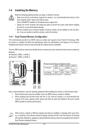
...Channel mode with two or four memory modules, it is operating in Dual Channel mode/performance. A memory module can be used . (Go to GIGABYTE's website for optimum performance. DS/SS Four Modules DS/SS DS/SS DS/SS DS/SS (SS=Single-Sided, DS=Double-Sided, "- -"=... DDR3_4 Two Modules DS/SS - - Dual Channel mode cannot be used and installed in only one DDR3 memory module is installed, the BIOS will double the original memory bandwidth. GA-EP43T-UD3L Motherboard - 16 - After the memory is installed. 2. DS/SS - - - - 1-4 Installing the Memory Read the following guidelines ...
...Channel mode with two or four memory modules, it is operating in Dual Channel mode/performance. A memory module can be used . (Go to GIGABYTE's website for optimum performance. DS/SS Four Modules DS/SS DS/SS DS/SS DS/SS (SS=Single-Sided, DS=Double-Sided, "- -"=... DDR3_4 Two Modules DS/SS - - Dual Channel mode cannot be used and installed in only one DDR3 memory module is installed, the BIOS will double the original memory bandwidth. GA-EP43T-UD3L Motherboard - 16 - After the memory is installed. 2. DS/SS - - - - 1-4 Installing the Memory Read the following guidelines ...
Manual
Page 18
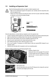
... installing all expansion cards, replace the chassis cover(s). 6. Make sure the card is securely seated in the expansion slot. 1. GA-EP43T-UD3L Motherboard - 18 - If necessary, go to BIOS Setup to correctly install your card. PCI Express x1 Slot PCI Express x16 Slot PCI Slot Follow the steps below to make... any required BIOS changes for your computer. Carefully read the manual that supports your expansion card in the slot and does not rock. • Removing...
... installing all expansion cards, replace the chassis cover(s). 6. Make sure the card is securely seated in the expansion slot. 1. GA-EP43T-UD3L Motherboard - 18 - If necessary, go to BIOS Setup to correctly install your card. PCI Express x1 Slot PCI Express x16 Slot PCI Slot Follow the steps below to make... any required BIOS changes for your computer. Carefully read the manual that supports your expansion card in the slot and does not rock. • Removing...
Manual
Page 25
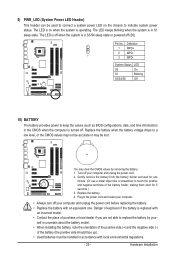
..., making them short for one . Hardware Installation The LED is off . Replace the battery when the battery voltage drops to keep the values (such as BIOS configurations, date, and time information) in the power cord and restart your computer. • Always turn off your computer and unplug the power cord. 2. Plug...
..., making them short for one . Hardware Installation The LED is off . Replace the battery when the battery voltage drops to keep the values (such as BIOS configurations, date, and time information) in the power cord and restart your computer. • Always turn off your computer and unplug the power cord. 2. Plug...
Manual
Page 26
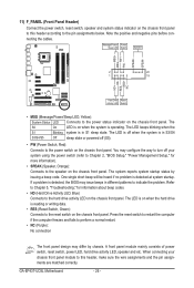
... etc. When connecting your system using the power switch (refer to Chapter 2, "BIOS Setup," "Power Management Setup," for information about beep codes. • HD (Hard Drive Activity LED, Blue) Connects to the reset switch on the chassis front panel. GA-EP43T-UD3L Motherboard - 26 - Message/Power/ Power Sleep LED Switch Speaker MSG+ MSG- PW... indicate the problem. Note the positive and negative pins before connecting the cables. The LED keeps blinking when the S1 Blinking system is detected, the BIOS may differ by issuing a beep code.
... etc. When connecting your system using the power switch (refer to Chapter 2, "BIOS Setup," "Power Management Setup," for information about beep codes. • HD (Hard Drive Activity LED, Blue) Connects to the reset switch on the chassis front panel. GA-EP43T-UD3L Motherboard - 26 - Message/Power/ Power Sleep LED Switch Speaker MSG+ MSG- PW... indicate the problem. Note the positive and negative pins before connecting the cables. The LED keeps blinking when the S1 Blinking system is detected, the BIOS may differ by issuing a beep code.
Manual
Page 31
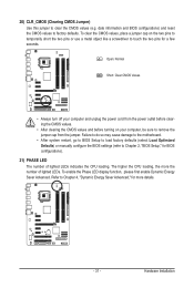
...for more the number of lighted LEDs indicates the CPU loading. The higher the CPU loading, the more details. - 31 - date information and BIOS configurations) and reset the CMOS values to clear the CMOS values (e.g. Failure to do so may cause damage to the motherboard. • After system...the CMOS values and before turning on the two pins to temporarily short the two pins or use a metal object like a screwdriver to Chapter 2, "BIOS Setup," for a few seconds. To enable the Phase LED display function, please first enable Dynamic Energy Saver Advanced. 20) CLR_CMOS (Clearing CMOS Jumper)...
...for more the number of lighted LEDs indicates the CPU loading. The higher the CPU loading, the more details. - 31 - date information and BIOS configurations) and reset the CMOS values to clear the CMOS values (e.g. Failure to do so may cause damage to the motherboard. • After system...the CMOS values and before turning on the two pins to temporarily short the two pins or use a metal object like a screwdriver to Chapter 2, "BIOS Setup," for a few seconds. To enable the Phase LED display function, please first enable Dynamic Energy Saver Advanced. 20) CLR_CMOS (Clearing CMOS Jumper)...
Manual
Page 33
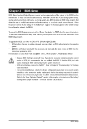
To upgrade the BIOS, use either the GIGABYTE Q-Flash or @BIOS utility. • Q-Flash allows the user to quickly and easily upgrade or back up BIOS without entering the operating system. • @BIOS is recommended that searches and downloads the latest version of BIOS from the Internet and updates the BIOS. To flash the BIOS, do not encounter problems...
To upgrade the BIOS, use either the GIGABYTE Q-Flash or @BIOS utility. • Q-Flash allows the user to quickly and easily upgrade or back up BIOS without entering the operating system. • @BIOS is recommended that searches and downloads the latest version of BIOS from the Internet and updates the BIOS. To flash the BIOS, do not encounter problems...
Manual
Page 34
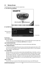
...Screen The following screens may appear when the computer boots. The LOGO Screen (Default) B. To show the BIOS POST screen. Motherboard Model BIOS Version EP43T-UD3L E5a . . . . : BIOS Setup : XpressRecovery2 : Boot Menu : Qflash 04/17/2009-P43-ICH10-7A69PG0TC-00 Function Keys Function Keys ...BIOS Setup settings. For more information, refer to Chapter 4, "Xpress Recovery2." : BOOT MENU Boot Menu allows you have ever entered Xpress Recovery2 to back up arrow key or the down arrow key to select the first boot device, then press to Xpress Recovery2 during the POST. GA-EP43T-UD3L...
...Screen The following screens may appear when the computer boots. The LOGO Screen (Default) B. To show the BIOS POST screen. Motherboard Model BIOS Version EP43T-UD3L E5a . . . . : BIOS Setup : XpressRecovery2 : Boot Menu : Qflash 04/17/2009-P43-ICH10-7A69PG0TC-00 Function Keys Function Keys ...BIOS Setup settings. For more information, refer to Chapter 4, "Xpress Recovery2." : BOOT MENU Boot Menu allows you have ever entered Xpress Recovery2 to back up arrow key or the down arrow key to select the first boot device, then press to Xpress Recovery2 during the POST. GA-EP43T-UD3L...
Manual
Page 35
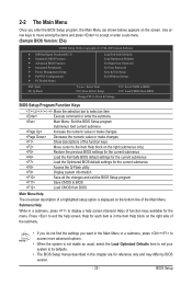
... Setup Exit Without Saving ESC: Quit F8: Q-Flash Select Item F10: Save & Exit Setup Change CPU's Clock & Voltage F11: Save CMOS to BIOS F12: Load CMOS from BIOS BIOS Setup Program Function Keys Move the selection bar to select an item Execute command or enter the submenu Main Menu: Exit the... The on-screen description of a highlighted setup option is displayed on the bottom line of function keys available for reference only and may differ by BIOS version. - 35 - 2-2 The Main Menu Once you want in the Main Menu or a submenu, press + to access more advanced options. • ...
... Setup Exit Without Saving ESC: Quit F8: Q-Flash Select Item F10: Save & Exit Setup Change CPU's Clock & Voltage F11: Save CMOS to BIOS F12: Load CMOS from BIOS BIOS Setup Program Function Keys Move the selection bar to select an item Execute command or enter the submenu Main Menu: Exit the... The on-screen description of a highlighted setup option is displayed on the bottom line of function keys available for reference only and may differ by BIOS version. - 35 - 2-2 The Main Menu Once you want in the Main Menu or a submenu, press + to access more advanced options. • ...
Manual
Page 36
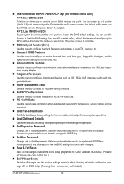
...access to the confirmation message will exit BIOS Setup. (Pressing can also carry out this task.) Exit Without Saving Abandon all the changes made in effect. First enter the profile name (to erase the default profile name, use this task.) GA-EP43T-UD3L Motherboard - 36 - You can ...use the SPACE key) and then press to complete. F12: Load CMOS from a profile created before, without the hassles of errors that stop the system boot, etc. Advanced BIOS Features Use this menu to ...
...access to the confirmation message will exit BIOS Setup. (Pressing can also carry out this task.) Exit Without Saving Abandon all the changes made in effect. First enter the profile name (to erase the default profile name, use this task.) GA-EP43T-UD3L Motherboard - 36 - You can ...use the SPACE key) and then press to complete. F12: Load CMOS from a profile created before, without the hassles of errors that stop the system boot, etc. Advanced BIOS Features Use this menu to ...
Manual
Page 37
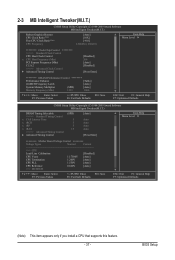
...: Fail-Safe Defaults ESC: Exit F1: General Help F7: Optimized Defaults (Note) This item appears only if you install a CPU that supports this feature. - 37 - BIOS Setup
...: Fail-Safe Defaults ESC: Exit F1: General Help F7: Optimized Defaults (Note) This item appears only if you install a CPU that supports this feature. - 37 - BIOS Setup
Manual
Page 38
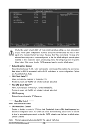
...clock ratio by 0.5 for the installed CPU. Fine CPU Clock Ratio (Note) Allows you to alter the clock ratio for the installed CPU. GA-EP43T-UD3L Motherboard - 38 - Options are: Auto (default), Fast, Turbo. CPU Frequency Displays the current operating CPU frequency. ******** Clock Chip Control Standard...and reset the board to default values.) Robust Graphics Booster Robust Graphics Booster (R.G.B.) helps to automatically set the R.G.B. Auto allows the BIOS to enhance the performance of CPU host clock. mode based on your system fails to boot after overclocking, please wait for 20...
...clock ratio by 0.5 for the installed CPU. Fine CPU Clock Ratio (Note) Allows you to alter the clock ratio for the installed CPU. GA-EP43T-UD3L Motherboard - 38 - Options are: Auto (default), Fast, Turbo. CPU Frequency Displays the current operating CPU frequency. ******** Clock Chip Control Standard...and reset the board to default values.) Robust Graphics Booster Robust Graphics Booster (R.G.B.) helps to automatically set the R.G.B. Auto allows the BIOS to enhance the performance of CPU host clock. mode based on your system fails to boot after overclocking, please wait for 20...

Manual
Page 39
For a 1066 MHz FSB CPU, set this item to 400 MHz. As stability is designed to automatically adjust CPU computing power to maximize system performance. BIOS Setup Auto sets the PCIe clock frequency to standard 100 MHz. (Default: Auto) C.I.A.2 CPU Intelligent Accelerator 2 (C.I .A.2. (Default) Cruise Increases CPU frequency by 5% or 7% depending on ...
For a 1066 MHz FSB CPU, set this item to 400 MHz. As stability is designed to automatically adjust CPU computing power to maximize system performance. BIOS Setup Auto sets the PCIe clock frequency to standard 100 MHz. (Default: Auto) C.I.A.2 CPU Intelligent Accelerator 2 (C.I .A.2. (Default) Cruise Increases CPU frequency by 5% or 7% depending on ...
Manual
Page 41
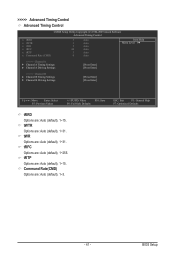
...: Save F6: Fail-Safe Defaults ESC: Exit F1: General Help F7: Optimized Defaults tRRD Options are : Auto (default), 1~31. tWR Options are : Auto (default), 1~15. BIOS Setup Command Rate(CMD) Options are : Auto (default), 1~15. tRTP Options are : Auto (default), 1~3. - 41 - tRFC Options are : Auto (default), 1~31. tWTR Options are : Auto...
...: Save F6: Fail-Safe Defaults ESC: Exit F1: General Help F7: Optimized Defaults tRRD Options are : Auto (default), 1~31. tWR Options are : Auto (default), 1~15. BIOS Setup Command Rate(CMD) Options are : Auto (default), 1~15. tRTP Options are : Auto (default), 1~3. - 41 - tRFC Options are : Auto (default), 1~31. tWTR Options are : Auto...
Manual
Page 43
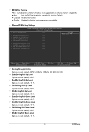
... Level Options are : Auto (default), +8~-7. Cmd Driving Pull-Up Level Options are : Auto (default), +8~-7. Auto Lets the BIOS decide whether to enhance memory compatibility. Ctrl Driving Pull-Down Level Options are : Auto (default), +8~-7. BIOS Setup Clk Driving Pull-Up Level Options are : Auto (default), +8~-7. - 43 - Clk Driving Pull-Down Level Options are...
... Level Options are : Auto (default), +8~-7. Cmd Driving Pull-Up Level Options are : Auto (default), +8~-7. Auto Lets the BIOS decide whether to enhance memory compatibility. Ctrl Driving Pull-Down Level Options are : Auto (default), +8~-7. BIOS Setup Clk Driving Pull-Up Level Options are : Auto (default), +8~-7. - 43 - Clk Driving Pull-Down Level Options are...
Manual
Page 45
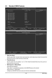
...:ss) Sets the system time. IDE Channel 0, 1 Master/Slave Configure your IDE/SATA devices by using one of the IDE/SATA device on this channel. BIOS Setup Select the desired field and use the up arrow or down arrow key to set the date. Select the desired field and use the...
...:ss) Sets the system time. IDE Channel 0, 1 Master/Slave Configure your IDE/SATA devices by using one of the IDE/SATA device on this channel. BIOS Setup Select the desired field and use the up arrow or down arrow key to set the date. Select the desired field and use the...


