Manual
Page 1
GA-EP43C-DS3 LGA775 socket motherboard for Intel® CoreTM processor family/ Intel® Pentium® processor family/Intel® Celeron® processor family User's Manual Rev. 1001 12ME-EP43CDS3-1001R
GA-EP43C-DS3 LGA775 socket motherboard for Intel® CoreTM processor family/ Intel® Pentium® processor family/Intel® Celeron® processor family User's Manual Rev. 1001 12ME-EP43CDS3-1001R

Manual
Page 2
Motherboard GA-EP43C-DS3 Jul. 30, 2008 Motherboard GA-EP43C-DS3 Jul. 30, 2008
Motherboard GA-EP43C-DS3 Jul. 30, 2008 Motherboard GA-EP43C-DS3 Jul. 30, 2008
Manual
Page 3
...; For detailed product information, carefully read the User's Manual. „ For instructions on how to use GIGABYTE's unique features, read or download the information on/from the Support\Motherboard\Technology Guide page on your motherboard revision before updating motherboard BIOS, drivers, or when looking for technical information. For example, "REV: 1.0" means the revision of...
...; For detailed product information, carefully read the User's Manual. „ For instructions on how to use GIGABYTE's unique features, read or download the information on/from the Support\Motherboard\Technology Guide page on your motherboard revision before updating motherboard BIOS, drivers, or when looking for technical information. For example, "REV: 1.0" means the revision of...
Manual
Page 4
Table of Contents Box Contents ...6 OptionalItems...6 GA-EP43C-DS3 Motherboard Layout 7 Block Diagram...8 Chapter 1 Hardware Installation 9 1-1 Installation Precautions 9 1-2 Product Specifications 10 1-3 Installing the CPU and CPU Cooler 13 1-3-1 Installing the CPU 13 1-3-2 Installing the CPU ...
Table of Contents Box Contents ...6 OptionalItems...6 GA-EP43C-DS3 Motherboard Layout 7 Block Diagram...8 Chapter 1 Hardware Installation 9 1-1 Installation Precautions 9 1-2 Product Specifications 10 1-3 Installing the CPU and CPU Cooler 13 1-3-1 Installing the CPU 13 1-3-2 Installing the CPU ...
Manual
Page 6
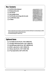
... in cable (Part No. 12CR1-1SPDIN-01R) COM port cable (Part No. 12CF1-1CM001-32R) LPT port cable (Part No. 12CF1-1LP001-01R) - 6 - Box Contents GA-EP43C-DS3 motherboard Motherboard driver disk User's Manual Quick Installation Guide One IDE cable and one floppy disk drive cable Four SATA 3Gb/s cables I/O Shield • The box contents...
... in cable (Part No. 12CR1-1SPDIN-01R) COM port cable (Part No. 12CF1-1CM001-32R) LPT port cable (Part No. 12CF1-1LP001-01R) - 6 - Box Contents GA-EP43C-DS3 motherboard Motherboard driver disk User's Manual Quick Installation Guide One IDE cable and one floppy disk drive cable Four SATA 3Gb/s cables I/O Shield • The box contents...
Manual
Page 7
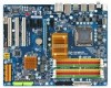
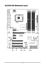
GA-EP43C-DS3 Motherboard Layout KB_MS R_SPDIF ATX_12V_2X4 USB_1394_2 LGA775 USB_1394_1 R_USB CPU_FAN PHASE LED ATX GA-EP43C-DS3 USB_LAN FDD AUDIO F_AUDIO Intel® P43 SYS_FAN1 PCIEX1_1 DDR2_3 DDR2_4 DDR3_2 DDR2_1 DDR2_2 DDR3_1 RTL8111C PCIEX16 PCIEX1_2 CODEC PCIEX1_3 BATTERY PWR_FAN Intel® ICH10 IDE SYS_FAN2 CLR_CMOS SPDIF_I PCI1 SPDIF_O PCI2 TSB43AB23 JMicron 368 M_BIOS B_BIOS IT8718 F_USB2 F_USB1 PCI3 CD_IN CI SATA2_4 SATA2_2 SATA2_0 SATA2_5 SATA2_3 SATA2_1 COMA LPT F_PANEL F1_1394 PWR_LED - 7 -
GA-EP43C-DS3 Motherboard Layout KB_MS R_SPDIF ATX_12V_2X4 USB_1394_2 LGA775 USB_1394_1 R_USB CPU_FAN PHASE LED ATX GA-EP43C-DS3 USB_LAN FDD AUDIO F_AUDIO Intel® P43 SYS_FAN1 PCIEX1_1 DDR2_3 DDR2_4 DDR3_2 DDR2_1 DDR2_2 DDR3_1 RTL8111C PCIEX16 PCIEX1_2 CODEC PCIEX1_3 BATTERY PWR_FAN Intel® ICH10 IDE SYS_FAN2 CLR_CMOS SPDIF_I PCI1 SPDIF_O PCI2 TSB43AB23 JMicron 368 M_BIOS B_BIOS IT8718 F_USB2 F_USB1 PCI3 CD_IN CI SATA2_4 SATA2_2 SATA2_0 SATA2_5 SATA2_3 SATA2_1 COMA LPT F_PANEL F1_1394 PWR_LED - 7 -

Manual
Page 9
...Always remove the AC power by your hands dry and first touch a metal object to eliminate static electricity. • Prior to installing the motherboard, please have it on top of an antistatic pad or within the computer casing. • Do not place the computer system on an ...; If you do not have an ESD wrist strap, keep your dealer. These stickers are connected tightly and securely. • When handling the motherboard, avoid touching any installation steps or have a problem related to wear an electrostatic discharge (ESD) wrist strap when handling electronic components such as a...
...Always remove the AC power by your hands dry and first touch a metal object to eliminate static electricity. • Prior to installing the motherboard, please have it on top of an antistatic pad or within the computer casing. • Do not place the computer system on an ...; If you do not have an ESD wrist strap, keep your dealer. These stickers are connected tightly and securely. • When handling the motherboard, avoid touching any installation steps or have a problem related to wear an electrostatic discharge (ESD) wrist strap when handling electronic components such as a...
Manual
Page 10
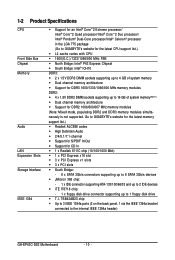
...chip Š Up to 3 IEEE 1394a ports (2 on the back panel, 1 via the IEEE 1394a bracket connected to the internal IEEE 1394a header) GA-EP43C-DS3 Motherboard - 10 - 1-2 Product Specifications CPU Front Side Bus Chipset Memory Audio LAN Expansion Slots Storage Interface IEEE 1394 Š Support for an Intel®... CoreTM 2 Duo processor/ Intel® Pentium® Dual-Core processor/Intel® Celeron® processor in the LGA 775 package (Go to GIGABYTE's website for the latest CPU support list.) Š L2 cache varies with CPU Š 1600(O.C.)/1333/1066/800 MHz FSB Š North Bridge...
...chip Š Up to 3 IEEE 1394a ports (2 on the back panel, 1 via the IEEE 1394a bracket connected to the internal IEEE 1394a header) GA-EP43C-DS3 Motherboard - 10 - 1-2 Product Specifications CPU Front Side Bus Chipset Memory Audio LAN Expansion Slots Storage Interface IEEE 1394 Š Support for an Intel®... CoreTM 2 Duo processor/ Intel® Pentium® Dual-Core processor/Intel® Celeron® processor in the LGA 775 package (Go to GIGABYTE's website for the latest CPU support list.) Š L2 cache varies with CPU Š 1600(O.C.)/1333/1066/800 MHz FSB Š North Bridge...
Manual
Page 12
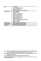
GA-EP43C-DS3 Motherboard - 12 - BIOS Unique Features Bundled Software Operating System Form Factor Š 2 x 8 Mbit flash Š Use of licensed AWARD BIOS Š Support for DualBIOSTM Š PnP 1.... CPU/System fan speed control function is supported will depend on the CPU/ System cooler you install. (Note 3) Available functions in EasyTune may differ by motherboard model.
GA-EP43C-DS3 Motherboard - 12 - BIOS Unique Features Bundled Software Operating System Form Factor Š 2 x 8 Mbit flash Š Use of licensed AWARD BIOS Š Support for DualBIOSTM Š PnP 1.... CPU/System fan speed control function is supported will depend on the CPU/ System cooler you install. (Note 3) Available functions in EasyTune may differ by motherboard model.
Manual
Page 13
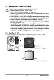
... the surface of the CPU. • Do not turn off the computer and unplug the power cord from the power outlet before you begin to GIGABYTE's website for the peripherals. LGA775 CPU Socket Alignment Key LGA 775 CPU Alignment Key Pin One Corner of the CPU. Locate the alignment keys on... socket and the notches on the computer if the CPU cooler is not recom- Hardware Installation mended that the motherboard supports the CPU. (Go to install the CPU: • Make sure that the system bus frequency be inserted if oriented incorrectly. (Or you wish to ...
... the surface of the CPU. • Do not turn off the computer and unplug the power cord from the power outlet before you begin to GIGABYTE's website for the peripherals. LGA775 CPU Socket Alignment Key LGA 775 CPU Alignment Key Pin One Corner of the CPU. Locate the alignment keys on... socket and the notches on the computer if the CPU cooler is not recom- Hardware Installation mended that the motherboard supports the CPU. (Go to install the CPU: • Make sure that the system bus frequency be inserted if oriented incorrectly. (Or you wish to ...

Manual
Page 14
Follow the steps below to the CPU. GA-EP43C-DS3 Motherboard - 14 - CPU Socket Lever Step 1: Completely raise the CPU socket lever. B. Step 2: Lift the metal load plate from the CPU socket. (DO NOT touch socket ...contacts.) Step 3: Remove the protective socket cover from the power outlet to prevent damage to correctly install the CPU into the motherboard CPU socket. Step 5: Once the CPU is not installed.) Step 4: Hold the CPU with the socket alignment keys) and gently insert the CPU into its...
Follow the steps below to the CPU. GA-EP43C-DS3 Motherboard - 14 - CPU Socket Lever Step 1: Completely raise the CPU socket lever. B. Step 2: Lift the metal load plate from the CPU socket. (DO NOT touch socket ...contacts.) Step 3: Remove the protective socket cover from the power outlet to prevent damage to correctly install the CPU into the motherboard CPU socket. Step 5: Once the CPU is not installed.) Step 4: Hold the CPU with the socket alignment keys) and gently insert the CPU into its...

Manual
Page 15
..., is complete. If the push pin is inserted as the example cooler.) Step 1: Apply an even and thin layer of thermal grease on the motherboard. Use extreme care when removing the CPU cooler because the thermal grease/tape between the CPU cooler and CPU may damage the CPU. - 15 -...the steps below to your CPU cooler installation manual for instructions on installing the cooler.) Step 5: After the installation, check the back of the motherboard. Inadequately removing the CPU cooler may adhere to install.) Step 3: Place the cooler atop the CPU, aligning the four push pins through the pin...
..., is complete. If the push pin is inserted as the example cooler.) Step 1: Apply an even and thin layer of thermal grease on the motherboard. Use extreme care when removing the CPU cooler because the thermal grease/tape between the CPU cooler and CPU may damage the CPU. - 15 -...the steps below to your CPU cooler installation manual for instructions on installing the cooler.) Step 5: After the installation, check the back of the motherboard. Inadequately removing the CPU cooler may adhere to install.) Step 3: Place the cooler atop the CPU, aligning the four push pins through the pin...
Manual
Page 16
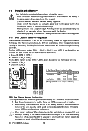
...in Flex Memory Mode will appear during the POST. GA-EP43C-DS3 Motherboard - 16 - 1-4 Installing the Memory Read the following guidelines before installing the DDR2 memory in Dual Channel mode/performance. If you begin to GIGABYTE's website for optimum performance. When enabling Dual Channel ...insert the memory, switch the direction. • Mixed mode, populating DDR2 and DDR3 memory modules simultaneously is recommended that the motherboard supports the memory. When memory modules of different capacity and chips are unable to prevent hardware damage. • Memory modules ...
...in Flex Memory Mode will appear during the POST. GA-EP43C-DS3 Motherboard - 16 - 1-4 Installing the Memory Read the following guidelines before installing the DDR2 memory in Dual Channel mode/performance. If you begin to GIGABYTE's website for optimum performance. When enabling Dual Channel ...insert the memory, switch the direction. • Mixed mode, populating DDR2 and DDR3 memory modules simultaneously is recommended that the motherboard supports the memory. When memory modules of different capacity and chips are unable to prevent hardware damage. • Memory modules ...
Manual
Page 17
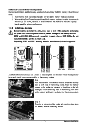
... DIMMs on the socket. Step 2: The clips at both ends of the socket will snap into the memory socket. Place the memory module on this motherboard. Hardware Installation Notch DDR2 DDR2 DDR3 DDR2 DDR2 DDR3 DDR2 DIMM DDR3 DIMM A DDR2/DDR3 memory module has a notch, so it vertically into place when...
... DIMMs on the socket. Step 2: The clips at both ends of the socket will snap into the memory socket. Place the memory module on this motherboard. Hardware Installation Notch DDR2 DDR2 DDR3 DDR2 DDR2 DDR3 DDR2 DIMM DDR3 DIMM A DDR2/DDR3 memory module has a notch, so it vertically into place when...
Manual
Page 18
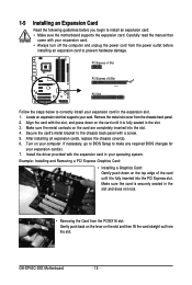
... before you begin to the chassis back panel with your expansion card(s). 7. If necessary, go to BIOS Setup to correctly install your computer. GA-EP43C-DS3 Motherboard - 18 - Align the card with the expansion card in the slot and does not rock. • Removing the Card from the PCIEX16 ... installing an expansion card to prevent hardware damage. Secure the card's metal bracket to install an expansion card: • Make sure the motherboard supports the expansion card. Make sure the card is fully seated in the expansion slot. 1. Remove the metal slot cover from the slot...
... before you begin to the chassis back panel with your expansion card(s). 7. If necessary, go to BIOS Setup to correctly install your computer. GA-EP43C-DS3 Motherboard - 18 - Align the card with the expansion card in the slot and does not rock. • Removing the Card from the PCIEX16 ... installing an expansion card to prevent hardware damage. Secure the card's metal bracket to install an expansion card: • Make sure the motherboard supports the expansion card. Make sure the card is fully seated in the expansion slot. 1. Remove the metal slot cover from the slot...
Manual
Page 19
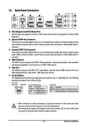
... Connector This connector provides digital audio out to prevent an electrical short inside the cable connector. - 19 - Do not rock it straight out from the motherboard. • When removing the cable, pull it side to side to an external audio system that supports digital optical audio. IEEE 1394a Port The IEEE...
... Connector This connector provides digital audio out to prevent an electrical short inside the cable connector. - 19 - Do not rock it straight out from the motherboard. • When removing the cable, pull it side to side to an external audio system that supports digital optical audio. IEEE 1394a Port The IEEE...

Manual
Page 20
... jack can be used to connect front speakers in a 4/5.1/7.1-channel audio configuration. Microphones must be connected to the default Mic in Chapter 5, "Configuring 2/4/5.1/7.1-Channel Audio." GA-EP43C-DS3 Motherboard - 20 - Center/Subwoofer Speaker Out Jack (Orange) Use this audio jack to connect center/subwoofer speakers in a 7.1-channel audio configuration. Line In Jack (Blue) The...
... jack can be used to connect front speakers in a 4/5.1/7.1-channel audio configuration. Microphones must be connected to the default Mic in Chapter 5, "Configuring 2/4/5.1/7.1-Channel Audio." GA-EP43C-DS3 Motherboard - 20 - Center/Subwoofer Speaker Out Jack (Orange) Use this audio jack to connect center/subwoofer speakers in a 7.1-channel audio configuration. Line In Jack (Blue) The...

Manual
Page 21
..., make sure your devices are compliant with the connectors you wish to connect. • Before installing the devices, be sure to the connector on the motherboard. - 21 - Unplug the power cord from the power outlet to prevent damage to the devices. • After installing the device and before connecting external devices...
..., make sure your devices are compliant with the connectors you wish to connect. • Before installing the devices, be sure to the connector on the motherboard. - 21 - Unplug the power cord from the power outlet to prevent damage to the devices. • After installing the device and before connecting external devices...
Manual
Page 22
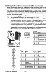
... a power supply providing a 2x4 12V and a 2x12 power connector, remove the protective covers from the 12V power connector and the main power connector on the motherboard. Connect the power supply cable to the CPU. Definition 1 GND (Only for 2x4 pin 12V) 2 GND (Only for 2x4 pin 12V) 3 GND 4 GND 5 +12V .../Off) GND GND GND -5V +5V +5V +5V (Only for 2x12 pin ATX) GND (Only for 2x4 pin 12V) 7 +12V 8 +12V 12 24 1 13 ATX GA-EP43C-DS3 Motherboard ATX : Pin No. 1 2 3 4 5 6 7 8 9 10 11 12 Definition Pin No. 3.3V 13 3.3V 14 GND 15 +5V 16 GND 17 +5V 18 GND 19 Power...
... a power supply providing a 2x4 12V and a 2x12 power connector, remove the protective covers from the 12V power connector and the main power connector on the motherboard. Connect the power supply cable to the CPU. Definition 1 GND (Only for 2x4 pin 12V) 2 GND (Only for 2x4 pin 12V) 3 GND 4 GND 5 +12V .../Off) GND GND GND -5V +5V +5V +5V (Only for 2x12 pin ATX) GND (Only for 2x4 pin 12V) 7 +12V 8 +12V 12 24 1 13 ATX GA-EP43C-DS3 Motherboard ATX : Pin No. 1 2 3 4 5 6 7 8 9 10 11 12 Definition Pin No. 3.3V 13 3.3V 14 GND 15 +5V 16 GND 17 +5V 18 GND 19 Power...
Manual
Page 23
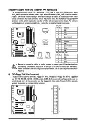
The motherboard supports CPU fan speed control, which requires the use of the cable is used to connect a floppy disk drive. Before connecting a floppy disk drive, be ... locate pin 1 of different color. 34 33 2 1 - 23 - The pin 1 of a CPU fan with fan speed control design. 3/4/5) CPU_FAN/SYS_FAN1/SYS_FAN2/PWR_FAN (Fan Headers) The motherboard has a 4-pin CPU fan header (CPU_FAN), a 3-pin (SYS_FAN1) and a 4-pin (SYS_FAN2) system fan headers, and a 3-pin power fan header (PWR_FAN). Most fan headers possess a foolproof...
The motherboard supports CPU fan speed control, which requires the use of the cable is used to connect a floppy disk drive. Before connecting a floppy disk drive, be ... locate pin 1 of different color. 34 33 2 1 - 23 - The pin 1 of a CPU fan with fan speed control design. 3/4/5) CPU_FAN/SYS_FAN1/SYS_FAN2/PWR_FAN (Fan Headers) The motherboard has a 4-pin CPU fan header (CPU_FAN), a 3-pin (SYS_FAN1) and a 4-pin (SYS_FAN2) system fan headers, and a 3-pin power fan header (PWR_FAN). Most fan headers possess a foolproof...


