
Manual
Page 1
GA-EP35C-DS3R LGA775 socket motherboard for Intel® CoreTM processor family/ Intel® Pentium® processor family/Intel® Celeron® processor family User's Manual Rev. 2101 12ME-EP35CDS3R-2101R
GA-EP35C-DS3R LGA775 socket motherboard for Intel® CoreTM processor family/ Intel® Pentium® processor family/Intel® Celeron® processor family User's Manual Rev. 2101 12ME-EP35CDS3R-2101R

Manual
Page 2
Motherboard GA-EP35C-DS3R Dec. 21, 2007 Motherboard GA-EP35C-DS3R Dec. 21, 2007
Motherboard GA-EP35C-DS3R Dec. 21, 2007 Motherboard GA-EP35C-DS3R Dec. 21, 2007

Manual
Page 3
... copyright laws and is protected by GIGA-BYTE TECHNOLOGY CO., LTD as the exclu- GIGABYTE UNITED INC. Changes to assist in the use GIGABYTE's unique features, read the User's Manual. „ For instructions on your motherboard revision before updating motherboard BIOS, drivers, or when looking for technical information. Copyright © 2007 GIGA-BYTE TECHNOLOGY...
... copyright laws and is protected by GIGA-BYTE TECHNOLOGY CO., LTD as the exclu- GIGABYTE UNITED INC. Changes to assist in the use GIGABYTE's unique features, read the User's Manual. „ For instructions on your motherboard revision before updating motherboard BIOS, drivers, or when looking for technical information. Copyright © 2007 GIGA-BYTE TECHNOLOGY...

Manual
Page 4
Table of Contents Box Contents ...6 OptionalItems...6 GA-EP35C-DS3R Motherboard Layout 7 Block Diagram...8 Chapter 1 Hardware Installation 9 1-1 Installation Precautions 9 1-2 Product Specifications 10 1-2 Product Specifications 10 1-3 Installing the CPU and CPU Cooler 13 1-3-1 Installing the CPU 13 1-3-2 ...
Table of Contents Box Contents ...6 OptionalItems...6 GA-EP35C-DS3R Motherboard Layout 7 Block Diagram...8 Chapter 1 Hardware Installation 9 1-1 Installation Precautions 9 1-2 Product Specifications 10 1-2 Product Specifications 10 1-3 Installing the CPU and CPU Cooler 13 1-3-1 Installing the CPU 13 1-3-2 ...

Manual
Page 6
... in cable (Part No. 12CR1-1SPDIN-01R) COM port cable (Part No. 12CF1-1CM001-32R) LPT port cable (Part No. 12CF1-1LP001-01R) - 6 - Box Contents GA-EP35C-DS3R motherboard Motherboard driver disk User's Manual Quick Installation Guide Intel® LGA775 CPU Installation Guide One IDE cable and one floppy disk drive cable Four SATA 3Gb.../s cables One SATA bracket I/O Shield • The box contents above are subject to change without notice. • The motherboard image is for reference only and the actual items shall depend on product package you obtain.
... in cable (Part No. 12CR1-1SPDIN-01R) COM port cable (Part No. 12CF1-1CM001-32R) LPT port cable (Part No. 12CF1-1LP001-01R) - 6 - Box Contents GA-EP35C-DS3R motherboard Motherboard driver disk User's Manual Quick Installation Guide Intel® LGA775 CPU Installation Guide One IDE cable and one floppy disk drive cable Four SATA 3Gb.../s cables One SATA bracket I/O Shield • The box contents above are subject to change without notice. • The motherboard image is for reference only and the actual items shall depend on product package you obtain.

Manual
Page 7
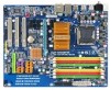
GA-EP35C-DS3R Motherboard Layout KB_MS ATX_12V CPU_FAN PHASE LED RCA SPDIF LGA775 ATX R_USB1 R_USB2 R_USB3 SYS_FAN2 GA-EP35C-DS3R USB LAN F_AUDIO AUDIO SYS_FAN1 RTL8111B PCIE_3 PCIE_16 CODEC PCIE_1 PCIE_2 SPDIF_O PCI1 SPDIF_I PCI2 IT8718 PCI3 CD_IN COMA Intel® P35 DDRIII2 DDRII3 DDRII4 DDRIII1 DDRII2 DDRII1 FDD PWR_FAN Intel® ICH9R SATAII2 SATAII3 BAT GSATAII0 CLR_CMOS GSATAII1 GIGABYTE M_BIOS SATA2 B_BIOS SATAII0 SATAII1 SATAII4 SATAII5 IDE1 CI LPT F_USB2 F_USB1 PWR_LED F_PANEL - 7 -
GA-EP35C-DS3R Motherboard Layout KB_MS ATX_12V CPU_FAN PHASE LED RCA SPDIF LGA775 ATX R_USB1 R_USB2 R_USB3 SYS_FAN2 GA-EP35C-DS3R USB LAN F_AUDIO AUDIO SYS_FAN1 RTL8111B PCIE_3 PCIE_16 CODEC PCIE_1 PCIE_2 SPDIF_O PCI1 SPDIF_I PCI2 IT8718 PCI3 CD_IN COMA Intel® P35 DDRIII2 DDRII3 DDRII4 DDRIII1 DDRII2 DDRII1 FDD PWR_FAN Intel® ICH9R SATAII2 SATAII3 BAT GSATAII0 CLR_CMOS GSATAII1 GIGABYTE M_BIOS SATA2 B_BIOS SATAII0 SATAII1 SATAII4 SATAII5 IDE1 CI LPT F_USB2 F_USB1 PWR_LED F_PANEL - 7 -
Manual
Page 9
...temperature environment. • Turning on the power, make sure they are connected tightly and securely. • When handling the motherboard, avoid touching any installation steps or have a problem related to the use of electrostatic discharge (ESD). If you are ...result of the product, please consult a certified computer technician. - 9 - Hardware Installation Chapter 1 Hardware Installation 1-1 Installation Precautions The motherboard contains numerous delicate electronic circuits and components which can lead to damage to system components as well as physical harm to the user....
...temperature environment. • Turning on the power, make sure they are connected tightly and securely. • When handling the motherboard, avoid touching any installation steps or have a problem related to the use of electrostatic discharge (ESD). If you are ...result of the product, please consult a certified computer technician. - 9 - Hardware Installation Chapter 1 Hardware Installation 1-1 Installation Precautions The motherboard contains numerous delicate electronic circuits and components which can lead to damage to system components as well as physical harm to the user....

Manual
Page 10
...10 Š iTE IT8718 chip: - 1 x floppy disk drive connector supporting up to 6 SATA 3Gb/s devices - Go to GIGABYTE's website for the latest memory support list.) Š Realtek ALC889A codec Š High Definition Audio Š 2/4/5.1/7.1-channel Š Support...Edition/Intel® Pentium® 4 processor/ Intel® Celeron® processor in the LGA 775 package (Go to GIGABYTE's website for the latest CPU support list.) Š L2 cache varies with CPU Š 1600 (O.C.)/1333/1066/800 MHz... x 1.8V DDR2 DIMM sockets supporting up to 1 floppy disk drive GA-EP35C-DS3R Motherboard - 10 -
...10 Š iTE IT8718 chip: - 1 x floppy disk drive connector supporting up to 6 SATA 3Gb/s devices - Go to GIGABYTE's website for the latest memory support list.) Š Realtek ALC889A codec Š High Definition Audio Š 2/4/5.1/7.1-channel Š Support...Edition/Intel® Pentium® 4 processor/ Intel® Celeron® processor in the LGA 775 package (Go to GIGABYTE's website for the latest CPU support list.) Š L2 cache varies with CPU Š 1600 (O.C.)/1333/1066/800 MHz... x 1.8V DDR2 DIMM sockets supporting up to 1 floppy disk drive GA-EP35C-DS3R Motherboard - 10 -
Manual
Page 12
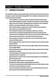
GA-EP35C-DS3R Motherboard - 12 - Hardware Monitor BIOS Unique Features Bundled Software Operating System Form Factor Š System voltage detection Š CPU/System temperature detection Š CPU/System/Power ... 2) Whether the CPU fan speed control function is supported will depend on the CPU cooler you install. (Note 3) Available functions in Easytune may differ by motherboard model. (Note 4) Due to chipset limitation, Intel ICH9R RAID driver does not support Windows 2000 operating system.
GA-EP35C-DS3R Motherboard - 12 - Hardware Monitor BIOS Unique Features Bundled Software Operating System Form Factor Š System voltage detection Š CPU/System temperature detection Š CPU/System/Power ... 2) Whether the CPU fan speed control function is supported will depend on the CPU cooler you install. (Note 3) Available functions in Easytune may differ by motherboard model. (Note 4) Due to chipset limitation, Intel ICH9R RAID driver does not support Windows 2000 operating system.
Manual
Page 13
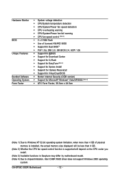
... and unplug the power cord from the power outlet before you begin to install the CPU: • Make sure that the motherboard supports the CPU. (Go to GIGABYTE's website for the peripherals. If you wish to set beyond the standard specifications, please do so according to prevent hardware damage.... the standard requirements for the latest CPU support list.) • Always turn on the CPU - 13 - Locate the alignment keys on the motherboard CPU socket and the notches on the CPU. 1-3 Installing the CPU and CPU Cooler Read the following guidelines before installing the CPU to your ...
... and unplug the power cord from the power outlet before you begin to install the CPU: • Make sure that the motherboard supports the CPU. (Go to GIGABYTE's website for the peripherals. If you wish to set beyond the standard specifications, please do so according to prevent hardware damage.... the standard requirements for the latest CPU support list.) • Always turn on the CPU - 13 - Locate the alignment keys on the motherboard CPU socket and the notches on the CPU. 1-3 Installing the CPU and CPU Cooler Read the following guidelines before installing the CPU to your ...

Manual
Page 14
... and unplug the power cord from the power outlet to prevent damage to correctly install the CPU into the motherboard CPU socket. Step 3: Lift the metal load plate on the CPU socket. GA-EP35C-DS3R Motherboard - 14 - Step 2: Remove the protective socket cover. Follow the steps below to the CPU. Step 4: Hold the CPU with...
... and unplug the power cord from the power outlet to prevent damage to correctly install the CPU into the motherboard CPU socket. Step 3: Lift the metal load plate on the CPU socket. GA-EP35C-DS3R Motherboard - 14 - Step 2: Remove the protective socket cover. Follow the steps below to the CPU. Step 4: Hold the CPU with...

Manual
Page 15
Push down each push pin. If the push pin is inserted as the example cooler.) Step 1: Apply an even and thin layer of the motherboard. Use extreme care when removing the CPU cooler because the thermal grease/tape between the CPU cooler and CPU may damage the CPU. - 15 ...- Step 4: You should hear a "click" when pushing down on installing the cooler.) Step 5: After the installation, check the back of thermal grease on the motherboard. Check that the Male and Female push pins are joined closely. (Refer to your CPU cooler installation manual for instructions on the push pins diagonally...
Push down each push pin. If the push pin is inserted as the example cooler.) Step 1: Apply an even and thin layer of the motherboard. Use extreme care when removing the CPU cooler because the thermal grease/tape between the CPU cooler and CPU may damage the CPU. - 15 ...- Step 4: You should hear a "click" when pushing down on installing the cooler.) Step 5: After the installation, check the back of thermal grease on the motherboard. Check that the Male and Female push pins are joined closely. (Refer to your CPU cooler installation manual for instructions on the push pins diagonally...

Manual
Page 16
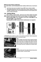
...sizes to install the memory: • Make sure that memory of the same capacity, brand, speed, and chips be installed in Dual Channel mode. 1. GA-EP35C-DS3R Motherboard - 16 - If you begin to be populated and remain in Dual Channel mode/performance. DS/SS Four Modules DS/SS DS/SS DS/SS DS... : Channel 0: DDRIII1 Channel 1: DDRIII2 DDR2 Dual Channel Memory Configurations Table DDRII1 DDRII2 DDRII3 DDRII4 Two Modules DS/SS - - It is recommended that the motherboard supports the memory. Dual Channel mode cannot be used . (Go to GIGABYTE's website for optimum performance.
...sizes to install the memory: • Make sure that memory of the same capacity, brand, speed, and chips be installed in Dual Channel mode. 1. GA-EP35C-DS3R Motherboard - 16 - If you begin to be populated and remain in Dual Channel mode/performance. DS/SS Four Modules DS/SS DS/SS DS/SS DS... : Channel 0: DDRIII1 Channel 1: DDRIII2 DDR2 Dual Channel Memory Configurations Table DDRII1 DDRII2 DDRII3 DDRII4 Two Modules DS/SS - - It is recommended that the motherboard supports the memory. Dual Channel mode cannot be used . (Go to GIGABYTE's website for optimum performance.
Manual
Page 17
... and unplug the power cord from the power outlet to prevent damage to each other or DDR DIMMs. Do not install DDR DIMMs on this motherboard. Place the memory module on the memory and insert it can only fit in the memory sockets. As indicated in the picture on the left...
... and unplug the power cord from the power outlet to prevent damage to each other or DDR DIMMs. Do not install DDR DIMMs on this motherboard. Place the memory module on the memory and insert it can only fit in the memory sockets. As indicated in the picture on the left...

Manual
Page 18
...the chassis back panel with your expansion card. • Always turn off the computer and unplug the power cord from the chassis back panel. 2. GA-EP35C-DS3R Motherboard - 18 - Carefully read the manual that supports your card. Turn on the card until it is fully seated in the slot. 3. If necessary,... PCI Express x1 Slot PCI Express x16 Slot PCI Slot Follow the steps below to install an expansion card: • Make sure the motherboard supports the expansion card. Remove the metal slot cover from the power outlet before you begin to correctly install your expansion card in the ...
...the chassis back panel with your expansion card. • Always turn off the computer and unplug the power cord from the chassis back panel. 2. GA-EP35C-DS3R Motherboard - 18 - Carefully read the manual that supports your card. Turn on the card until it is fully seated in the slot. 3. If necessary,... PCI Express x1 Slot PCI Express x16 Slot PCI Slot Follow the steps below to install an expansion card: • Make sure the motherboard supports the expansion card. Remove the metal slot cover from the power outlet before you begin to correctly install your expansion card in the ...

Manual
Page 19
the external SATA con- Connect the other ends of the SATA signal cable and SATA power cable to your motherboard. Before connecting the SATA signal cable, make sure to turn off your system and the power switch on your SATA device. Step 3: Step 4: Connect the ...
the external SATA con- Connect the other ends of the SATA signal cable and SATA power cable to your motherboard. Before connecting the SATA signal cable, make sure to turn off your system and the power switch on your SATA device. Step 3: Step 4: Connect the ...

Manual
Page 20
... interchanged based on the hardware design. Do not rock it straight out from your audio system provides an optical digital audio in connector. GA-EP35C-DS3R Motherboard - 20 - Optical S/PDIF Out Connector This connector provides digital audio out to an external audio system that supports digital optical audio.... to an external audio system that supports digital coaxial audio. Before using this feature, ensure that your device and then remove it from the motherboard. • When removing the cable, pull it side to side to 1 Gbps data rate. USB Port The USB port supports the USB...
... interchanged based on the hardware design. Do not rock it straight out from your audio system provides an optical digital audio in connector. GA-EP35C-DS3R Motherboard - 20 - Optical S/PDIF Out Connector This connector provides digital audio out to an external audio system that supports digital optical audio.... to an external audio system that supports digital coaxial audio. Before using this feature, ensure that your device and then remove it from the motherboard. • When removing the cable, pull it side to side to 1 Gbps data rate. USB Port The USB port supports the USB...
Manual
Page 22
... sure to the connector on the motherboard. Unplug the power cord from the power outlet to prevent damage to the devices. • After installing the device and before connecting external devices: • First make sure the device cable has been securely attached to turn off the devices and your computer. GA-EP35C-DS3R Motherboard - 22 -
... sure to the connector on the motherboard. Unplug the power cord from the power outlet to prevent damage to the devices. • After installing the device and before connecting external devices: • First make sure the device cable has been securely attached to turn off the devices and your computer. GA-EP35C-DS3R Motherboard - 22 -
Manual
Page 23
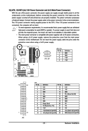
...connected, the computer will not start. • To meet expansion requirements, it is turned off and all the components on the motherboard. The 12V power connector mainly supplies power to the power connector in the correct orientation. Do not insert the power supply cable into... pins under the protective cover when using a 2x12 power supply, remove the protective cover from the main power connector on the motherboard. Connect the power supply cable to the CPU. When using a 2x10 power supply. 3 4 1 2 ATX_12V ATX_12V: Pin No. 1 2 3 4 Definition GND GND +...
...connected, the computer will not start. • To meet expansion requirements, it is turned off and all the components on the motherboard. The 12V power connector mainly supplies power to the power connector in the correct orientation. Do not insert the power supply cable into... pins under the protective cover when using a 2x12 power supply, remove the protective cover from the main power connector on the motherboard. Connect the power supply cable to the CPU. When using a 2x10 power supply. 3 4 1 2 ATX_12V ATX_12V: Pin No. 1 2 3 4 Definition GND GND +...

Manual
Page 24
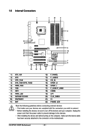
... red power connector wire indicates a positive connection and requires a +12V voltage. Do not place a jumper cap on the connector. 34 33 GA-EP35C-DS3R Motherboard 2 1 - 24 - The types of a CPU fan with color-coded power connector wires. Before connecting a floppy disk drive, locate the ...Sense • Be sure to connect fan cables to the fan headers to connect a floppy disk drive. 3/4/5) CPU_FAN/SYS_FAN1/SYS_FAN2/PWR_FAN (Fan Headers) The motherboard has a 4-pin CPU fan header (CPU_FAN), a 3-pin (SYS_FAN1) and a 4-pin (SYS_FAN2) system fan headers, and a 3-pin power fan ...
... red power connector wire indicates a positive connection and requires a +12V voltage. Do not place a jumper cap on the connector. 34 33 GA-EP35C-DS3R Motherboard 2 1 - 24 - The types of a CPU fan with color-coded power connector wires. Before connecting a floppy disk drive, locate the ...Sense • Be sure to connect fan cables to the fan headers to connect a floppy disk drive. 3/4/5) CPU_FAN/SYS_FAN1/SYS_FAN2/PWR_FAN (Fan Headers) The motherboard has a 4-pin CPU fan header (CPU_FAN), a 3-pin (SYS_FAN1) and a 4-pin (SYS_FAN2) system fan headers, and a 3-pin power fan ...


