
Manual
Page 1
GA-EP35-DS4 LGA775 socket motherboard for Intel® CoreTM processor family/ Intel® Pentium® processor family/Intel® Celeron® processor family User's Manual Rev. 2101 12ME-EP35DS4-2101R
GA-EP35-DS4 LGA775 socket motherboard for Intel® CoreTM processor family/ Intel® Pentium® processor family/Intel® Celeron® processor family User's Manual Rev. 2101 12ME-EP35DS4-2101R

Manual
Page 2
Motherboard GA-EP35-DS4 Dec. 21, 2007 Motherboard GA-EP35-DS4 Dec. 21, 2007
Motherboard GA-EP35-DS4 Dec. 21, 2007 Motherboard GA-EP35-DS4 Dec. 21, 2007
Manual
Page 3
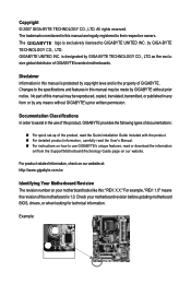
... means the revision of this manual is protected by any means without prior notice. Check your motherboard looks like this manual are legally registered to GIGABYTE UNITED INC. The trademarks mentioned in this : "REV: X.X." is exclusively licensed to their respective...at: http://www.gigabyte.com.tw Identifying Your Motherboard Revision The revision number on your motherboard revision before updating motherboard BIOS, drivers, or when looking for technical information. No part of the motherboard is the property of GIGABYTE branded motherboards. Example: Disclaimer ...
... means the revision of this manual is protected by any means without prior notice. Check your motherboard looks like this manual are legally registered to GIGABYTE UNITED INC. The trademarks mentioned in this : "REV: X.X." is exclusively licensed to their respective...at: http://www.gigabyte.com.tw Identifying Your Motherboard Revision The revision number on your motherboard revision before updating motherboard BIOS, drivers, or when looking for technical information. No part of the motherboard is the property of GIGABYTE branded motherboards. Example: Disclaimer ...

Manual
Page 4
Table of Contents Box Contents ...6 OptionalItems...6 GA-EP35-DS4 Motherboard Layout 7 Block Diagram...8 Chapter 1 Hardware Installation 9 1-1 Installation Precautions 9 1-2 Product Specifications 10 1-3 Installing the CPU and CPU Cooler 13 1-3-1 Installing the CPU 13 1-3-2 Installing the CPU ...
Table of Contents Box Contents ...6 OptionalItems...6 GA-EP35-DS4 Motherboard Layout 7 Block Diagram...8 Chapter 1 Hardware Installation 9 1-1 Installation Precautions 9 1-2 Product Specifications 10 1-3 Installing the CPU and CPU Cooler 13 1-3-1 Installing the CPU 13 1-3-2 Installing the CPU ...

Manual
Page 6
Box Contents GA-EP35-DS4 motherboard Motherboard driver disk User's Manual Quick Installation Guide Intel® LGA775 CPU Installation Guide One IDE cable and one floppy disk drive cable Four SATA 3Gb/s cables One SATA bracket I/O Shield • The box contents above are subject to change without notice. • The motherboard image is for reference only and...
Box Contents GA-EP35-DS4 motherboard Motherboard driver disk User's Manual Quick Installation Guide Intel® LGA775 CPU Installation Guide One IDE cable and one floppy disk drive cable Four SATA 3Gb/s cables One SATA bracket I/O Shield • The box contents above are subject to change without notice. • The motherboard image is for reference only and...

Manual
Page 7
GA-EP35-DS4 Motherboard Layout RCA SPDIF-1 KB_MS SYS_FAN1 USB ATX_12V_2X LGA775 PHASE LED PWR_FAN PCIE_12V ATX 1394_2 1394_1 USB USB GA-EP35-DS4 LAN USB CPU_FAN F_AUDIO AUDIO PCIE_1 Intel® P35 RTL8111B PCIE_16_1 NB_FAN FDD DDRII1 DDRII2 DDRII3 DDRII4 CODEC PCIE_2 PCIE_3 SPDIF_O IT8718 CD_IN PCI1 PCI2 SPDIF_IN BP_BIOS MAIN_BIOS CLR_CMOS BAT PCIE_16_2 Intel® ICH9R TSB43AB23 CI SATAII4 SATAII5 SYS_FAN2 SATAII0 SATAII1 IDE SATAII2 SATAII3 GIGABYTE SATA2 GSATAII0 GSATAII1 F_USB2 F_USB1 COMA LPT F1_1394 PWR_LED F_PANEL - 7 -
GA-EP35-DS4 Motherboard Layout RCA SPDIF-1 KB_MS SYS_FAN1 USB ATX_12V_2X LGA775 PHASE LED PWR_FAN PCIE_12V ATX 1394_2 1394_1 USB USB GA-EP35-DS4 LAN USB CPU_FAN F_AUDIO AUDIO PCIE_1 Intel® P35 RTL8111B PCIE_16_1 NB_FAN FDD DDRII1 DDRII2 DDRII3 DDRII4 CODEC PCIE_2 PCIE_3 SPDIF_O IT8718 CD_IN PCI1 PCI2 SPDIF_IN BP_BIOS MAIN_BIOS CLR_CMOS BAT PCIE_16_2 Intel® ICH9R TSB43AB23 CI SATAII4 SATAII5 SYS_FAN2 SATAII0 SATAII1 IDE SATAII2 SATAII3 GIGABYTE SATA2 GSATAII0 GSATAII1 F_USB2 F_USB1 COMA LPT F1_1394 PWR_LED F_PANEL - 7 -

Manual
Page 9
... dry and first touch a metal object to eliminate static electricity. • Prior to installing the motherboard, please have a problem related to the motherboard, do not remove or break motherboard S/N (Serial Number) sticker or warranty sticker provided by your hardware components are connected. • To...of the product, please consult a certified computer technician. - 9 - If you are connected tightly and securely. • When handling the motherboard, avoid touching any installation steps or have it on top of an antistatic pad or within the computer casing. • Do not place...
... dry and first touch a metal object to eliminate static electricity. • Prior to installing the motherboard, please have a problem related to the motherboard, do not remove or break motherboard S/N (Serial Number) sticker or warranty sticker provided by your hardware components are connected. • To...of the product, please consult a certified computer technician. - 9 - If you are connected tightly and securely. • When handling the motherboard, avoid touching any installation steps or have it on top of an antistatic pad or within the computer casing. • Do not place...

Manual
Page 10
...Intel® Pentium® 4 processor Extreme Edition/Intel® Pentium® 4 processor/ Intel® Celeron® processor in the LGA 775 package (Go to GIGABYTE's website for the latest CPU support list.) Š L2 cache varies with the PCIE_16_2 slot) (Note 2) Š 2 x PCI slots Š South ... Š Dual channel memory architecture Š Support for DDR2 1200 (O.C.)/1066/800/667 MHz memory modules (Go to the internal IEEE 1394 header) GA-EP35-DS4 Motherboard - 10 - the PCIE_16_2 supports x4.) Š 3 x PCI Express x1 slots (share with CPU Š 1600 (O.C.)/1333/1066/800 MHz ...
...Intel® Pentium® 4 processor Extreme Edition/Intel® Pentium® 4 processor/ Intel® Celeron® processor in the LGA 775 package (Go to GIGABYTE's website for the latest CPU support list.) Š L2 cache varies with the PCIE_16_2 slot) (Note 2) Š 2 x PCI slots Š South ... Š Dual channel memory architecture Š Support for DDR2 1200 (O.C.)/1066/800/667 MHz memory modules (Go to the internal IEEE 1394 header) GA-EP35-DS4 Motherboard - 10 - the PCIE_16_2 supports x4.) Š 3 x PCI Express x1 slots (share with CPU Š 1600 (O.C.)/1333/1066/800 MHz ...

Manual
Page 12
... BIOS Setup (CPU/DDR2/PCIe) allow you install. (Note 4) Available functions in Easytune may differ by 0.05V to 1.55V with 0.05V increment - GA-EP35-DS4 Motherboard - 12 - Increase DDR2 voltage by motherboard model. (Note 5) The adjustable CPU voltage range depends on the CPU cooler you to: - Adjust PCI Express frequency from 100 MHz to 700...
... BIOS Setup (CPU/DDR2/PCIe) allow you install. (Note 4) Available functions in Easytune may differ by 0.05V to 1.55V with 0.05V increment - GA-EP35-DS4 Motherboard - 12 - Increase DDR2 voltage by motherboard model. (Note 5) The adjustable CPU voltage range depends on the CPU cooler you to: - Adjust PCI Express frequency from 100 MHz to 700...

Manual
Page 13
... on the CPU socket.) • Apply an even and thin layer of thermal grease on the surface of the CPU. mended that the motherboard supports the CPU. (Go to GIGABYTE's website for the latest CPU support list.) • Always turn off the computer and unplug the power cord from the power outlet... of the CPU. • Do not turn on the computer if the CPU cooler is not recom- Hardware Installation Locate the alignment keys on the motherboard CPU socket and the notches on the CPU - 13 - If you may occur. • Set the CPU host frequency in accordance with the CPU ...
... on the CPU socket.) • Apply an even and thin layer of thermal grease on the surface of the CPU. mended that the motherboard supports the CPU. (Go to GIGABYTE's website for the latest CPU support list.) • Always turn off the computer and unplug the power cord from the power outlet... of the CPU. • Do not turn on the computer if the CPU cooler is not recom- Hardware Installation Locate the alignment keys on the motherboard CPU socket and the notches on the CPU - 13 - If you may occur. • Set the CPU host frequency in accordance with the CPU ...

Manual
Page 14
... one marking (triangle) with the pin one corner of the CPU socket (or you may align the CPU notches with your thumb and index fingers. GA-EP35-DS4 Motherboard - 14 - Step 2: Remove the protective socket cover. Step 4: Hold the CPU with the socket alignment keys) and gently insert the CPU into its locked ... sure to turn off the computer and unplug the power cord from the power outlet to prevent damage to correctly install the CPU into the motherboard CPU socket. Step 3: Lift the metal load plate on the CPU socket. Follow the steps below to the CPU. Step 5: Once the CPU is ...
... one marking (triangle) with the pin one corner of the CPU socket (or you may align the CPU notches with your thumb and index fingers. GA-EP35-DS4 Motherboard - 14 - Step 2: Remove the protective socket cover. Step 4: Hold the CPU with the socket alignment keys) and gently insert the CPU into its locked ... sure to turn off the computer and unplug the power cord from the power outlet to prevent damage to correctly install the CPU into the motherboard CPU socket. Step 3: Lift the metal load plate on the CPU socket. Follow the steps below to the CPU. Step 5: Once the CPU is ...

Manual
Page 15
... Place the cooler atop the CPU, aligning the four push pins through the pin holes on the motherboard. Inadequately removing the CPU cooler may adhere to the CPU fan header (CPU_FAN) on the motherboard. Direction of the Arrow Sign on the Male Push Pin Male Push Pin The Top of Female Push...pin. (Turning the push pin along the direction of the installed CPU. Push down each push pin. Step 6: Finally, attach the power connector of the motherboard. Use extreme care when removing the CPU cooler because the thermal grease/tape between the CPU cooler and CPU may damage the CPU. - 15 - Check...
... Place the cooler atop the CPU, aligning the four push pins through the pin holes on the motherboard. Inadequately removing the CPU cooler may adhere to the CPU fan header (CPU_FAN) on the motherboard. Direction of the Arrow Sign on the Male Push Pin Male Push Pin The Top of Female Push...pin. (Turning the push pin along the direction of the installed CPU. Push down each push pin. Step 6: Finally, attach the power connector of the motherboard. Use extreme care when removing the CPU cooler because the thermal grease/tape between the CPU cooler and CPU may damage the CPU. - 15 - Check...

Manual
Page 16
...the same capacity, brand, speed, and chips be used . (Go to prevent hardware damage. • Memory modules have a foolproof design. GA-EP35-DS4 Motherboard - 16 - It is recommended that memory of the same capacity, brand, speed, and chips be installed in only one DDR2 memory module...=Double-Sided, "- -"=No Memory) DDRII1 DDRII2 DDRII3 DDRII4 Due to chipset limitation, read the following guidelines before installing the memory to GIGABYTE's website for optimum performance. A memory module can be used and installed in the same colored DDR2 sockets for the latest memory support ...
...the same capacity, brand, speed, and chips be used . (Go to prevent hardware damage. • Memory modules have a foolproof design. GA-EP35-DS4 Motherboard - 16 - It is recommended that memory of the same capacity, brand, speed, and chips be installed in only one DDR2 memory module...=Double-Sided, "- -"=No Memory) DDRII1 DDRII2 DDRII3 DDRII4 Due to chipset limitation, read the following guidelines before installing the memory to GIGABYTE's website for optimum performance. A memory module can be used and installed in the same colored DDR2 sockets for the latest memory support ...

Manual
Page 17
.... Spread the retaining clips at both ends of the memory module. Step 1: Note the orientation of the memory socket. Place the memory module on this motherboard. Notch DDR2 DIMM A DDR2 memory module has a notch, so it vertically into place when the memory module is securely inserted. - 17 - Follow the steps below...
.... Spread the retaining clips at both ends of the memory module. Step 1: Note the orientation of the memory socket. Place the memory module on this motherboard. Notch DDR2 DIMM A DDR2 memory module has a notch, so it vertically into place when the memory module is securely inserted. - 17 - Follow the steps below...
Manual
Page 18
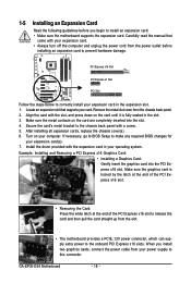
...Read the following guidelines before installing an expansion card to install an expansion card: • Make sure the motherboard supports the expansion card. Align the card with a screw. 5. Carefully read the manual that supports your computer... Gently insert the graphics card into the slot. 4. Remove the metal slot cover from the slot. • The motherboard provides a PCIE_12V power connector, which can supply extra power to the onboard PCI Express x16 slots. Secure the card's...7. Make sure the graphics card is fully seated in the slot. 3. GA-EP35-DS4 Motherboard - 18 -
...Read the following guidelines before installing an expansion card to install an expansion card: • Make sure the motherboard supports the expansion card. Align the card with a screw. 5. Carefully read the manual that supports your computer... Gently insert the graphics card into the slot. 4. Remove the metal slot cover from the slot. • The motherboard provides a PCIE_12V power connector, which can supply extra power to the onboard PCI Express x16 slots. Secure the card's...7. Make sure the graphics card is fully seated in the slot. 3. GA-EP35-DS4 Motherboard - 18 -

Manual
Page 19
... to your SATA device. nector on the bracket. 1-6 Installing the SATA Bracket The SATA bracket allows you only need to the SATA port on your motherboard. Step 3: Step 4: Connect the power Plug one SATA power cable. Connect the other ends of the cable from the bracket to connect the SATA signal...
... to your SATA device. nector on the bracket. 1-6 Installing the SATA Bracket The SATA bracket allows you only need to the SATA port on your motherboard. Step 3: Step 4: Connect the power Plug one SATA power cable. Connect the other ends of the cable from the bracket to connect the SATA signal...

Manual
Page 20
...receiving is occurring • When removing the cable connected to prevent an electrical short inside the cable connector. * The positions of the LAN port LEDs. GA-EP35-DS4 Motherboard - 20 - 1-7 Back Panel Connectors * PS/2 Keyboard and PS/2 Mouse Port Use the upper port (green) to connect a PS/2 mouse and... the lower port (purple) to 1 Gbps data rate. Before using this feature, ensure that your device and then remove it from the motherboard. • When removing the cable, pull it side to side to a back panel connector, first remove the cable from your audio system provides...
...receiving is occurring • When removing the cable connected to prevent an electrical short inside the cable connector. * The positions of the LAN port LEDs. GA-EP35-DS4 Motherboard - 20 - 1-7 Back Panel Connectors * PS/2 Keyboard and PS/2 Mouse Port Use the upper port (green) to connect a PS/2 mouse and... the lower port (purple) to 1 Gbps data rate. Before using this feature, ensure that your device and then remove it from the motherboard. • When removing the cable, pull it side to side to a back panel connector, first remove the cable from your audio system provides...

Manual
Page 22
... devices and your devices are compliant with the connectors you wish to connect. • Before installing the devices, be sure to the connector on the motherboard. GA-EP35-DS4 Motherboard - 22 -
... devices and your devices are compliant with the connectors you wish to connect. • Before installing the devices, be sure to the connector on the motherboard. GA-EP35-DS4 Motherboard - 22 -

Manual
Page 23
...when using an Intel Extreme Edition CPU (130W). • To meet expansion requirements, it is turned off and all the components on the motherboard. Before connecting the power connector, first make sure the power supply is recommended that a power supply that does not provide the required power,... a power supply providing a 2x4 12V and a 2x12 power connector, remove the protective covers from the 12V power connector and the main power connector on the motherboard. Definition 1 GND(Only for 2x4 pin 12V) 2 GND (Only for 2x4 pin 12V) 3 GND 4 GND 5 +12V (Only for 2x4 pin 12V) 6...
...when using an Intel Extreme Edition CPU (130W). • To meet expansion requirements, it is turned off and all the components on the motherboard. Before connecting the power connector, first make sure the power supply is recommended that a power supply that does not provide the required power,... a power supply providing a 2x4 12V and a 2x12 power connector, remove the protective covers from the 12V power connector and the main power connector on the motherboard. Definition 1 GND(Only for 2x4 pin 12V) 2 GND (Only for 2x4 pin 12V) 3 GND 4 GND 5 +12V (Only for 2x4 pin 12V) 6...

Manual
Page 24
Definition 1 NC 2 GND 3 GND 4 +12V 4) PHASE LED The number of lighted LEDs. GA-EP35-DS4 Motherboard - 24 - Failure to do so may lead to the PCI Express x16 slots on the motherboard. 3) PCIE_12V (Power Connector) This power connector can supply extra power to an unstable system. 1 PIin No. The higher the CPU loading, the more the number of lighted LEDs indicates the CPU loading. Connect the power supply cable to this connector when using two graphics cards.
Definition 1 NC 2 GND 3 GND 4 +12V 4) PHASE LED The number of lighted LEDs. GA-EP35-DS4 Motherboard - 24 - Failure to do so may lead to the PCI Express x16 slots on the motherboard. 3) PCIE_12V (Power Connector) This power connector can supply extra power to an unstable system. 1 PIin No. The higher the CPU loading, the more the number of lighted LEDs indicates the CPU loading. Connect the power supply cable to this connector when using two graphics cards.


