Manual
Page 1
GA-EP35-DS3L/ GA-EP35-S3L LGA775 socket motherboard for Intel® CoreTM processor family/ Intel® Pentium® processor family/Intel® Celeron® processor family User's Manual Rev. 1002 12ME-EP35DS3L-1002R
GA-EP35-DS3L/ GA-EP35-S3L LGA775 socket motherboard for Intel® CoreTM processor family/ Intel® Pentium® processor family/Intel® Celeron® processor family User's Manual Rev. 1002 12ME-EP35DS3L-1002R

Manual
Page 2
Motherboard GA-EP35-DS3L/GA-EP35-S3L Feb. 1, 2008 Motherboard GA-EP35-DS3L/ GA-EP35-S3L Feb. 1, 2008
Motherboard GA-EP35-DS3L/GA-EP35-S3L Feb. 1, 2008 Motherboard GA-EP35-DS3L/ GA-EP35-S3L Feb. 1, 2008
Manual
Page 3
...may be reproduced, copied, translated, transmitted, or published in the use GIGABYTE's unique features, read the User's Manual. „ For instructions on your motherboard revision before updating motherboard BIOS, drivers, or when looking for technical information. Changes to their ...read or download the information on/from the Support\Motherboard\Technology Guide page on our website. sive global distributor of GIGABYTE. All rights reserved. GIGABYTE UNITED INC. Check your motherboard looks like this product, GIGABYTE provides the following types of documentations: „ For...
...may be reproduced, copied, translated, transmitted, or published in the use GIGABYTE's unique features, read the User's Manual. „ For instructions on your motherboard revision before updating motherboard BIOS, drivers, or when looking for technical information. Changes to their ...read or download the information on/from the Support\Motherboard\Technology Guide page on our website. sive global distributor of GIGABYTE. All rights reserved. GIGABYTE UNITED INC. Check your motherboard looks like this product, GIGABYTE provides the following types of documentations: „ For...

Manual
Page 4
Table of Contents Box Contents ...6 OptionalItems...6 GA-EP35-DS3L/S3L Motherboard Layout 7 Block Diagram...8 Chapter 1 Hardware Installation 9 1-1 Installation Precautions 9 1-2 Product Specifications 10 1-3 Installing the CPU and CPU Cooler 13 1-3-1 Installing the CPU 13 1-3-2 Installing the CPU ...
Table of Contents Box Contents ...6 OptionalItems...6 GA-EP35-DS3L/S3L Motherboard Layout 7 Block Diagram...8 Chapter 1 Hardware Installation 9 1-1 Installation Precautions 9 1-2 Product Specifications 10 1-3 Installing the CPU and CPU Cooler 13 1-3-1 Installing the CPU 13 1-3-2 Installing the CPU ...

Manual
Page 6
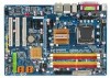
The box contents are for reference only. Box Contents GA-EP35-DS3L or GA-EP35-S3L motherboard Motherboard driver disk User's Manual Quick Installation Guide Intel® LGA775 CPU Installation Guide One IDE cable and one floppy disk drive cable Two SATA 3Gb.../s cables I/O Shield • The box contents above are subject to change without notice. • The motherboard image is for reference only and the ...
The box contents are for reference only. Box Contents GA-EP35-DS3L or GA-EP35-S3L motherboard Motherboard driver disk User's Manual Quick Installation Guide Intel® LGA775 CPU Installation Guide One IDE cable and one floppy disk drive cable Two SATA 3Gb.../s cables I/O Shield • The box contents above are subject to change without notice. • The motherboard image is for reference only and the ...
Manual
Page 7
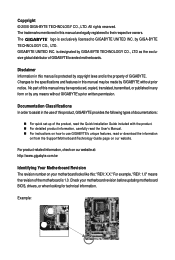
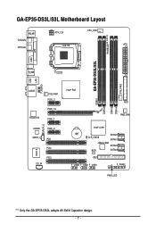
GA-EP35-DS3L/S3L Motherboard Layout KB_MS ATX_12V CPU_FAN COAXIAL OPTICAL LGA775 ATX PHASELED COM LPT DDRII1 GA-EP35-DS3L/S3L R_USB SYS_FAN2 USB LAN F_AUDIO AUDIO SYS_FAN1 PCIE_3 RTL8111B PCIE_16 PCIE_1 SPDIF_O CODEC PCIE_2 SPDIF_I PCI1 PCI2 IT8718 PCI3 CD_IN Intel® P35 FDD DDRII3 DDRII4 DDRII2 PWR_FAN Intel® ICH9 BAT CLR_CMOS SATAII0 SATAII1 JMicron 368 SATAII4 BIOS SATAII5 IDE1 F_USB3 F_USB2 F_USB1 CI F_PANEL PWR_LED "*" Only the GA-EP35-DS3L adopts All-Solid Capacitor design. - 7 -
GA-EP35-DS3L/S3L Motherboard Layout KB_MS ATX_12V CPU_FAN COAXIAL OPTICAL LGA775 ATX PHASELED COM LPT DDRII1 GA-EP35-DS3L/S3L R_USB SYS_FAN2 USB LAN F_AUDIO AUDIO SYS_FAN1 PCIE_3 RTL8111B PCIE_16 PCIE_1 SPDIF_O CODEC PCIE_2 SPDIF_I PCI1 PCI2 IT8718 PCI3 CD_IN Intel® P35 FDD DDRII3 DDRII4 DDRII2 PWR_FAN Intel® ICH9 BAT CLR_CMOS SATAII0 SATAII1 JMicron 368 SATAII4 BIOS SATAII5 IDE1 F_USB3 F_USB2 F_USB1 CI F_PANEL PWR_LED "*" Only the GA-EP35-DS3L adopts All-Solid Capacitor design. - 7 -

Manual
Page 9
...to system components as well as physical harm to the user. • If you are connected tightly and securely. • When handling the motherboard, avoid touching any installation steps or have it on top of an antistatic pad or within the computer casing. • Do not place the...8226; Before using the product, please verify that all cables and power connectors of your hardware components are connected. • To prevent damage to the motherboard, do not allow screws to come in a high-temperature environment. • Turning on the power, make sure they are uncertain about any metal ...
...to system components as well as physical harm to the user. • If you are connected tightly and securely. • When handling the motherboard, avoid touching any installation steps or have it on top of an antistatic pad or within the computer casing. • Do not place the...8226; Before using the product, please verify that all cables and power connectors of your hardware components are connected. • To prevent damage to the motherboard, do not allow screws to come in a high-temperature environment. • Turning on the power, make sure they are uncertain about any metal ...

Manual
Page 10
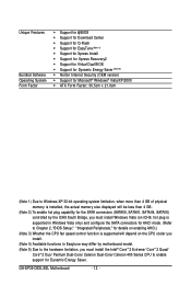
GA-EP35-DS3L/S3L Motherboard - 10 - 1-2 Product Specifications CPU Front Side Bus Chipset Memory Audio LAN...Extreme Edition/Intel® Pentium® 4 processor/ Intel® Celeron® processor in the LGA 775 package (Go to GIGABYTE's website for the latest CPU support list.) Š L2 cache varies with CPU Š 1333/1066/800 MHz FSB &#... (Note 1) Š Dual channel memory architecture Š Support for DDR2 1066/800/667 MHz memory modules (Go to GIGABYTE's website for the latest memory support list.) Š Realtek ALC888 codec Š High Definition Audio Š 2/4/5.1/7.1-channel &#...
GA-EP35-DS3L/S3L Motherboard - 10 - 1-2 Product Specifications CPU Front Side Bus Chipset Memory Audio LAN...Extreme Edition/Intel® Pentium® 4 processor/ Intel® Celeron® processor in the LGA 775 package (Go to GIGABYTE's website for the latest CPU support list.) Š L2 cache varies with CPU Š 1333/1066/800 MHz FSB &#... (Note 1) Š Dual channel memory architecture Š Support for DDR2 1066/800/667 MHz memory modules (Go to GIGABYTE's website for the latest memory support list.) Š Realtek ALC888 codec Š High Definition Audio Š 2/4/5.1/7.1-channel &#...
Manual
Page 12
... CPU cooler you install. (Note 4) Available functions in Easytune may differ by motherboard model. (Note 5) Due to the hardware limitation, you must install the Intel® CoreTM 2 Extreme/ CoreTM 2 Quad/ CoreTM 2 Duo/ Pentium Dual-Core/ Celeron Dual-Core/ Celeron 400 Series CPU to enable support for Dynamic Energy Saver. GA-EP35-DS3L/S3L Motherboard - 12 -
... CPU cooler you install. (Note 4) Available functions in Easytune may differ by motherboard model. (Note 5) Due to the hardware limitation, you must install the Intel® CoreTM 2 Extreme/ CoreTM 2 Quad/ CoreTM 2 Duo/ Pentium Dual-Core/ Celeron Dual-Core/ Celeron 400 Series CPU to enable support for Dynamic Energy Saver. GA-EP35-DS3L/S3L Motherboard - 12 -
Manual
Page 13
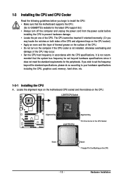
Locate the alignment keys on the motherboard CPU socket and the notches on the CPU - 13 - 1-3 Installing the CPU and CPU Cooler Read the following guidelines before installing the CPU to your ... the CPU cooler is not recom- LGA775 CPU Socket Alignment Key LGA 775 CPU Alignment Key Pin One Corner of the CPU. mended that the motherboard supports the CPU. (Go to GIGABYTE's website for the peripherals.
Locate the alignment keys on the motherboard CPU socket and the notches on the CPU - 13 - 1-3 Installing the CPU and CPU Cooler Read the following guidelines before installing the CPU to your ... the CPU cooler is not recom- LGA775 CPU Socket Alignment Key LGA 775 CPU Alignment Key Pin One Corner of the CPU. mended that the motherboard supports the CPU. (Go to GIGABYTE's website for the peripherals.

Manual
Page 14
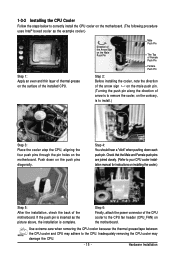
... sure to turn off the computer and unplug the power cord from the power outlet to prevent damage to correctly install the CPU into the motherboard CPU socket. Step 3: Lift the metal load plate on the CPU socket. Step 4: Hold the CPU with the socket alignment keys) and gently insert the... raise the CPU socket lever. Step 5: Once the CPU is properly inserted, replace the load plate and push the CPU socket lever back into position. GA-EP35-DS3L/S3L Motherboard - 14 - B.
... sure to turn off the computer and unplug the power cord from the power outlet to prevent damage to correctly install the CPU into the motherboard CPU socket. Step 3: Lift the metal load plate on the CPU socket. Step 4: Hold the CPU with the socket alignment keys) and gently insert the... raise the CPU socket lever. Step 5: Once the CPU is properly inserted, replace the load plate and push the CPU socket lever back into position. GA-EP35-DS3L/S3L Motherboard - 14 - B.
Manual
Page 15
... pins are joined closely. (Refer to install.) Step 3: Place the cooler atop the CPU, aligning the four push pins through the pin holes on the motherboard. Push down each push pin. 1-3-2 Installing the CPU Cooler Follow the steps below to the CPU fan header (CPU_FAN) on the... Installation Step 6: Finally, attach the power connector of the CPU cooler to correctly install the CPU cooler on the motherboard. (The following procedure uses Intel® boxed cooler as the picture above, the installation is to your CPU cooler installation manual for instructions on installing ...
... pins are joined closely. (Refer to install.) Step 3: Place the cooler atop the CPU, aligning the four push pins through the pin holes on the motherboard. Push down each push pin. 1-3-2 Installing the CPU Cooler Follow the steps below to the CPU fan header (CPU_FAN) on the... Installation Step 6: Finally, attach the power connector of the CPU cooler to correctly install the CPU cooler on the motherboard. (The following procedure uses Intel® boxed cooler as the picture above, the installation is to your CPU cooler installation manual for instructions on installing ...
Manual
Page 16
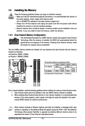
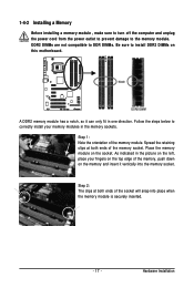
...the power cord from the power outlet before installing the memory to install the memory: • Make sure that memory of the memory. GA-EP35-DS3L/S3L Motherboard - 16 - Four Modules DS/SS DS/SS DS/SS DDRII4 - 1-4 Installing the Memory Read the following guidelines before installing the ... be enabled if only one direction. Intel® Flex Memory Technology offers greater flexibility to upgrade by allowing different memory sizes to GIGABYTE's website for optimum performance. When enabling Dual Channel mode with two or four memory modules, it is installed, the BIOS will ...
...the power cord from the power outlet before installing the memory to install the memory: • Make sure that memory of the memory. GA-EP35-DS3L/S3L Motherboard - 16 - Four Modules DS/SS DS/SS DS/SS DDRII4 - 1-4 Installing the Memory Read the following guidelines before installing the ... be enabled if only one direction. Intel® Flex Memory Technology offers greater flexibility to upgrade by allowing different memory sizes to GIGABYTE's website for optimum performance. When enabling Dual Channel mode with two or four memory modules, it is installed, the BIOS will ...
Manual
Page 17
... , make sure to turn off the computer and unplug the power cord from the power outlet to prevent damage to install DDR2 DIMMs on this motherboard. Follow the steps below to correctly install your fingers on the top edge of the memory socket.
... , make sure to turn off the computer and unplug the power cord from the power outlet to prevent damage to install DDR2 DIMMs on this motherboard. Follow the steps below to correctly install your fingers on the top edge of the memory socket.

Manual
Page 18
... the steps below to correctly install your expansion card. • Always turn off the computer and unplug the power cord from the chassis back panel. 2. GA-EP35-DS3L/S3L Motherboard - 18 - After installing all expansion cards, replace the chassis cover(s). 6. Example: Installing and Removing a PCI Express x16 Graphics Card: • Installing a Graphics Card: Gently.... 4. Align the card with the expansion card in the slot. 3. If necessary, go to BIOS Setup to install an expansion card: • Make sure the motherboard supports the expansion card.
... the steps below to correctly install your expansion card. • Always turn off the computer and unplug the power cord from the chassis back panel. 2. GA-EP35-DS3L/S3L Motherboard - 18 - After installing all expansion cards, replace the chassis cover(s). 6. Example: Installing and Removing a PCI Express x16 Graphics Card: • Installing a Graphics Card: Gently.... 4. Align the card with the expansion card in the slot. 3. If necessary, go to BIOS Setup to install an expansion card: • Make sure the motherboard supports the expansion card.

Manual
Page 19
... is occurring • When removing the cable connected to a back panel connector, first remove the cable from your device and then remove it from the motherboard. • When removing the cable, pull it side to side to an external audio system that your audio system provides an optical digital audio in...
... is occurring • When removing the cable connected to a back panel connector, first remove the cable from your device and then remove it from the motherboard. • When removing the cable, pull it side to side to an external audio system that your audio system provides an optical digital audio in...
Manual
Page 20
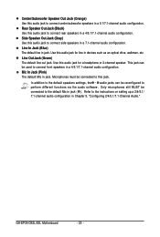
... configuration. In addition to the default speakers settings, the ~ audio jacks can be connected to the instructions on setting up a 2/4/5.1/ 7.1-channel audio configuration in jack. GA-EP35-DS3L/S3L Motherboard - 20 - Use this audio jack for a headphone or 2-channel speaker. Use this audio jack to connect center/subwoofer speakers in jack ( ). This jack can...
... configuration. In addition to the default speakers settings, the ~ audio jacks can be connected to the instructions on setting up a 2/4/5.1/ 7.1-channel audio configuration in jack. GA-EP35-DS3L/S3L Motherboard - 20 - Use this audio jack for a headphone or 2-channel speaker. Use this audio jack to connect center/subwoofer speakers in jack ( ). This jack can...

Manual
Page 21
..., make sure your devices are compliant with the connectors you wish to connect. • Before installing the devices, be sure to the connector on the motherboard. - 21 - Hardware Installation
..., make sure your devices are compliant with the connectors you wish to connect. • Before installing the devices, be sure to the connector on the motherboard. - 21 - Hardware Installation

Manual
Page 22
... -12V GND PS_ON(soft On/Off) GND GND GND -5V +5V +5V +5V (Only for 2x12-pinATX) GND (Only for 2x12-pin ATX) GA-EP35-DS3L/S3L Motherboard - 22 - 1/2) ATX_12V/ATX (2x2 12V Power Connector and 2x12 Main Power Connector) With the use of the power connector, the power supply can withstand...devices are properly installed. Before connecting the power connector, first make sure the power supply is turned off and all the components on the motherboard. The 12V power connector mainly supplies power to the power connector in the correct orientation. Do not insert the power supply cable into ...
... -12V GND PS_ON(soft On/Off) GND GND GND -5V +5V +5V +5V (Only for 2x12-pinATX) GND (Only for 2x12-pin ATX) GA-EP35-DS3L/S3L Motherboard - 22 - 1/2) ATX_12V/ATX (2x2 12V Power Connector and 2x12 Main Power Connector) With the use of the power connector, the power supply can withstand...devices are properly installed. Before connecting the power connector, first make sure the power supply is turned off and all the components on the motherboard. The 12V power connector mainly supplies power to the power connector in the correct orientation. Do not insert the power supply cable into ...
Manual
Page 23
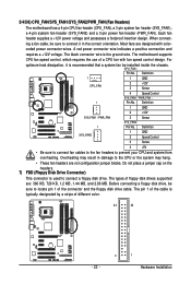
3/4/5/6) CPU_FAN/SYS_FAN1/SYS_FAN2/PWR_FAN (Fan Headers) The motherboard has a 4-pin CPU fan header (CPU_FAN), a 3-pin system fan header (SYS_FAN1), a 4-pin system fan header (SYS_FAN2) and a 3-pin power fan header (PWR_FAN). Do not place a ... connector wire is used to connect a floppy disk drive. CPU_FAN : Pin No. Each fan header supplies a +12V power voltage and possesses a foolproof insertion design. The motherboard supports CPU fan speed control, which requires the use of floppy disk drives supported are: 360 KB, 720 KB, 1.2 MB, 1.44 MB, and 2.88 MB...
3/4/5/6) CPU_FAN/SYS_FAN1/SYS_FAN2/PWR_FAN (Fan Headers) The motherboard has a 4-pin CPU fan header (CPU_FAN), a 3-pin system fan header (SYS_FAN1), a 4-pin system fan header (SYS_FAN2) and a 3-pin power fan header (PWR_FAN). Do not place a ... connector wire is used to connect a floppy disk drive. CPU_FAN : Pin No. Each fan header supplies a +12V power voltage and possesses a foolproof insertion design. The motherboard supports CPU fan speed control, which requires the use of floppy disk drives supported are: 360 KB, 720 KB, 1.2 MB, 1.44 MB, and 2.88 MB...


