Manual
Page 1
GA-EP35-DS3L/ GA-EP35-S3L LGA775 socket motherboard for Intel® CoreTM processor family/ Intel® Pentium® processor family/Intel® Celeron® processor family User's Manual Rev. 1002 12ME-EP35DS3L-1002R
GA-EP35-DS3L/ GA-EP35-S3L LGA775 socket motherboard for Intel® CoreTM processor family/ Intel® Pentium® processor family/Intel® Celeron® processor family User's Manual Rev. 1002 12ME-EP35DS3L-1002R

Manual
Page 2
Motherboard GA-EP35-DS3L/GA-EP35-S3L Feb. 1, 2008 Motherboard GA-EP35-DS3L/ GA-EP35-S3L Feb. 1, 2008
Motherboard GA-EP35-DS3L/GA-EP35-S3L Feb. 1, 2008 Motherboard GA-EP35-DS3L/ GA-EP35-S3L Feb. 1, 2008

Manual
Page 4
Table of Contents Box Contents ...6 OptionalItems...6 GA-EP35-DS3L/S3L Motherboard Layout 7 Block Diagram...8 Chapter 1 Hardware Installation 9 1-1 Installation Precautions 9 1-2 Product Specifications 10 1-3 Installing the CPU and CPU Cooler 13 1-3-1 Installing the CPU 13 1-3-2 Installing the ...
Table of Contents Box Contents ...6 OptionalItems...6 GA-EP35-DS3L/S3L Motherboard Layout 7 Block Diagram...8 Chapter 1 Hardware Installation 9 1-1 Installation Precautions 9 1-2 Product Specifications 10 1-3 Installing the CPU and CPU Cooler 13 1-3-1 Installing the CPU 13 1-3-2 Installing the ...

Manual
Page 6
... (Part No. 12CR1-1UB030-51R) 2-port SATA power cable (Part No. 12CF1-2SERPW-01R) S/PDIF in cable (Part No. 12CR1-1SPDIN-01R) - 6 - Box Contents GA-EP35-DS3L or GA-EP35-S3L motherboard Motherboard driver disk User's Manual Quick Installation Guide Intel® LGA775 CPU Installation Guide One IDE cable and one floppy disk drive cable Two...
... (Part No. 12CR1-1UB030-51R) 2-port SATA power cable (Part No. 12CF1-2SERPW-01R) S/PDIF in cable (Part No. 12CR1-1SPDIN-01R) - 6 - Box Contents GA-EP35-DS3L or GA-EP35-S3L motherboard Motherboard driver disk User's Manual Quick Installation Guide Intel® LGA775 CPU Installation Guide One IDE cable and one floppy disk drive cable Two...
Manual
Page 7
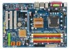
GA-EP35-DS3L/S3L Motherboard Layout KB_MS ATX_12V CPU_FAN COAXIAL OPTICAL LGA775 ATX PHASELED COM LPT DDRII1 GA-EP35-DS3L/S3L R_USB SYS_FAN2 USB LAN F_AUDIO AUDIO SYS_FAN1 PCIE_3 RTL8111B PCIE_16 PCIE_1 SPDIF_O CODEC PCIE_2 SPDIF_I PCI1 PCI2 IT8718 PCI3 CD_IN Intel® P35 FDD DDRII3 DDRII4 DDRII2 PWR_FAN Intel® ICH9 BAT CLR_CMOS SATAII0 SATAII1 JMicron 368 SATAII4 BIOS SATAII5 IDE1 F_USB3 F_USB2 F_USB1 CI F_PANEL PWR_LED "*" Only the GA-EP35-DS3L adopts All-Solid Capacitor design. - 7 -
GA-EP35-DS3L/S3L Motherboard Layout KB_MS ATX_12V CPU_FAN COAXIAL OPTICAL LGA775 ATX PHASELED COM LPT DDRII1 GA-EP35-DS3L/S3L R_USB SYS_FAN2 USB LAN F_AUDIO AUDIO SYS_FAN1 PCIE_3 RTL8111B PCIE_16 PCIE_1 SPDIF_O CODEC PCIE_2 SPDIF_I PCI1 PCI2 IT8718 PCI3 CD_IN Intel® P35 FDD DDRII3 DDRII4 DDRII2 PWR_FAN Intel® ICH9 BAT CLR_CMOS SATAII0 SATAII1 JMicron 368 SATAII4 BIOS SATAII5 IDE1 F_USB3 F_USB2 F_USB1 CI F_PANEL PWR_LED "*" Only the GA-EP35-DS3L adopts All-Solid Capacitor design. - 7 -

Manual
Page 10
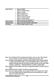
.../Intel® Pentium® 4 processor/ Intel® Celeron® processor in the LGA 775 package (Go to GIGABYTE's website for the latest CPU support list.) Š L2 cache varies with CPU Š 1333/1066/800 MHz... 1) Š Dual channel memory architecture Š Support for DDR2 1066/800/667 MHz memory modules (Go to GIGABYTE's website for the latest memory support list.) Š Realtek ALC888 codec Š High Definition Audio Š ... brackets connected to the internal USB headers) "*" Only the GA-EP35-DS3L adopts All-Solid Capacitor design. GA-EP35-DS3L/S3L Motherboard - 10 -
.../Intel® Pentium® 4 processor/ Intel® Celeron® processor in the LGA 775 package (Go to GIGABYTE's website for the latest CPU support list.) Š L2 cache varies with CPU Š 1333/1066/800 MHz... 1) Š Dual channel memory architecture Š Support for DDR2 1066/800/667 MHz memory modules (Go to GIGABYTE's website for the latest memory support list.) Š Realtek ALC888 codec Š High Definition Audio Š ... brackets connected to the internal USB headers) "*" Only the GA-EP35-DS3L adopts All-Solid Capacitor design. GA-EP35-DS3L/S3L Motherboard - 10 -
Manual
Page 12
... Intel® CoreTM 2 Extreme/ CoreTM 2 Quad/ CoreTM 2 Duo/ Pentium Dual-Core/ Celeron Dual-Core/ Celeron 400 Series CPU to enable support for Dynamic Energy Saver. GA-EP35-DS3L/S3L Motherboard - 12 -
... Intel® CoreTM 2 Extreme/ CoreTM 2 Quad/ CoreTM 2 Duo/ Pentium Dual-Core/ Celeron Dual-Core/ Celeron 400 Series CPU to enable support for Dynamic Energy Saver. GA-EP35-DS3L/S3L Motherboard - 12 -

Manual
Page 14
Step 5: Once the CPU is properly inserted, replace the load plate and push the CPU socket lever back into position. GA-EP35-DS3L/S3L Motherboard - 14 - CPU Socket Lever Step 1: Completely raise the CPU socket lever. Align the CPU pin one marking (triangle) with the pin one corner of ...
Step 5: Once the CPU is properly inserted, replace the load plate and push the CPU socket lever back into position. GA-EP35-DS3L/S3L Motherboard - 14 - CPU Socket Lever Step 1: Completely raise the CPU socket lever. Align the CPU pin one marking (triangle) with the pin one corner of ...
Manual
Page 16
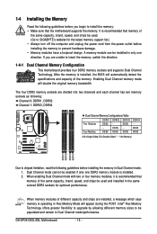
... design. DS/SS - - Intel® Flex Memory Technology offers greater flexibility to upgrade by allowing different memory sizes to be used . (Go to GIGABYTE's website for optimum performance. GA-EP35-DS3L/S3L Motherboard - 16 - It is installed, the BIOS will double the original memory bandwidth. After the memory is recommended that memory of different capacity...
... design. DS/SS - - Intel® Flex Memory Technology offers greater flexibility to upgrade by allowing different memory sizes to be used . (Go to GIGABYTE's website for optimum performance. GA-EP35-DS3L/S3L Motherboard - 16 - It is installed, the BIOS will double the original memory bandwidth. After the memory is recommended that memory of different capacity...

Manual
Page 18
... power cord from the power outlet before you begin to correctly install your expansion card(s). 7. If necessary, go to BIOS Setup to prevent hardware damage. GA-EP35-DS3L/S3L Motherboard - 18 - Make sure the metal contacts on the slot and then lift the card straight out from the chassis back panel. 2. Example: Installing and...
... power cord from the power outlet before you begin to correctly install your expansion card(s). 7. If necessary, go to BIOS Setup to prevent hardware damage. GA-EP35-DS3L/S3L Motherboard - 18 - Make sure the metal contacts on the slot and then lift the card straight out from the chassis back panel. 2. Example: Installing and...
Manual
Page 20
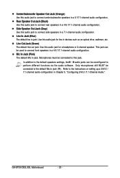
... default line out jack. In addition to the default speakers settings, the ~ audio jacks can be reconfigured to connect side speakers in a 4/5.1/7.1-channel audio configuration. GA-EP35-DS3L/S3L Motherboard - 20 - Line In Jack (Blue) The default line in jack. Only microphones still MUST be connected to this audio jack to perform different functions...
... default line out jack. In addition to the default speakers settings, the ~ audio jacks can be reconfigured to connect side speakers in a 4/5.1/7.1-channel audio configuration. GA-EP35-DS3L/S3L Motherboard - 20 - Line In Jack (Blue) The default line in jack. Only microphones still MUST be connected to this audio jack to perform different functions...

Manual
Page 22
... Definition 3.3V -12V GND PS_ON(soft On/Off) GND GND GND -5V +5V +5V +5V (Only for 2x12-pinATX) GND (Only for 2x12-pin ATX) GA-EP35-DS3L/S3L Motherboard - 22 -
... Definition 3.3V -12V GND PS_ON(soft On/Off) GND GND GND -5V +5V +5V +5V (Only for 2x12-pinATX) GND (Only for 2x12-pin ATX) GA-EP35-DS3L/S3L Motherboard - 22 -

Manual
Page 24
SATAII0 7 1 1 7 SATAII1 SATAII4 7 1 Pin No. 1 2 3 4 5 6 7 Definition GND TXP TXN GND RXN RXP GND GA-EP35-DS3L/S3L Motherboard 1 7 SATAII5 - 24 - Please connect the L-shaped end of the IDE devices (for example, master or slave). (For information about configuring master/slave settings for ...
SATAII0 7 1 1 7 SATAII1 SATAII4 7 1 Pin No. 1 2 3 4 5 6 7 Definition GND TXP TXN GND RXN RXP GND GA-EP35-DS3L/S3L Motherboard 1 7 SATAII5 - 24 - Please connect the L-shaped end of the IDE devices (for example, master or slave). (For information about configuring master/slave settings for ...

Manual
Page 26
... assignments of the module connector match the pin assignments of a single plug. For HD Front Panel Audio: For AC'97 Front Panel Audio: 1 2 Pin No. GA-EP35-DS3L/S3L Motherboard - 26 - The LED is off when the system is in S1 sleep state. You may connect your chassis provides an AC'97 front panel...
... assignments of the module connector match the pin assignments of a single plug. For HD Front Panel Audio: For AC'97 Front Panel Audio: 1 2 Pin No. GA-EP35-DS3L/S3L Motherboard - 26 - The LED is off when the system is in S1 sleep state. You may connect your chassis provides an AC'97 front panel...

Manual
Page 28
... cord from the power outlet to prevent damage to the USB bracket. Each USB header can provide two USB ports via an optional USB bracket. GA-EP35-DS3L/S3L Motherboard - 28 - For example, some graphics cards may require you wish to connect an HDMI display to USB 2.0/1.1 specification.
... cord from the power outlet to prevent damage to the USB bracket. Each USB header can provide two USB ports via an optional USB bracket. GA-EP35-DS3L/S3L Motherboard - 28 - For example, some graphics cards may require you wish to connect an HDMI display to USB 2.0/1.1 specification.
Manual
Page 30
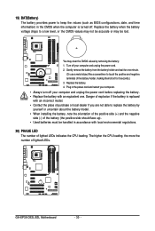
... environmental regulations. 20) PHASE LED The number of the battery holder, making them short for one . Danger of explosion if the battery is turned off. GA-EP35-DS3L/S3L Motherboard - 30 - Gently remove the battery from the battery holder and wait for 5 seconds.) 3. Plug in the CMOS when the computer is replaced with an...
... environmental regulations. 20) PHASE LED The number of the battery holder, making them short for one . Danger of explosion if the battery is turned off. GA-EP35-DS3L/S3L Motherboard - 30 - Gently remove the battery from the battery holder and wait for 5 seconds.) 3. Plug in the CMOS when the computer is replaced with an...
Manual
Page 32
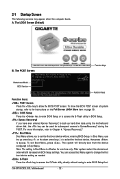
A. EP35-DS3L E12a . . . . : BIOS Setup/Q-Flash : XpressRecovery2 : Boot Menu : Qflash 12/25/2007-P35-ICH9-6A89OG0RC-00 Function Keys Function Keys: : POST Screen Press the key to ... 38. : BIOS Setup Press the key to enter BIOS Setup or to the instructions on the Full Screen LOGO Show item on BIOS Setup settings. GA-EP35-DS3L/S3L Motherboard - 32 - 2-1 Startup Screen The following screens may appear when the computer boots. To exit Boot Menu, press . The POST Screen Motherboard Model BIOS Version...
A. EP35-DS3L E12a . . . . : BIOS Setup/Q-Flash : XpressRecovery2 : Boot Menu : Qflash 12/25/2007-P35-ICH9-6A89OG0RC-00 Function Keys Function Keys: : POST Screen Press the key to ... 38. : BIOS Setup Press the key to enter BIOS Setup or to the instructions on the Full Screen LOGO Show item on BIOS Setup settings. GA-EP35-DS3L/S3L Motherboard - 32 - 2-1 Startup Screen The following screens may appear when the computer boots. To exit Boot Menu, press . The POST Screen Motherboard Model BIOS Version...

Manual
Page 34
You can also carry out this task.) GA-EP35-DS3L/S3L Motherboard - 34 - First select the profile you can also carry out this task.) „ Exit Without Saving Abandon all the power-saving functions. „ PnP/...
You can also carry out this task.) GA-EP35-DS3L/S3L Motherboard - 34 - First select the profile you can also carry out this task.) „ Exit Without Saving Abandon all the power-saving functions. „ PnP/...
Manual
Page 36
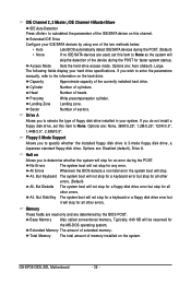
... currently installed hard drive. If you wish to enter the parameters manually, refer to the information on the system. Capacity Approximate capacity of extended memory. GA-EP35-DS3L/S3L Motherboard - 36 - Cylinder Number of sectors. Sector Number of cylinders. No Errors The system boot will stop for all other errors. Precomp Write precompensation cylinder...
... currently installed hard drive. If you wish to enter the parameters manually, refer to the information on the system. Capacity Approximate capacity of extended memory. GA-EP35-DS3L/S3L Motherboard - 36 - Cylinder Number of sectors. Sector Number of cylinders. No Errors The system boot will stop for all other errors. Precomp Write precompensation cylinder...

Manual
Page 38
... NT4.0. (Default: Disabled) No-Execute Memory Protect (Note) Enables or disables Intel® Execute Disable Bit function. GA-EP35-DS3L/S3L Motherboard - 38 - to 3 (Note) Allows you install a CPU that supports this item to display the GIGABYTE Logo at system startup. Depending on CPU loading, Intel® EIST technology can function as the first display...
... NT4.0. (Default: Disabled) No-Execute Memory Protect (Note) Enables or disables Intel® Execute Disable Bit function. GA-EP35-DS3L/S3L Motherboard - 38 - to 3 (Note) Allows you install a CPU that supports this item to display the GIGABYTE Logo at system startup. Depending on CPU loading, Intel® EIST technology can function as the first display...