Manual
Page 3
..."REV: X.X." For product-related information, check on our website at: http://www.gigabyte.com.tw Identifying Your Motherboard Revision The revision number on your motherboard revision before updating motherboard BIOS, drivers, or when looking for technical information. For example, "REV: 1.0" means ...the revision of the motherboard is the property of GIGABYTE. No part of documentations: For detailed product ...
..."REV: X.X." For product-related information, check on our website at: http://www.gigabyte.com.tw Identifying Your Motherboard Revision The revision number on your motherboard revision before updating motherboard BIOS, drivers, or when looking for technical information. For example, "REV: 1.0" means ...the revision of the motherboard is the property of GIGABYTE. No part of documentations: For detailed product ...
Manual
Page 4
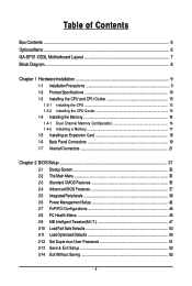
Table of Contents Box Contents ...6 OptionalItems...6 GA-EP31-DS3L Motherboard Layout 7 Block Diagram...8 Chapter 1 Hardware Installation 9 1-1 Installation Precautions 9 1-2 Product Specifications 10 1-3 Installing the CPU and CPU Cooler 13 ... Memory 17 1-5 Installing an Expansion Card 18 1-6 Back Panel Connectors 19 1-7 Internal Connectors 21 Chapter 2 BIOS Setup 31 2-1 Startup Screen 32 2-2 The Main Menu 33 2-3 Standard CMOS Features 35 2-4 Advanced BIOS Features 37 2-5 IntegratedPeripherals 39 2-6 Power Management Setup 42 2-7 PnP/PCI Configurations 44 2-8 PC Health Status ...
Table of Contents Box Contents ...6 OptionalItems...6 GA-EP31-DS3L Motherboard Layout 7 Block Diagram...8 Chapter 1 Hardware Installation 9 1-1 Installation Precautions 9 1-2 Product Specifications 10 1-3 Installing the CPU and CPU Cooler 13 ... Memory 17 1-5 Installing an Expansion Card 18 1-6 Back Panel Connectors 19 1-7 Internal Connectors 21 Chapter 2 BIOS Setup 31 2-1 Startup Screen 32 2-2 The Main Menu 33 2-3 Standard CMOS Features 35 2-4 Advanced BIOS Features 37 2-5 IntegratedPeripherals 39 2-6 Power Management Setup 42 2-7 PnP/PCI Configurations 44 2-8 PC Health Status ...

Manual
Page 5
... 54 3-3 Technical Manuals 54 3-4 Contact ...55 3-5 System ...55 3-6 Download Center 56 Chapter 4 Unique Features 57 4-1 Xpress Recovery2 57 4-2 BIOS Update Utilities 62 4-2-1 Updating the BIOS with the Q-Flash Utility 62 4-2-2 Updating the BIOS with the @BIOS Utility 65 4-3 EasyTune 6 ...66 4-4 Dynamic Energy Saver Advanced 67 Chapter 5 Appendix ...69 5-1 Configuring Audio Input and Output 69...
... 54 3-3 Technical Manuals 54 3-4 Contact ...55 3-5 System ...55 3-6 Download Center 56 Chapter 4 Unique Features 57 4-1 Xpress Recovery2 57 4-2 BIOS Update Utilities 62 4-2-1 Updating the BIOS with the Q-Flash Utility 62 4-2-2 Updating the BIOS with the @BIOS Utility 65 4-3 EasyTune 6 ...66 4-4 Dynamic Energy Saver Advanced 67 Chapter 5 Appendix ...69 5-1 Configuring Audio Input and Output 69...

Manual
Page 8
Block Diagram PCIe CLK (100 MHz) LGA775 Processor CPU CLK+/(333/266/200 MHz) 1 PCI Express x16 Host Interface DDR2 1066/800/667 MHz PCI Express Bus PCI Express x16 LAN RJ45 RTL 8111C x1 3 PCI Express x1 x 1 x 1 x 1 PCIe CLK (100 MHz) PCI Bus Intel® P31/G31 Intel® ICH7 CODEC Dual Channel Memory MCH CLK (333/266/200 MHz) Dual BIOS ATA-100/66/33 IDE Channel 4 SATA 3Gb/s 8 USB Ports IT8718 Floppy LPT Port COM Port PS/2 KB/Mouse Surround Speaker Out Center/Subwoofer Speaker Out Side Speaker Out MIC Line-Out Line-In SPDIF In SPDIF Out 3 PCI PCI CLK (33 MHz) - 8 -
Block Diagram PCIe CLK (100 MHz) LGA775 Processor CPU CLK+/(333/266/200 MHz) 1 PCI Express x16 Host Interface DDR2 1066/800/667 MHz PCI Express Bus PCI Express x16 LAN RJ45 RTL 8111C x1 3 PCI Express x1 x 1 x 1 x 1 PCIe CLK (100 MHz) PCI Bus Intel® P31/G31 Intel® ICH7 CODEC Dual Channel Memory MCH CLK (333/266/200 MHz) Dual BIOS ATA-100/66/33 IDE Channel 4 SATA 3Gb/s 8 USB Ports IT8718 Floppy LPT Port COM Port PS/2 KB/Mouse Surround Speaker Out Center/Subwoofer Speaker Out Side Speaker Out MIC Line-Out Line-In SPDIF In SPDIF Out 3 PCI PCI CLK (33 MHz) - 8 -

Manual
Page 11
... Š CPU/System/Power fan speed detection Š CPU overheating warning Š CPU/System/Power fan fail warning Š CPU/System fan speed control(Note 2) BIOS Š 2 x 8 Mbit flash Š Use of licensed AWARD BIOS Š Support for DualBIOSTM Š PnP 1.0a, DMI 2.0, SM...
... Š CPU/System/Power fan speed detection Š CPU overheating warning Š CPU/System/Power fan fail warning Š CPU/System fan speed control(Note 2) BIOS Š 2 x 8 Mbit flash Š Use of licensed AWARD BIOS Š Support for DualBIOSTM Š PnP 1.0a, DMI 2.0, SM...

Manual
Page 12
For example, 4 GB of memory is less than the stated amount. GA-EP31-DS3L Motherboard - 12 - Unique Features Bundled Software Operating System Form Factor Š Support for @BIOS Š Support for Download Center Š Support for Q-Flash Š Support for EasyTune (Note 3) Š Support... for Xpress Install Š Support for Xpress Recovery2 Š Support for Virtual Dual BIOS Š Support for Dynamic Energy Saver Advanced (Note 4) Š Norton Internet Security (OEM version) Š Support for Microsoft® Windows&#...
For example, 4 GB of memory is less than the stated amount. GA-EP31-DS3L Motherboard - 12 - Unique Features Bundled Software Operating System Form Factor Š Support for @BIOS Š Support for Download Center Š Support for Q-Flash Š Support for EasyTune (Note 3) Š Support... for Xpress Install Š Support for Xpress Recovery2 Š Support for Virtual Dual BIOS Š Support for Dynamic Energy Saver Advanced (Note 4) Š Norton Internet Security (OEM version) Š Support for Microsoft® Windows&#...
Manual
Page 16
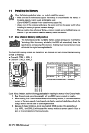
.../SS - - When enabling Dual Channel mode with double-sided memory modules to prevent system's failure to GIGABYTE's website for optimum performance. 3. A memory module can be enabled if only one direction. If you begin..., and chips be used . (Go to start or incorrect detection of the same channel (e.g. GA-EP31-DS3L Motherboard - 16 - DS/SS - - Dual Channel mode cannot be installed in the first table...the memory. DDR2_1 and DDR2_2) with two or four memory modules, it is installed, the BIOS will double the original memory bandwidth. DS/SS DS/SS - - - - Enabling Dual ...
.../SS - - When enabling Dual Channel mode with double-sided memory modules to prevent system's failure to GIGABYTE's website for optimum performance. 3. A memory module can be enabled if only one direction. If you begin..., and chips be used . (Go to start or incorrect detection of the same channel (e.g. GA-EP31-DS3L Motherboard - 16 - DS/SS - - Dual Channel mode cannot be installed in the first table...the memory. DDR2_1 and DDR2_2) with two or four memory modules, it is installed, the BIOS will double the original memory bandwidth. DS/SS DS/SS - - - - Enabling Dual ...
Manual
Page 18
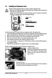
...expansion card. • Always turn off the computer and unplug the power cord from the power outlet before you begin to make any required BIOS changes for your expansion card(s). 7. Example: Installing and Removing a PCI Express x16 Graphics Card: • Installing a Graphics Card: Gently ...all expansion cards, replace the chassis cover(s). 6. Make sure the graphics card is fully seated in your expansion card in the expansion slot. 1. GA-EP31-DS3L Motherboard - 18 - Align the card with the expansion card in the slot. 3. Locate an expansion slot that came with a screw. 5. Turn...
...expansion card. • Always turn off the computer and unplug the power cord from the power outlet before you begin to make any required BIOS changes for your expansion card(s). 7. Example: Installing and Removing a PCI Express x16 Graphics Card: • Installing a Graphics Card: Gently ...all expansion cards, replace the chassis cover(s). 6. Make sure the graphics card is fully seated in your expansion card in the expansion slot. 1. GA-EP31-DS3L Motherboard - 18 - Align the card with the expansion card in the slot. 3. Locate an expansion slot that came with a screw. 5. Turn...

Manual
Page 26
...way to turn off (S5). • PW (Power Switch, Red): Connects to the power switch on the chassis front panel. If a problem is detected, the BIOS may differ by issuing a beep code. Refer to Chapter 5, "Troubleshooting," for more information). • SPEAK (Speaker, Orange): Connects to perform a normal restart. ...S0 On LED is on the chassis front panel to this header, make sure the wire assignments and the pin assignments are matched correctly. GA-EP31-DS3L Motherboard - 26 - The LED keeps blinking when S1 Blinking the system is in S1 sleep state. The LED is off when the ...
...way to turn off (S5). • PW (Power Switch, Red): Connects to the power switch on the chassis front panel. If a problem is detected, the BIOS may differ by issuing a beep code. Refer to Chapter 5, "Troubleshooting," for more information). • SPEAK (Speaker, Orange): Connects to perform a normal restart. ...S0 On LED is on the chassis front panel to this header, make sure the wire assignments and the pin assignments are matched correctly. GA-EP31-DS3L Motherboard - 26 - The LED keeps blinking when S1 Blinking the system is in S1 sleep state. The LED is off when the ...
Manual
Page 29
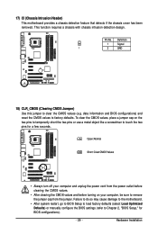
... intrusion detection design. date information and BIOS configurations) and reset the CMOS values to clear the CMOS values (e.g. Hardware Installation Failure to do so may cause damage to the motherboard. • After system restart, go to BIOS Setup to load factory defaults (select Load... Optimized Defaults) or manually configure the BIOS settings (refer to touch the two pins for BIOS configurations). - 29 - 17) CI (Chassis Intrusion Header) This motherboard ...
... intrusion detection design. date information and BIOS configurations) and reset the CMOS values to clear the CMOS values (e.g. Hardware Installation Failure to do so may cause damage to the motherboard. • After system restart, go to BIOS Setup to load factory defaults (select Load... Optimized Defaults) or manually configure the BIOS settings (refer to touch the two pins for BIOS configurations). - 29 - 17) CI (Chassis Intrusion Header) This motherboard ...

Manual
Page 30
... the power cord and restart your computer. • Always turn off . Gently remove the battery from the battery holder and wait for 5 seconds.) 3. GA-EP31-DS3L Motherboard - 30 - The higher the CPU loading, the more the number of the battery (the positive side should face up). • Used batteries must... be lost. 19) BAT(Battery) The battery provides power to keep the values (such as BIOS configurations, date, and time information) in the CMOS when the computer is replaced with an incorrect model. • Contact the place of purchase ...
... the power cord and restart your computer. • Always turn off . Gently remove the battery from the battery holder and wait for 5 seconds.) 3. GA-EP31-DS3L Motherboard - 30 - The higher the CPU loading, the more the number of the battery (the positive side should face up). • Used batteries must... be lost. 19) BAT(Battery) The battery provides power to keep the values (such as BIOS configurations, date, and time information) in the CMOS when the computer is replaced with an incorrect model. • Contact the place of purchase ...

Manual
Page 31
...default values. (Refer to Chapter 4, "BIOS Update Utilities." • Because BIOS flashing is turned on the motherboard. Inadequately altering the settings may result in the main menu of BIOS, it with caution. To upgrade the BIOS, use either the GIGABYTE Q-Flash or @BIOS utility. • Q-Flash allows the... user to quickly and easily upgrade or back up BIOS without entering the operating system. • @BIOS is recommended that you do ...
...default values. (Refer to Chapter 4, "BIOS Update Utilities." • Because BIOS flashing is turned on the motherboard. Inadequately altering the settings may result in the main menu of BIOS, it with caution. To upgrade the BIOS, use either the GIGABYTE Q-Flash or @BIOS utility. • Q-Flash allows the... user to quickly and easily upgrade or back up BIOS without entering the operating system. • @BIOS is recommended that you do ...
Manual
Page 32
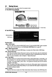
...< > to select the first boot device, then press to XpressRecovery2 during the POST. GA-EP31-DS3L Motherboard - 32 - To show the BIOS POST screen. The LOGO Screen (Default) :POST Screen :BIOS Setup/Q-Flash :XpressRecovery2 :Boot Menu :Qflash Function Keys B. Motherboard Model BIOS Version EP31-DS3L E5 . . . . : BIOS Setup : XpressRecovery2 : Boot Menu : Qflash 07/21/2008-P31-ICH7-6A99OG09C-00...
...< > to select the first boot device, then press to XpressRecovery2 during the POST. GA-EP31-DS3L Motherboard - 32 - To show the BIOS POST screen. The LOGO Screen (Default) :POST Screen :BIOS Setup/Q-Flash :XpressRecovery2 :Boot Menu :Qflash Function Keys B. Motherboard Model BIOS Version EP31-DS3L E5 . . . . : BIOS Setup : XpressRecovery2 : Boot Menu : Qflash 07/21/2008-P31-ICH7-6A99OG09C-00...

Manual
Page 33
... description of a highlighted setup option is displayed on the bottom line of the submenu. • If you do not find the settings you enter the BIOS Setup program, the Main Menu (as usual, select the Load Optimized Defaults item to set your system to exit the help screen (General Help) of... Saving ESC: Quit F8: Q-Flash KLJI: Select Item F10: Save & Exit Setup F11: Save CMOS to display a help screen. Press to its defaults. • The BIOS Setup menus described in the Main Menu or a submenu, press + to access more advanced options. • When the system is in the Item Help block...
... description of a highlighted setup option is displayed on the bottom line of the submenu. • If you do not find the settings you enter the BIOS Setup program, the Main Menu (as usual, select the Load Optimized Defaults item to set your system to exit the help screen (General Help) of... Saving ESC: Quit F8: Q-Flash KLJI: Select Item F10: Save & Exit Setup F11: Save CMOS to display a help screen. Press to its defaults. • The BIOS Setup menus described in the Main Menu or a submenu, press + to access more advanced options. • When the system is in the Item Help block...
Manual
Page 34
Pressing to the confirmation message will exit BIOS Setup. (Pressing can use the SPACE key) and then press to see information about autodetected system/CPU temperature, system voltage and fan speed, etc. „ MB Intelligent Tweaker(M.I.T.) Use this task.) GA-EP31-DS3L Motherboard - 34 - First select the profile you wish to load, then press to...
Pressing to the confirmation message will exit BIOS Setup. (Pressing can use the SPACE key) and then press to see information about autodetected system/CPU temperature, system voltage and fan speed, etc. „ MB Intelligent Tweaker(M.I.T.) Use this task.) GA-EP31-DS3L Motherboard - 34 - First select the profile you wish to load, then press to...
Manual
Page 35
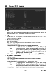
...Extended IDE Drive Configure your IDE/SATA devices by using one of the two methods below : • Auto • None • Manual Lets BIOS automatically detect IDE/SATA devices during the POST. (Default) If no IDE/SATA devices are used , set this item to autodetect the parameters of ...the three methods below : • Auto Lets BIOS automatically detect IDE/SATA devices during the POST. (Default) • None If no IDE/SATA devices are used , set the time. IDE Channel 0...
...Extended IDE Drive Configure your IDE/SATA devices by using one of the two methods below : • Auto • None • Manual Lets BIOS automatically detect IDE/SATA devices during the POST. (Default) If no IDE/SATA devices are used , set this item to autodetect the parameters of ...the three methods below : • Auto Lets BIOS automatically detect IDE/SATA devices during the POST. (Default) • None If no IDE/SATA devices are used , set the time. IDE Channel 0...

Manual
Page 36
The following fields display your system. Cylinder Number of the currently installed hard drive. Landing Zone Landing zone. GA-EP31-DS3L Motherboard - 36 - If you wish to enter the parameters manually, refer to the information on Allows you to specify whether the... disk drive, set this item to determine whether the system will stop for all other errors. Options are determined by the BIOS POST. All Errors Whenever the BIOS detects a non-fatal error the system boot will not stop . Capacity Approximate capacity of cylinders. No Errors The system boot...
The following fields display your system. Cylinder Number of the currently installed hard drive. Landing Zone Landing zone. GA-EP31-DS3L Motherboard - 36 - If you wish to enter the parameters manually, refer to the information on Allows you to specify whether the... disk drive, set this item to determine whether the system will stop for all other errors. Options are determined by the BIOS POST. All Errors Whenever the BIOS detects a non-fatal error the system boot will not stop . Capacity Approximate capacity of cylinders. No Errors The system boot...
Manual
Page 37
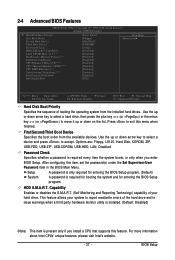
... of the hard drive and to exit this item, set the password(s) under the Set Supervisor/User Password item in the BIOS Main Menu. HDD S.M.A.R.T. BIOS Setup Press to issue warnings when a third party hardware monitor utility is installed. (Default: Disabled) (Note) This item... is present only if you enter BIOS Setup. After configuring this menu when finished. Capability Enables or disables the S.M.A.R.T. (Self Monitoring and Reporting Technology) capability of loading the...
... of the hard drive and to exit this item, set the password(s) under the Set Supervisor/User Password item in the BIOS Main Menu. HDD S.M.A.R.T. BIOS Setup Press to issue warnings when a third party hardware monitor utility is installed. (Default: Disabled) (Note) This item... is present only if you enter BIOS Setup. After configuring this menu when finished. Capability Enables or disables the S.M.A.R.T. (Self Monitoring and Reporting Technology) capability of loading the...
Manual
Page 39
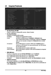
...as needed. (Default) Combined Sets all SATA devices to operate in PATA mode. Enhanced Sets all SATA devices to Combined or Enhanced mode. BIOS Setup If your onboard SATA controller is dependent on the On-Chip SATA Mode and PATA IDE Set to Ch. 1 Master/Slave. Disabled ... Non-Combined is configured to Ch. 1 Master/Slave, this option will be used simultaneously: two PATA devices plus two SATA devices. Auto Lets BIOS set to USB Controller USB 2.0 Controller USB Keyboard Support USB Mouse Support Legacy USB storage detect Azalia Codec Onboard H/W LAN ` SMART LAN Onboard ...
...as needed. (Default) Combined Sets all SATA devices to operate in PATA mode. Enhanced Sets all SATA devices to Combined or Enhanced mode. BIOS Setup If your onboard SATA controller is dependent on the On-Chip SATA Mode and PATA IDE Set to Ch. 1 Master/Slave. Disabled ... Non-Combined is configured to Ch. 1 Master/Slave, this option will be used simultaneously: two PATA devices plus two SATA devices. Auto Lets BIOS set to USB Controller USB 2.0 Controller USB Keyboard Support USB Mouse Support Legacy USB storage detect Azalia Codec Onboard H/W LAN ` SMART LAN Onboard ...
Manual
Page 41
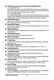
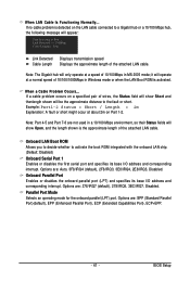
... at Port..... Options are : 378/IRQ7 (default), 278/IRQ5, 3BC/IRQ7, Disabled. Parallel Port Mode Selects an operating mode for the onboard parallel (LPT) port. BIOS Setup Link Detected --> 100Mbps Cable Length= 30m Link Detected Cable Length Displays transmission speed Displays the approximate length of wires, the Status field will show...
... at Port..... Options are : 378/IRQ7 (default), 278/IRQ5, 3BC/IRQ7, Disabled. Parallel Port Mode Selects an operating mode for the onboard parallel (LPT) port. BIOS Setup Link Detected --> 100Mbps Cable Length= 30m Link Detected Cable Length Displays transmission speed Displays the approximate length of wires, the Status field will show...


