
Manual
Page 7
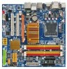
IT8718 GA-EG45M-DS2H Motherboard Layout KB_USB ATX_12V VGA DVI OPTICAL HDMI Level Shifter Level Shifter LGA775 PHASE LED TPM IC (Note) LPT FDD GA-EG45M-DS2H CPU_FAN USB 1394 ESATA LAN USB BAT Intel® G45 F_AUDIO AUDIO SYS_FAN PCIEX4 PCI1 RTL 8111C PCI2 SPDIF_O CD_IN CODEC SPDIF_I PCIEX1 M_BIOS B_BIOS TSB43AB23 COMA F1_1394 F_USB3 F_USB1 Intel® ICH10R SATA2_2SATA2_0 F_USB2 SATA2_3 SATA2_1 SATA2_4 IT8213 CLR_CMOS IDE DDR2_1 DDR2_2 DDR2_3 DDR2_4 F_PANEL ATX PWR_LED CI (Note) This feature is optional due to different regional policy. - 7 -
IT8718 GA-EG45M-DS2H Motherboard Layout KB_USB ATX_12V VGA DVI OPTICAL HDMI Level Shifter Level Shifter LGA775 PHASE LED TPM IC (Note) LPT FDD GA-EG45M-DS2H CPU_FAN USB 1394 ESATA LAN USB BAT Intel® G45 F_AUDIO AUDIO SYS_FAN PCIEX4 PCI1 RTL 8111C PCI2 SPDIF_O CD_IN CODEC SPDIF_I PCIEX1 M_BIOS B_BIOS TSB43AB23 COMA F1_1394 F_USB3 F_USB1 Intel® ICH10R SATA2_2SATA2_0 F_USB2 SATA2_3 SATA2_1 SATA2_4 IT8213 CLR_CMOS IDE DDR2_1 DDR2_2 DDR2_3 DDR2_4 F_PANEL ATX PWR_LED CI (Note) This feature is optional due to different regional policy. - 7 -
Manual
Page 11
... Š 1 x S/PDIF In header Š 1 x S/PDIF Out header Š 3 x USB 2.0/1.1 headers Š 1 x IEEE 1394a header Š 1 x parallel port header Š 1 x serial port header Š 1 x power LED header Š 1 x chassis intrusion header Back Panel Š 1 x PS/2 keyboard or PS/2 mouse port Connectors Š 1 x D-Sub port Š 1 x DVI-D port (Note 3) Š 1 x HDMI port...
... Š 1 x S/PDIF In header Š 1 x S/PDIF Out header Š 3 x USB 2.0/1.1 headers Š 1 x IEEE 1394a header Š 1 x parallel port header Š 1 x serial port header Š 1 x power LED header Š 1 x chassis intrusion header Back Panel Š 1 x PS/2 keyboard or PS/2 mouse port Connectors Š 1 x D-Sub port Š 1 x DVI-D port (Note 3) Š 1 x HDMI port...

Manual
Page 22
... Dual-Core processor • Memory: Two 1 GB DDR2 800 memory modules with SATA 1.5Gb/s standard. Connection/ Speed LED Activity LED LAN Port Connection/Speed LED: State Description Orange 1 Gbps data rate Green 100 Mbps data rate Off 10 Mbps data rate Activity... • HDCP compliant monitor(s) Optical S/PDIF Out Connector This connector provides digital audio out to SATA 3Gb/s standard and is occurring GA-EG45M-DS2H Motherboard - 22 - Dual Display Configurations: This motherboard provides three display ports, DVI-D, HDMI, and D-Sub ports and supports dualdisplay configurations...
... Dual-Core processor • Memory: Two 1 GB DDR2 800 memory modules with SATA 1.5Gb/s standard. Connection/ Speed LED Activity LED LAN Port Connection/Speed LED: State Description Orange 1 Gbps data rate Green 100 Mbps data rate Off 10 Mbps data rate Activity... • HDCP compliant monitor(s) Optical S/PDIF Out Connector This connector provides digital audio out to SATA 3Gb/s standard and is occurring GA-EG45M-DS2H Motherboard - 22 - Dual Display Configurations: This motherboard provides three display ports, DVI-D, HDMI, and D-Sub ports and supports dualdisplay configurations...
Manual
Page 24
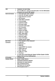
GA-EG45M-DS2H Motherboard - 24 - 1-7 Internal Connectors 1 21 18 5 19 3 11 4 2 9 7 13 8 12 10 14 17 16 15 6 20 1) ATX_12V 2) ATX 3) CPU_FAN 4) SYS_FAN 5) FDD 6) IDE 7) SATA2_0/1/2/3/4 8) PWR_LED 9) CI ...) F_PANEL 11) F_AUDIO 12) CD_IN 13) SPDIF_O 14) SPDIF_I 15) F_USB1/F_USB2/F_USB3 16) F1_1394 17) COMA 18) LPT 19) BAT 20) CLR_CMOS 21) PHASE LED Read the following guidelines before turning on the motherboard. Unplug the power cord from the power outlet to prevent damage to the devices. • After...
GA-EG45M-DS2H Motherboard - 24 - 1-7 Internal Connectors 1 21 18 5 19 3 11 4 2 9 7 13 8 12 10 14 17 16 15 6 20 1) ATX_12V 2) ATX 3) CPU_FAN 4) SYS_FAN 5) FDD 6) IDE 7) SATA2_0/1/2/3/4 8) PWR_LED 9) CI ...) F_PANEL 11) F_AUDIO 12) CD_IN 13) SPDIF_O 14) SPDIF_I 15) F_USB1/F_USB2/F_USB3 16) F1_1394 17) COMA 18) LPT 19) BAT 20) CLR_CMOS 21) PHASE LED Read the following guidelines before turning on the motherboard. Unplug the power cord from the power outlet to prevent damage to the devices. • After...

Manual
Page 28
...connect a system power LED on when the system is operating. Definition 1 Signal 2 GND 1 GA-EG45M-DS2H Motherboard - 28 - The LED is off (S5). 8) PWR_LED (System Power LED Header) This header can be used to indicate system power status. Pin No. 1 2 3 Definition MPD+ MPDMPD- 1 System Status LED S0 On S1 ...Chassis Intrusion Header) This motherboard provides a chassis detection feature that detects if the chassis cover has been removed. Pin No. The LED keeps blinking when the system is in S3/S4 sleep state or powered off when the system is in S1 sleep state. This...
...connect a system power LED on when the system is operating. Definition 1 Signal 2 GND 1 GA-EG45M-DS2H Motherboard - 28 - The LED is off (S5). 8) PWR_LED (System Power LED Header) This header can be used to indicate system power status. Pin No. 1 2 3 Definition MPD+ MPDMPD- 1 System Status LED S0 On S1 ...Chassis Intrusion Header) This motherboard provides a chassis detection feature that detects if the chassis cover has been removed. Pin No. The LED keeps blinking when the system is in S3/S4 sleep state or powered off when the system is in S1 sleep state. This...

Manual
Page 29
...panel. Refer to Chapter 5, "Troubleshooting," for more information). • SPEAK (Speaker, Orange): Connects to the speaker on the chassis front panel. The LED is on when the hard drive is detected, the BIOS may configure the way to turn off (S5). • PW (Power Switch, Red): ...the power switch (refer to Chapter 2, "BIOS Setup," "Power Management Setup," for information about beep codes. • HD (Hard Drive Activity LED, Blue) Connects to the power switch on when the system is detected at system startup. Note the positive and negative pins before connecting the cables...
...panel. Refer to Chapter 5, "Troubleshooting," for more information). • SPEAK (Speaker, Orange): Connects to the speaker on the chassis front panel. The LED is on when the hard drive is detected, the BIOS may configure the way to turn off (S5). • PW (Power Switch, Red): ...the power switch (refer to Chapter 2, "BIOS Setup," "Power Management Setup," for information about beep codes. • HD (Hard Drive Activity LED, Blue) Connects to the power switch on when the system is detected at system startup. Note the positive and negative pins before connecting the cables...

Manual
Page 35
Hardware Installation The higher the CPU loading, the more the number of lighted LEDs indicates the CPU loading. 21) PHASE LED The number of lighted LEDs. - 35 -
Hardware Installation The higher the CPU loading, the more the number of lighted LEDs indicates the CPU loading. 21) PHASE LED The number of lighted LEDs. - 35 -

Manual
Page 77
...GIGABYTE Dynamic Energy Saver Advanced shows how much power they have saved in taskbar) 16 INFO/Help 17 Live Utility Update (Check for the latest utility version) • The above data is for reference only. Button Information Table Button Description 1 Dynamic Energy Saver On/Off Switch (Default: Off) 2 Motherboard Phase LED...vary depending on testing method. - 77 - Unique Features Featuring an advanced proprietary hardware and software design, GIGABYTE Dynamic Energy Saver Advanced is a revolutionary technology that delivers unparalleled power savings with a click of time....
...GIGABYTE Dynamic Energy Saver Advanced shows how much power they have saved in taskbar) 16 INFO/Help 17 Live Utility Update (Check for the latest utility version) • The above data is for reference only. Button Information Table Button Description 1 Dynamic Energy Saver On/Off Switch (Default: Off) 2 Motherboard Phase LED...vary depending on testing method. - 77 - Unique Features Featuring an advanced proprietary hardware and software design, GIGABYTE Dynamic Energy Saver Advanced is a revolutionary technology that delivers unparalleled power savings with a click of time....

Manual
Page 78
...(Check for the first time (Note 4). Button Information Table Button Description 1 Dynamic Energy Saver On/Off Switch (Default: Off) 2 Motherboard Phase LED On/Off Switch (Default: On) 3 Dynamic CPU Frequency Function On/Off Switch (Default: Off) 4 CPU Throttling Display 5 3-Level CPU Voltage...8 Current CPU Power Consumption 9 Time/Date Dynamic Energy Saver Enabled 10 Total Power Savings (Total power saving with Dynamic Frequency Function; GA-EG45M-DS2H Motherboard - 78 - Total Mode In Total Mode, users are set to Enabled. (Note 2) Maximize system power saving with Dynamic ...
...(Check for the first time (Note 4). Button Information Table Button Description 1 Dynamic Energy Saver On/Off Switch (Default: Off) 2 Motherboard Phase LED On/Off Switch (Default: On) 3 Dynamic CPU Frequency Function On/Off Switch (Default: Off) 4 CPU Throttling Display 5 3-Level CPU Voltage...8 Current CPU Power Consumption 9 Time/Date Dynamic Energy Saver Enabled 10 Total Power Savings (Total power saving with Dynamic Frequency Function; GA-EG45M-DS2H Motherboard - 78 - Total Mode In Total Mode, users are set to Enabled. (Note 2) Maximize system power saving with Dynamic ...


