
Manual
Page 1
GA-EG41MFT-US2H LGA775 socket motherboard for Intel® Core™ processor family/ Intel® Pentium® processor family/Intel® Celeron® processor family User's Manual Rev. 1301 12ME-EG41FT2-1301R
GA-EG41MFT-US2H LGA775 socket motherboard for Intel® Core™ processor family/ Intel® Pentium® processor family/Intel® Celeron® processor family User's Manual Rev. 1301 12ME-EG41FT2-1301R

Manual
Page 2
Motherboard GA-EG41MFT-US2H Sept. 17, 2009 Motherboard GA-EG41MFT-US2H Sept. 17, 2009
Motherboard GA-EG41MFT-US2H Sept. 17, 2009 Motherboard GA-EG41MFT-US2H Sept. 17, 2009
Manual
Page 3
... Copyright © 2010 GIGA-BYTE TECHNOLOGY CO., LTD. Check your motherboard looks like this manual may be made by copyright laws and is the property of this manual are legally registered to use GIGABYTE's unique features, read the User's Manual. For instructions ...assist in this : "REV: X.X." All rights reserved. For product-related information, check on our website at: http://www.gigabyte.com Identifying Your Motherboard Revision The revision number on our website. The trademarks mentioned in this manual may be reproduced, copied, translated, transmitted, or...
... Copyright © 2010 GIGA-BYTE TECHNOLOGY CO., LTD. Check your motherboard looks like this manual may be made by copyright laws and is the property of this manual are legally registered to use GIGABYTE's unique features, read the User's Manual. For instructions ...assist in this : "REV: X.X." All rights reserved. For product-related information, check on our website at: http://www.gigabyte.com Identifying Your Motherboard Revision The revision number on our website. The trademarks mentioned in this manual may be reproduced, copied, translated, transmitted, or...

Manual
Page 4
Table of Contents Box Contents...6 Optional Items...6 GA-EG41MFT-US2H Motherboard Layout 7 GA-EG41MFT-US2H Motherboard Block Diagram 8 Chapter 1 Hardware Installation 9 1-1 Installation Precautions 9 1-2 Product Specifications 10 1-3 Installing the CPU and CPU Cooler 13 1-3-1 Installing the CPU 13 1-3-2 Installing the CPU Cooler ...
Table of Contents Box Contents...6 Optional Items...6 GA-EG41MFT-US2H Motherboard Layout 7 GA-EG41MFT-US2H Motherboard Block Diagram 8 Chapter 1 Hardware Installation 9 1-1 Installation Precautions 9 1-2 Product Specifications 10 1-3 Installing the CPU and CPU Cooler 13 1-3-1 Installing the CPU 13 1-3-2 Installing the CPU Cooler ...
Manual
Page 6
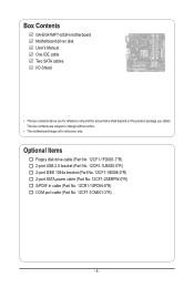
...-1IE008-0*R) 2-port SATA power cable (Part No. 12CF1-2SERPW-0*R) S/PDIF In cable (Part No. 12CR1-1SPDIN-0*R) COM port cable (Part No. 12CF1-1CM001-3*R) - 6 - Box Contents GA-EG41MFT-US2H motherboard Motherboard driver disk User's Manual One IDE cable Two SATA cables I/O Shield • The box contents above are subject to change without notice. • The...
...-1IE008-0*R) 2-port SATA power cable (Part No. 12CF1-2SERPW-0*R) S/PDIF In cable (Part No. 12CR1-1SPDIN-0*R) COM port cable (Part No. 12CF1-1CM001-3*R) - 6 - Box Contents GA-EG41MFT-US2H motherboard Motherboard driver disk User's Manual One IDE cable Two SATA cables I/O Shield • The box contents above are subject to change without notice. • The...

Manual
Page 7
TSB43AB23 SATA2_0 SATA2_2 CLR_CMOS F1_1394 F_USB1 F_USB2 F_PANEL - 7 - GA-EG41MFT-US2H Motherboard Layout KB_MS ATX_12V LGA775 PHASE LED iTE IT8718 VGA LAN DVI GA-EG41MFT-US2H HDMI Level Shifter Level Shifter Optical FDD USB_1394 USB BAT AUDIO F_AUDIO CPU_FAN PCIEX1 Realtek RTL8111D PCIEX16 PCI1 SPDIF_O PCI2 CODEC CD_IN COMA SPDIF_I Intel® G41 B_BIOS M_BIOS DDR3_1 DDR3_2 DDR3_3 DDR3_4 IDE ATX Intel® ICH7 SYS_FAN SATA2_1 SATA2_3 T.I.
TSB43AB23 SATA2_0 SATA2_2 CLR_CMOS F1_1394 F_USB1 F_USB2 F_PANEL - 7 - GA-EG41MFT-US2H Motherboard Layout KB_MS ATX_12V LGA775 PHASE LED iTE IT8718 VGA LAN DVI GA-EG41MFT-US2H HDMI Level Shifter Level Shifter Optical FDD USB_1394 USB BAT AUDIO F_AUDIO CPU_FAN PCIEX1 Realtek RTL8111D PCIEX16 PCI1 SPDIF_O PCI2 CODEC CD_IN COMA SPDIF_I Intel® G41 B_BIOS M_BIOS DDR3_1 DDR3_2 DDR3_3 DDR3_4 IDE ATX Intel® ICH7 SYS_FAN SATA2_1 SATA2_3 T.I.
Manual
Page 8
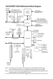
... Out 2 PCI PCI CLK (33 MHz) (Note 1) The PCI Express x16 slot share the PCI Express x16 bus with the HDMI and the DVI-D ports. GA-EG41MFT-US2H Motherboard Block Diagram PCIe CLK (100 MHz) 1 PCI Express x16 (Note 1) x8 LGA775 Processor CPU CLK+/(333/266/200 MHz) HDMI(Note 2) DVI-D(Note 2) Switch Switch...
... Out 2 PCI PCI CLK (33 MHz) (Note 1) The PCI Express x16 slot share the PCI Express x16 bus with the HDMI and the DVI-D ports. GA-EG41MFT-US2H Motherboard Block Diagram PCIe CLK (100 MHz) 1 PCI Express x16 (Note 1) x8 LGA775 Processor CPU CLK+/(333/266/200 MHz) HDMI(Note 2) DVI-D(Note 2) Switch Switch...

Manual
Page 9
...have an ESD wrist strap, keep your hands dry and first touch a metal object to eliminate static electricity. • Prior to installing the motherboard, please have a problem related to wear an electrostatic discharge (ESD) wrist strap when handling electronic com- Prior to installation, carefully read the.... - 9 - ponents such as physical harm to the user. • If you are connected tightly and securely. • When handling the motherboard, avoid touching any installation steps or have it on top of an antistatic pad or within the computer casing. • Do not place the computer...
...have an ESD wrist strap, keep your hands dry and first touch a metal object to eliminate static electricity. • Prior to installing the motherboard, please have a problem related to wear an electrostatic discharge (ESD) wrist strap when handling electronic com- Prior to installation, carefully read the.... - 9 - ponents such as physical harm to the user. • If you are connected tightly and securely. • When handling the motherboard, avoid touching any installation steps or have it on top of an antistatic pad or within the computer casing. • Do not place the computer...
Manual
Page 12
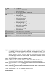
...-D ports become unavailable. (Note 4) You can use only one memory module is supported will drop down to 800 MHz. (Go to GIGABYTE's website for output when in EasyTune may differ by motherboard model. BIOS w w w w Unique Features w w w w w w w w w w w w Bundled Software w 2 x 8 Mbit flash Use of licensed AWARD BIOS Support for DualBIOS™ PnP 1.0a, DMI...
...-D ports become unavailable. (Note 4) You can use only one memory module is supported will drop down to 800 MHz. (Go to GIGABYTE's website for output when in EasyTune may differ by motherboard model. BIOS w w w w Unique Features w w w w w w w w w w w w Bundled Software w 2 x 8 Mbit flash Use of licensed AWARD BIOS Support for DualBIOS™ PnP 1.0a, DMI...
Manual
Page 13
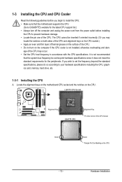
... the CPU. • Do not turn on the computer if the CPU cooler is not recommended that the motherboard supports the CPU. (Go to GIGABYTE's website for the peripherals. Locate the alignment keys on the motherboard CPU socket and the notches on the CPU - 13 - The CPU cannot be set the frequency beyond...
... the CPU. • Do not turn on the computer if the CPU cooler is not recommended that the motherboard supports the CPU. (Go to GIGABYTE's website for the peripherals. Locate the alignment keys on the motherboard CPU socket and the notches on the CPU - 13 - The CPU cannot be set the frequency beyond...
Manual
Page 14
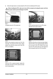
..., always replace the protective socket cover when the CPU is properly inserted, replace the load plate and push the CPU socket lever back into the motherboard CPU socket. B. Align the CPU pin one marking (triangle) with the pin one corner of the CPU socket (or you may align the CPU notches...
..., always replace the protective socket cover when the CPU is properly inserted, replace the load plate and push the CPU socket lever back into the motherboard CPU socket. B. Align the CPU pin one marking (triangle) with the pin one corner of the CPU socket (or you may align the CPU notches...
Manual
Page 15
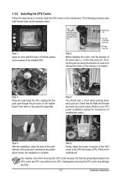
... of thermal grease on the surface of the CPU cooler to the CPU fan header (CPU_FAN) on the motherboard. Step 4: You should hear a "click" when pushing down on the motherboard. Hardware Installation Direction of the Arrow Sign on the Male Push Pin Male Push Pin The Top of Female...Before installing the cooler, note the direction of the arrow sign on the male push pin. (Turning the push pin along the direction of the motherboard. Check that the Male and Female push pins are joined closely. (Refer to your CPU cooler installation manual for instructions on installing the cooler.)...
... of thermal grease on the surface of the CPU cooler to the CPU fan header (CPU_FAN) on the motherboard. Step 4: You should hear a "click" when pushing down on the motherboard. Hardware Installation Direction of the Arrow Sign on the Male Push Pin Male Push Pin The Top of Female...Before installing the cooler, note the direction of the arrow sign on the male push pin. (Turning the push pin along the direction of the motherboard. Check that the Male and Female push pins are joined closely. (Refer to your CPU cooler installation manual for instructions on installing the cooler.)...

Manual
Page 16
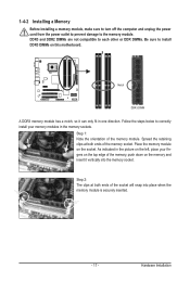
...four memory modules, it on the DDR3_1 and DDR3_3 sockets. Hardware Installation - 16 - It is to be used . (Go to GIGABYTE's website for the latest memory support list.) When memory modules of the memory. The four DDR3 memory sockets are divided into two ... Memory Read the following guidelines before you are unable to insert the memory, switch the direction. 1-4-1 Dual Channel Memory Configuration This motherboard provides four DDR3 memory sockets and supports Dual Channel Technology. Enabling Dual Channel memory mode will automatically detect the specifications and capacity of...
...four memory modules, it on the DDR3_1 and DDR3_3 sockets. Hardware Installation - 16 - It is to be used . (Go to GIGABYTE's website for the latest memory support list.) When memory modules of the memory. The four DDR3 memory sockets are divided into two ... Memory Read the following guidelines before you are unable to insert the memory, switch the direction. 1-4-1 Dual Channel Memory Configuration This motherboard provides four DDR3 memory sockets and supports Dual Channel Technology. Enabling Dual Channel memory mode will automatically detect the specifications and capacity of...
Manual
Page 17
... both ends of the memory module. Step 1: Note the orientation of the socket will snap into the memory socket. Place the memory module on this motherboard. Hardware Installation DDR3 and DDR2 DIMMs are not compatible to each other or DDR DIMMs. Be sure to the memory module. Spread the retaining clips...
... both ends of the memory module. Step 1: Note the orientation of the socket will snap into the memory socket. Place the memory module on this motherboard. Hardware Installation DDR3 and DDR2 DIMMs are not compatible to each other or DDR DIMMs. Be sure to the memory module. Spread the retaining clips...

Manual
Page 18
... BIOS Setup to make any required BIOS changes for your computer. Secure the card's metal bracket to install an expansion card: • Make sure the motherboard supports the expansion card. Example: Installing and Removing a PCI Express Graphics Card: • Installing a Graphics Card: Gently push down on the slot and then lift...
... BIOS Setup to make any required BIOS changes for your computer. Secure the card's metal bracket to install an expansion card: • Make sure the motherboard supports the expansion card. Example: Installing and Removing a PCI Express Graphics Card: • Installing a Graphics Card: Gently push down on the slot and then lift...

Manual
Page 20
... - 20 - Optical S/PDIF Out Connector This connector provides digital audio out to an external audio system that your device and then remove it from the motherboard. • When removing the cable, pull it side to side to prevent an electrical short inside the cable connector. Side Speaker Out Jack (Gray) Use...
... - 20 - Optical S/PDIF Out Connector This connector provides digital audio out to an external audio system that your device and then remove it from the motherboard. • When removing the cable, pull it side to side to prevent an electrical short inside the cable connector. Side Speaker Out Jack (Gray) Use...

Manual
Page 21
..., make sure your devices are compliant with the connectors you wish to connect. • Before installing the devices, be sure to the connector on the motherboard. - 21 -
..., make sure your devices are compliant with the connectors you wish to connect. • Before installing the devices, be sure to the connector on the motherboard. - 21 -
Manual
Page 22
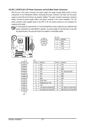
To meet expansion requirements, it is turned off and all the components on the motherboard. Before connecting the power connector, first make sure the power supply is recommended that a power supply that does not provide the required power, the result ...
To meet expansion requirements, it is turned off and all the components on the motherboard. Before connecting the power connector, first make sure the power supply is recommended that a power supply that does not provide the required power, the result ...
Manual
Page 23
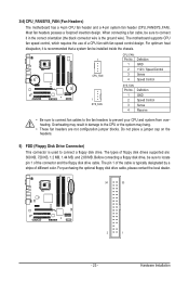
... 33 2 1 - 23 - The pin 1 of the connector and the floppy disk drive cable. 3/4) CPU_FAN/SYS_FAN (Fan Headers) The motherboard has a 4-pin CPU fan header and a 4-pin system fan header (CPU_FAN/SYS_FAN). The motherboard supports CPU fan speed control, which requires the use of floppy disk drives supported are not configuration jumper blocks...
... 33 2 1 - 23 - The pin 1 of the connector and the floppy disk drive cable. 3/4) CPU_FAN/SYS_FAN (Fan Headers) The motherboard has a 4-pin CPU fan header and a 4-pin system fan header (CPU_FAN/SYS_FAN). The motherboard supports CPU fan speed control, which requires the use of floppy disk drives supported are not configuration jumper blocks...

Manual
Page 26
Incorrect connection between the module connector and the motherboard header will be present on both of the front and back panel audio connections simultaneously. Definition 1 MIC 2 GND 3 MIC Power 4 NC 5 Line Out (R) 6 NC 7 NC 8 ... HD audio by default. If your chassis provides an AC'97 front panel audio module, refer to the instructions on each wire instead of the motherboard header. For information about connecting the front panel audio module that has different wire assignments, please contact the chassis manufacturer. 10) CD_IN (CD In Connector...
Incorrect connection between the module connector and the motherboard header will be present on both of the front and back panel audio connections simultaneously. Definition 1 MIC 2 GND 3 MIC Power 4 NC 5 Line Out (R) 6 NC 7 NC 8 ... HD audio by default. If your chassis provides an AC'97 front panel audio module, refer to the instructions on each wire instead of the motherboard header. For information about connecting the front panel audio module that has different wire assignments, please contact the chassis manufacturer. 10) CD_IN (CD In Connector...


