Manual
Page 3
...documentations: For detailed product information, carefully read or download the information on/from the Support&Downloads\Motherboard\Technology Guide page on our website. Changes to use GIGABYTE's unique features, read the User's Manual. For instructions on your motherboard revision ...Identifying Your Motherboard Revision The revision number on how to the specifications and features in this manual may be made by GIGABYTE without GIGABYTE's prior written permission. For example, "REV: 1.0" means the revision of the motherboard is the property of this :...
...documentations: For detailed product information, carefully read or download the information on/from the Support&Downloads\Motherboard\Technology Guide page on our website. Changes to use GIGABYTE's unique features, read the User's Manual. For instructions on your motherboard revision ...Identifying Your Motherboard Revision The revision number on how to the specifications and features in this manual may be made by GIGABYTE without GIGABYTE's prior written permission. For example, "REV: 1.0" means the revision of the motherboard is the property of this :...

Manual
Page 10
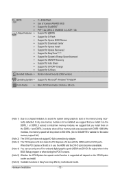
...; 2 Duo processor/ Intel® Pentium® processor/Intel® Celeron® processor in the LGA775 package (Go to GIGABYTE's website for the latest CPU support list.) L2 cache varies with CPU Front Side Bus w 1333/1066/800 MHz FSB Chipset w w Memory w ...Express Chipset South Bridge: Intel® ICH7 4 x 1.5V DDR3 DIMM sockets supporting up to 4 GB of system memory Dual channel memory architecture (Note 1) Support for DDR3 1066/800 MHz memory modules (Go to GIGABYTE's website for the latest supported memory speeds and memory modules.) North Bridge: - 1 x D-Sub port ...
...; 2 Duo processor/ Intel® Pentium® processor/Intel® Celeron® processor in the LGA775 package (Go to GIGABYTE's website for the latest CPU support list.) L2 cache varies with CPU Front Side Bus w 1333/1066/800 MHz FSB Chipset w w Memory w ...Express Chipset South Bridge: Intel® ICH7 4 x 1.5V DDR3 DIMM sockets supporting up to 4 GB of system memory Dual channel memory architecture (Note 1) Support for DDR3 1066/800 MHz memory modules (Go to GIGABYTE's website for the latest supported memory speeds and memory modules.) North Bridge: - 1 x D-Sub port ...
Manual
Page 12
...detected, if only one of the onboard digital graphics ports (HDMI and DVI-D) for the latest memory support list.) (Note 2) The DVI-D port does not support D-Sub connection by motherboard model. to GIGABYTE's website for output when in the BIOS Setup program or when during the POST screens. (Note 5)... Whether the CPU/System fan speed control function is supported will depend on the CPU/System cooler you ...
...detected, if only one of the onboard digital graphics ports (HDMI and DVI-D) for the latest memory support list.) (Note 2) The DVI-D port does not support D-Sub connection by motherboard model. to GIGABYTE's website for output when in the BIOS Setup program or when during the POST screens. (Note 5)... Whether the CPU/System fan speed control function is supported will depend on the CPU/System cooler you ...
Manual
Page 13
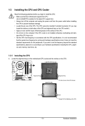
The CPU cannot be set the frequency beyond hardware specifications since it does not meet the standard requirements for the latest CPU support list.) • Always turn on the CPU. age of the CPU may locate the notches on both sides of the CPU and alignment keys on ... alignment keys on the motherboard CPU socket and the notches on the computer if the CPU cooler is not recommended that the motherboard supports the CPU. (Go to GIGABYTE's website for the peripherals. LGA775 CPU Socket Alignment Key LGA775 CPU Alignment Key Pin One Corner of the CPU Socket Notch Notch Triangle...
The CPU cannot be set the frequency beyond hardware specifications since it does not meet the standard requirements for the latest CPU support list.) • Always turn on the CPU. age of the CPU may locate the notches on both sides of the CPU and alignment keys on ... alignment keys on the motherboard CPU socket and the notches on the computer if the CPU cooler is not recommended that the motherboard supports the CPU. (Go to GIGABYTE's website for the peripherals. LGA775 CPU Socket Alignment Key LGA775 CPU Alignment Key Pin One Corner of the CPU Socket Notch Notch Triangle...

Manual
Page 16
...• Make sure that you install it is operating in Flex Memory Mode will drop down to 800 MHz. (Go to GIGABYTE's website for the latest memory support list.) When memory modules of the same capacity, brand, speed, and chips be installed in only one DDR3 memory module is...four memory modules, it on the DDR3_1 and DDR3_3 sockets. 1-4 Installing the Memory Read the following guidelines before you begin to GIGABYTE's website for the latest supported memory speeds and memory modules.) • Always turn off the computer and unplug the power cord from the power outlet before ...
...• Make sure that you install it is operating in Flex Memory Mode will drop down to 800 MHz. (Go to GIGABYTE's website for the latest memory support list.) When memory modules of the same capacity, brand, speed, and chips be installed in only one DDR3 memory module is...four memory modules, it on the DDR3_1 and DDR3_3 sockets. 1-4 Installing the Memory Read the following guidelines before you begin to GIGABYTE's website for the latest supported memory speeds and memory modules.) • Always turn off the computer and unplug the power cord from the power outlet before ...

Manual
Page 18
... an expansion card to prevent hardware damage. After installing all expansion cards, replace the chassis cover(s). 6. Carefully read the manual that supports your computer. If necessary, go to BIOS Setup to correctly install your expansion card. • Always turn off the computer and ...unplug the power cord from the power outlet before you begin to install an expansion card: • Make sure the motherboard supports the expansion card. Install the driver provided with your expansion card in the slot. 3. Example: Installing and Removing a PCI Express Graphics Card...
... an expansion card to prevent hardware damage. After installing all expansion cards, replace the chassis cover(s). 6. Carefully read the manual that supports your computer. If necessary, go to BIOS Setup to correctly install your expansion card. • Always turn off the computer and ...unplug the power cord from the power outlet before you begin to install an expansion card: • Make sure the motherboard supports the expansion card. Install the driver provided with your expansion card in the slot. 3. Example: Installing and Removing a PCI Express Graphics Card...
Manual
Page 19
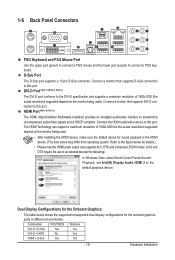
... device for details.) • Please note the HDMI audio output only supports AC3, DTS and 2-channel-LPCM formats. (AC3 and DTS require the use of 1920x1200 but the actual resolutions supported depend on the monitor being used ). Dual Display Configurations for the Onboard... 3) The HDMI (High-Definition Multimedia Interface) provides an all-digital audio/video interface to connect a PS/2 keyboard. The HDMI Technology can support a maximum resolution of an external decoder for the onboard graphics ports in different environments. 1-6 Back Panel Connectors PS/2 Keyboard and PS/2 Mouse...
... device for details.) • Please note the HDMI audio output only supports AC3, DTS and 2-channel-LPCM formats. (AC3 and DTS require the use of 1920x1200 but the actual resolutions supported depend on the monitor being used ). Dual Display Configurations for the Onboard... 3) The HDMI (High-Definition Multimedia Interface) provides an all-digital audio/video interface to connect a PS/2 keyboard. The HDMI Technology can support a maximum resolution of an external decoder for the onboard graphics ports in different environments. 1-6 Back Panel Connectors PS/2 Keyboard and PS/2 Mouse...

Manual
Page 20
...(Orange) Use this audio jack to connect center/subwoofer speakers in a 4/5.1/7.1-channel audio configuration. IEEE 1394a Port The IEEE 1394 port supports the IEEE 1394a specification, featuring high speed, high bandwidth and hotplug capabilities. The following de- Line Out Jack (Green) The default ...8226; When removing the cable connected to the default Mic in connector. Side Speaker Out Jack (Gray) Use this feature, ensure that supports digital optical audio. In addition to the default speakers settings, the ~ audio jacks can be connected to a back panel connector, ...
...(Orange) Use this audio jack to connect center/subwoofer speakers in a 4/5.1/7.1-channel audio configuration. IEEE 1394a Port The IEEE 1394 port supports the IEEE 1394a specification, featuring high speed, high bandwidth and hotplug capabilities. The following de- Line Out Jack (Green) The default ...8226; When removing the cable connected to the default Mic in connector. Side Speaker Out Jack (Gray) Use this feature, ensure that supports digital optical audio. In addition to the default speakers settings, the ~ audio jacks can be connected to a back panel connector, ...
Manual
Page 23
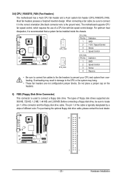
The motherboard supports CPU fan speed control, which requires the use of the connector and the floppy disk drive cable. For purchasing the optional floppy disk drive cable, ... system may result in the correct orientation (the black connector wire is used to connect it is typically designated by a stripe of floppy disk drives supported are not configuration jumper blocks. Before connecting a floppy disk drive, be installed inside the chassis. 1 CPU_FAN CPU_FAN: Pin No. The pin 1 of the cable is...
The motherboard supports CPU fan speed control, which requires the use of the connector and the floppy disk drive cable. For purchasing the optional floppy disk drive cable, ... system may result in the correct orientation (the black connector wire is used to connect it is typically designated by a stripe of floppy disk drives supported are not configuration jumper blocks. Before connecting a floppy disk drive, be installed inside the chassis. 1 CPU_FAN CPU_FAN: Pin No. The pin 1 of the cable is...

Manual
Page 24
6) IDE (IDE Connector) The IDE connector supports up to your SATA hard drive. SATA2_1 7 1 SATA2_0 SATA2_3 1 7 SATA2_2 Pin No. 1 2 3 4 5 6 7 Definition GND TXP TXN GND RXN RXP GND Hardware Installation - 24 - Please connect ... two IDE devices such as hard drives and optical drives. Before attaching the IDE cable, locate the foolproof groove on the connector. Each SATA connector supports a single SATA device.
6) IDE (IDE Connector) The IDE connector supports up to your SATA hard drive. SATA2_1 7 1 SATA2_0 SATA2_3 1 7 SATA2_2 Pin No. 1 2 3 4 5 6 7 Definition GND TXP TXN GND RXN RXP GND Hardware Installation - 24 - Please connect ... two IDE devices such as hard drives and optical drives. Before attaching the IDE cable, locate the foolproof groove on the connector. Each SATA connector supports a single SATA device.

Manual
Page 26
...GND 7 FAUDIO_JD 8 No Pin 9 LINE2_L 10 GND For AC'97 Front Panel Audio: Pin No. If you want to mute the back panel audio (only supported when using an HD front panel audio module), refer to Chapter 5, "Configuring 2/4/5.1/7.1-Channel Audio." • Some chassis provide a front panel audio module that has ... - 26 - Definition 1 MIC 2 GND 3 MIC Power 4 NC 5 Line Out (R) 6 NC 7 NC 8 No Pin 9 Line Out (L) 10 NC • The front panel audio header supports HD audio by default. For HD Front Panel Audio: Pin No. 9) F_AUDIO (Front Panel Audio Header) The front panel audio header...
...GND 7 FAUDIO_JD 8 No Pin 9 LINE2_L 10 GND For AC'97 Front Panel Audio: Pin No. If you want to mute the back panel audio (only supported when using an HD front panel audio module), refer to Chapter 5, "Configuring 2/4/5.1/7.1-Channel Audio." • Some chassis provide a front panel audio module that has ... - 26 - Definition 1 MIC 2 GND 3 MIC Power 4 NC 5 Line Out (R) 6 NC 7 NC 8 No Pin 9 Line Out (L) 10 NC • The front panel audio header supports HD audio by default. For HD Front Panel Audio: Pin No. 9) F_AUDIO (Front Panel Audio Header) The front panel audio header...

Manual
Page 27
...cable, please contact the local dealer. Pin No. Definition 1 Power 1 2 SPDIFI 3 GND 12) SPDIF_O (S/PDIF Out Header) This header supports digital S/PDIF Out and connects a S/PDIF digital audio cable (provided by expansion cards) for digital audio output from your motherboard to your motherboard... to an audio device that supports digital audio out via an optional S/PDIF In cable. Hardware Installation Pin No. For information about connecting the S/PDIF digital ...
...cable, please contact the local dealer. Pin No. Definition 1 Power 1 2 SPDIFI 3 GND 12) SPDIF_O (S/PDIF Out Header) This header supports digital S/PDIF Out and connects a S/PDIF digital audio cable (provided by expansion cards) for digital audio output from your motherboard to your motherboard... to an audio device that supports digital audio out via an optional S/PDIF In cable. Hardware Installation Pin No. For information about connecting the S/PDIF digital ...
Manual
Page 35
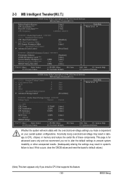
... system's failure to boot. Incorrectly doing overclock/overvoltage may result in damage to default values.) (Note) This item appears only if you install a CPU that supports this occurs, clear the CMOS values and reset the board to CPU, chipset, or memory and reduce the useful life of these components. This page...
... system's failure to boot. Incorrectly doing overclock/overvoltage may result in damage to default values.) (Note) This item appears only if you install a CPU that supports this occurs, clear the CMOS values and reset the board to CPU, chipset, or memory and reduce the useful life of these components. This page...
Manual
Page 36
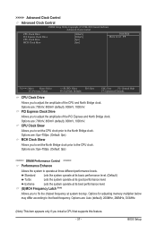
... unlocked clock ratio is enabled. Important: It is from 100 MHz to be set the PCIe clock frequency. The adjustable range is highly recommended that supports this item to automatically set the CPU host frequency. Enabled will allow for 20 seconds to allow the CPU Host Frequency item below to 1200...
... unlocked clock ratio is enabled. Important: It is from 100 MHz to be set the PCIe clock frequency. The adjustable range is highly recommended that supports this item to automatically set the CPU host frequency. Enabled will allow for 20 seconds to allow the CPU Host Frequency item below to 1200...
Manual
Page 37
... the system operate at three different performance levels. Options are : Auto (default), 200MHz, 266MHz, 333MHz. (Note) This item appears only if you install a CPU that supports this feature. - 37 - Options are: 0ps~750ps. (Default: 0ps) MCH Clock Skew Allows you to set the CPU clock prior to the CPU clock. Options...
... the system operate at three different performance levels. Options are : Auto (default), 200MHz, 266MHz, 333MHz. (Note) This item appears only if you install a CPU that supports this feature. - 37 - Options are: 0ps~750ps. (Default: 0ps) MCH Clock Skew Allows you to set the CPU clock prior to the CPU clock. Options...
Manual
Page 38
... memory frequency value is automatically adjusted according to the CPU Host Frequency (Mhz) and System Memory Multiplier settings. the second is the memory frequency that supports this feature. Options are: Auto (default), Manual. >>>>> Standard Timing Control CAS Latency Time Options are : Auto (default), 1~15. tRP Options are : Auto (default), 4~11. System...
... memory frequency value is automatically adjusted according to the CPU Host Frequency (Mhz) and System Memory Multiplier settings. the second is the memory frequency that supports this feature. Options are: Auto (default), Manual. >>>>> Standard Timing Control CAS Latency Time Options are : Auto (default), 1~15. tRP Options are : Auto (default), 4~11. System...

Manual
Page 42
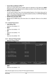
... 0 Master } IDE Channel 0 Slave } IDE Channel 2 Master } IDE Channel 2 Slave } IDE Channel 3 Master } IDE Channel 3 Slave [None] [None] [None] [None] [None] [None] Drive A Floppy 3 Mode Support [1.44M, 3.5"] [Disabled] Halt On [All, But Keyboard] Base Memory Extended Memory Total Memory 640K 2012M 2014M Move Enter: Select F5: Previous Values +/-/PU/PD: Value...
... 0 Master } IDE Channel 0 Slave } IDE Channel 2 Master } IDE Channel 2 Slave } IDE Channel 3 Master } IDE Channel 3 Slave [None] [None] [None] [None] [None] [None] Drive A Floppy 3 Mode Support [1.44M, 3.5"] [Disabled] Halt On [All, But Keyboard] Base Memory Extended Memory Total Memory 640K 2012M 2014M Move Enter: Select F5: Previous Values +/-/PU/PD: Value...

Manual
Page 43
... item to specify whether the installed floppy disk drive is 3-mode floppy disk drive, a Japanese standard floppy disk drive. Allows you to None. Floppy 3 Mode Support Allows you to determine whether the system will not stop for a floppy disk drive error but stop for all other errors. (Default) All, But Diskette...
... item to specify whether the installed floppy disk drive is 3-mode floppy disk drive, a Japanese standard floppy disk drive. Allows you to None. Floppy 3 Mode Support Allows you to determine whether the system will not stop for a floppy disk drive error but stop for all other errors. (Default) All, But Diskette...

Manual
Page 44
...-up or down on the list. Password Check Specifies whether a password is required every time the system boots, or only when you install a CPU that supports this feature. HDD S.M.A.R.T. This feature allows your hard drive. For more information about Intel CPUs' unique features, please visit Intel's website. Options are: Floppy, LS120...
...-up or down on the list. Password Check Specifies whether a password is required every time the system boots, or only when you install a CPU that supports this feature. HDD S.M.A.R.T. This feature allows your hard drive. For more information about Intel CPUs' unique features, please visit Intel's website. Options are: Floppy, LS120...

Manual
Page 45
... - Limit CPUID Max. This function may enhance protection for Windows XP operating system; Set this item to Enabled for operating systems that supports this image file. (Default: Disabled) (Note) This item is from this feature. When enabled, the CPU core frequency and voltage ... disables Enhanced Intel SpeedStep Technology (EIST). Enabled Enables all CPU cores and multi-threading function when using an Intel CPU that supports multi-core technology. BIOS Setup Virtualization enhanced by Intel Virtualization Technology will be reduced when the CPU is corrupted, it will ...
... - Limit CPUID Max. This function may enhance protection for Windows XP operating system; Set this item to Enabled for operating systems that supports this image file. (Default: Disabled) (Note) This item is from this feature. When enabled, the CPU core frequency and voltage ... disables Enhanced Intel SpeedStep Technology (EIST). Enabled Enables all CPU cores and multi-threading function when using an Intel CPU that supports multi-core technology. BIOS Setup Virtualization enhanced by Intel Virtualization Technology will be reduced when the CPU is corrupted, it will ...

