Manual
Page 1
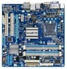
GA-EG41MF-US2H LGA775 socket motherboard for Intel® CoreTM processor family/ Intel® Pentium® processor family/Intel® Celeron® processor family User's Manual Rev. 1101 12ME-EG41MFU2H-1101R
GA-EG41MF-US2H LGA775 socket motherboard for Intel® CoreTM processor family/ Intel® Pentium® processor family/Intel® Celeron® processor family User's Manual Rev. 1101 12ME-EG41MFU2H-1101R
Manual
Page 2
Motherboard GA-EG41MF-US2H Mar. 20, 2009 Motherboard GA-EG41MF-US2H Mar. 20, 2009
Motherboard GA-EG41MF-US2H Mar. 20, 2009 Motherboard GA-EG41MF-US2H Mar. 20, 2009
Manual
Page 3
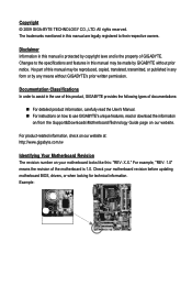
... the property of this manual may be made by GIGABYTE without GIGABYTE's prior written permission. Example: For product-related information, check on our website at: http://www.gigabyte.com.tw Identifying Your Motherboard Revision The revision number on your motherboard revision before updating motherboard BIOS, drivers, or when looking for technical information. Documentation Classifications In order...
... the property of this manual may be made by GIGABYTE without GIGABYTE's prior written permission. Example: For product-related information, check on our website at: http://www.gigabyte.com.tw Identifying Your Motherboard Revision The revision number on your motherboard revision before updating motherboard BIOS, drivers, or when looking for technical information. Documentation Classifications In order...
Manual
Page 4
Table of Contents Box Contents ...6 Optional Items...6 GA-EG41MF-US2H Motherboard Layout 7 Block Diagram...8 Chapter 1 Hardware Installation 9 1-1 Installation Precautions 9 1-2 Product Specifications 10 1-3 Installing the CPU and CPU Cooler 13 1-3-1 Installing the CPU 13 1-3-2 Installing the CPU ...
Table of Contents Box Contents ...6 Optional Items...6 GA-EG41MF-US2H Motherboard Layout 7 Block Diagram...8 Chapter 1 Hardware Installation 9 1-1 Installation Precautions 9 1-2 Product Specifications 10 1-3 Installing the CPU and CPU Cooler 13 1-3-1 Installing the CPU 13 1-3-2 Installing the CPU ...
Manual
Page 6
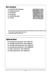
Box Contents GA-EG41MF-US2H motherboard Motherboard driver disk User's Manual One IDE cable Two SATA 3Gb/s cables I/O Shield • The box contents above are subject to change without notice. • The motherboard image is for reference only and the actual items shall depend on the product package you obtain. The box contents are for reference only...
Box Contents GA-EG41MF-US2H motherboard Motherboard driver disk User's Manual One IDE cable Two SATA 3Gb/s cables I/O Shield • The box contents above are subject to change without notice. • The motherboard image is for reference only and the actual items shall depend on the product package you obtain. The box contents are for reference only...
Manual
Page 7
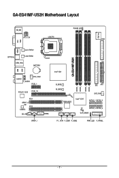
GA-EG41MF-US2H Motherboard Layout KB_MS PHASE LED IT8718 ATX_12V LGA775 FDD VGA LAN DVI HDMI Level Shifter OPTICAL Level Shifter USB_1394 BATTERY USB AUDIO F_AUDIO CPU_FAN PCIE_1 RTL8111C/D PCIE_16 PCI1 SPDIF_O PCI2 CODEC CD_IN SPDIF_I COMA GA-EG41MF-US2H Intel® G41 B_BIOS M_BIOS TSB43AB23 Intel® ICH7 DDR2_1 DDR2_2 DDR2_3 DDR2_4 IDE ATX SYS_FAN SATA2_1 SATA2_3 CI SATA2_0 SATA2_2 CLR_CMOS F1_1394 F_USB1 F_USB2 PWR_LED F_PANEL - 7 -
GA-EG41MF-US2H Motherboard Layout KB_MS PHASE LED IT8718 ATX_12V LGA775 FDD VGA LAN DVI HDMI Level Shifter OPTICAL Level Shifter USB_1394 BATTERY USB AUDIO F_AUDIO CPU_FAN PCIE_1 RTL8111C/D PCIE_16 PCI1 SPDIF_O PCI2 CODEC CD_IN SPDIF_I COMA GA-EG41MF-US2H Intel® G41 B_BIOS M_BIOS TSB43AB23 Intel® ICH7 DDR2_1 DDR2_2 DDR2_3 DDR2_4 IDE ATX SYS_FAN SATA2_1 SATA2_3 CI SATA2_0 SATA2_2 CLR_CMOS F1_1394 F_USB1 F_USB2 PWR_LED F_PANEL - 7 -
Manual
Page 9
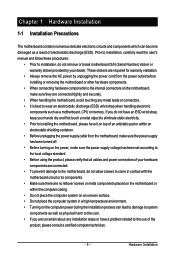
...wear an electrostatic discharge (ESD) wrist strap when handling electronic components such as a motherboard, CPU or memory. Chapter 1 Hardware Installation 1-1 Installation Precautions The motherboard contains numerous delicate electronic circuits and components which can lead to damage to system components ..., please consult a certified computer technician. - 9 - These stickers are connected tightly and securely. • When handling the motherboard, avoid touching any installation steps or have it on top of an antistatic pad or within an electrostatic shielding container. •...
...wear an electrostatic discharge (ESD) wrist strap when handling electronic components such as a motherboard, CPU or memory. Chapter 1 Hardware Installation 1-1 Installation Precautions The motherboard contains numerous delicate electronic circuits and components which can lead to damage to system components ..., please consult a certified computer technician. - 9 - These stickers are connected tightly and securely. • When handling the motherboard, avoid touching any installation steps or have it on top of an antistatic pad or within an electrostatic shielding container. •...

Manual
Page 10
... supporting up to 8 GB of system memory (Note 1) Dual channel memory architecture (Note 2) Support for DDR2 800/667 MHz memory modules (Go to GIGABYTE's website for the latest memory support list.) North Bridge: - 1 x D-Sub port - 1 x DVI-D port (Note 3) (Note 4) - 1 x HDMI port (... Bridge Up to 8 USB 2.0/1.1 ports (4 on the back panel, 1 via the USB brackets connected to the internal IEEE 1394a header) GA-EG41MF-US2H Motherboard - 10 - TSB43AB23 chip Up to 2 IEEE 1394a ports (1 on the back panel, 4 via the IEEE 1394a bracket connected to the...
... supporting up to 8 GB of system memory (Note 1) Dual channel memory architecture (Note 2) Support for DDR2 800/667 MHz memory modules (Go to GIGABYTE's website for the latest memory support list.) North Bridge: - 1 x D-Sub port - 1 x DVI-D port (Note 3) (Note 4) - 1 x HDMI port (... Bridge Up to 8 USB 2.0/1.1 ports (4 on the back panel, 1 via the USB brackets connected to the internal IEEE 1394a header) GA-EG41MF-US2H Motherboard - 10 - TSB43AB23 chip Up to 2 IEEE 1394a ports (1 on the back panel, 4 via the IEEE 1394a bracket connected to the...

Manual
Page 12
to install two memory modules, we suggest that you install them on the DDR2_1 or DDR2_3 socket; GA-EG41MF-US2H Motherboard - 12 - When the PCI Express x16 slot is in EasyTune may differ by adapter. (Note 4)... memory module is supported will depend on the CPU/ System cooler you install it on the DDR2_1 and DDR2_3 sockets. (Go to GIGABYTE's website for Microsoft® Windows® 7/Vista/XP Micro ATX Form Factor; 24.4cm x 24.4cm (Note 1)...61559; Support for the latest memory support list.) (Note 3) The DVI-D port does not support D-Sub connection by motherboard model.
to install two memory modules, we suggest that you install them on the DDR2_1 or DDR2_3 socket; GA-EG41MF-US2H Motherboard - 12 - When the PCI Express x16 slot is in EasyTune may differ by adapter. (Note 4)... memory module is supported will depend on the CPU/ System cooler you install it on the DDR2_1 and DDR2_3 sockets. (Go to GIGABYTE's website for Microsoft® Windows® 7/Vista/XP Micro ATX Form Factor; 24.4cm x 24.4cm (Note 1)...61559; Support for the latest memory support list.) (Note 3) The DVI-D port does not support D-Sub connection by motherboard model.
Manual
Page 13
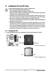
mended that the motherboard supports the CPU. (Go to GIGABYTE's website for the peripherals. LGA775 CPU Socket Alignment Key LGA 775 CPU Alignment Key Pin One Corner of the CPU Socket Notch Notch Triangle Pin ... do so according to your hardware specifications including the CPU, graphics card, memory, hard drive, etc. 1-3-1 Installing the CPU A. Locate the alignment keys on the motherboard CPU socket and the notches on the CPU - 13 - If you may occur. • Set the CPU host frequency in accordance with the CPU specifications...
mended that the motherboard supports the CPU. (Go to GIGABYTE's website for the peripherals. LGA775 CPU Socket Alignment Key LGA 775 CPU Alignment Key Pin One Corner of the CPU Socket Notch Notch Triangle Pin ... do so according to your hardware specifications including the CPU, graphics card, memory, hard drive, etc. 1-3-1 Installing the CPU A. Locate the alignment keys on the motherboard CPU socket and the notches on the CPU - 13 - If you may occur. • Set the CPU host frequency in accordance with the CPU specifications...

Manual
Page 14
... replace the protective socket cover when the CPU is properly inserted, replace the load plate and push the CPU socket lever back into the motherboard CPU socket. GA-EG41MF-US2H Motherboard - 14 - Step 2: Lift the metal load plate from the CPU socket. (DO NOT touch socket contacts.) Step 3: Remove the protective socket cover from the...
... replace the protective socket cover when the CPU is properly inserted, replace the load plate and push the CPU socket lever back into the motherboard CPU socket. GA-EG41MF-US2H Motherboard - 14 - Step 2: Lift the metal load plate from the CPU socket. (DO NOT touch socket contacts.) Step 3: Remove the protective socket cover from the...
Manual
Page 15
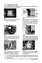
.... If the push pin is inserted as the example cooler.) Step 1: Apply an even and thin layer of thermal grease on the surface of the motherboard. Check that the Male and Female push pins are joined closely. (Refer to the CPU. Inadequately removing the CPU cooler may adhere to your CPU... direction of the CPU cooler to install.) Step 3: Place the cooler atop the CPU, aligning the four push pins through the pin holes on the motherboard. Step 6: Finally, attach the power connector of arrow is to remove the cooler, on the contrary, is to the CPU fan header (CPU_FAN) on the...
.... If the push pin is inserted as the example cooler.) Step 1: Apply an even and thin layer of thermal grease on the surface of the motherboard. Check that the Male and Female push pins are joined closely. (Refer to the CPU. Inadequately removing the CPU cooler may adhere to your CPU... direction of the CPU cooler to install.) Step 3: Place the cooler atop the CPU, aligning the four push pins through the pin holes on the motherboard. Step 6: Finally, attach the power connector of arrow is to remove the cooler, on the contrary, is to the CPU fan header (CPU_FAN) on the...

Manual
Page 16
... chips be enabled if only one direction. After the memory is recommended that memory of different capacity and chips are unable to GIGABYTE's website for optimum performance. 3. DS/SS - - - - GA-EG41MF-US2H Motherboard - 16 - Enabling Dual Channel memory mode will automatically detect the specifications and capacity of the same capacity, brand, speed, and chips be...
... chips be enabled if only one direction. After the memory is recommended that memory of different capacity and chips are unable to GIGABYTE's website for optimum performance. 3. DS/SS - - - - GA-EG41MF-US2H Motherboard - 16 - Enabling Dual Channel memory mode will automatically detect the specifications and capacity of the same capacity, brand, speed, and chips be...
Manual
Page 17
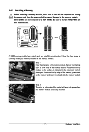
Place the memory module on this motherboard. Notch DDR2 DIMM A DDR2 memory module has a notch, so it vertically into place when the memory module is securely inserted. - 17 - Spread the retaining clips ...
Place the memory module on this motherboard. Notch DDR2 DIMM A DDR2 memory module has a notch, so it vertically into place when the memory module is securely inserted. - 17 - Spread the retaining clips ...

Manual
Page 18
... Removing the Card: Gently push back on the lever on the card are completely inserted into the PCI Express x16 slot. GA-EG41MF-US2H Motherboard - 18 - 1-5 Installing an Expansion Card Read the following guidelines before installing an expansion card to make any required BIOS ...Locate an expansion slot that came with your computer. Secure the card's metal bracket to install an expansion card: • Make sure the motherboard supports the expansion card. Install the driver provided with a screw. 5. Example: Installing and Removing a PCI Express Graphics Card: •...
... Removing the Card: Gently push back on the lever on the card are completely inserted into the PCI Express x16 slot. GA-EG41MF-US2H Motherboard - 18 - 1-5 Installing an Expansion Card Read the following guidelines before installing an expansion card to make any required BIOS ...Locate an expansion slot that came with your computer. Secure the card's metal bracket to install an expansion card: • Make sure the motherboard supports the expansion card. Install the driver provided with a screw. 5. Example: Installing and Removing a PCI Express Graphics Card: •...

Manual
Page 19
... DVI-D ports. Connect the HDMI audio/ video device to a back panel connector, first remove the cable from your device and then remove it from the motherboard. • When removing the cable, pull it side to side to connect a PS/2 keyboard. HDMI Port The HDMI (High-Definition Multimedia Interface) provides an all...
... DVI-D ports. Connect the HDMI audio/ video device to a back panel connector, first remove the cable from your device and then remove it from the motherboard. • When removing the cable, pull it side to side to connect a PS/2 keyboard. HDMI Port The HDMI (High-Definition Multimedia Interface) provides an all...

Manual
Page 20
...GB DDR2 800 memory modules with dual channel mode enabled • Playback software: CyberLink PowerDVD 8.0 or later (Note: Please ensure Hardware Acceleration is occurring GA-EG41MF-US2H Motherboard - 20 - Note that supports digital optical audio. Playback of the LAN port LEDs. In addition, under this port for USB devices such as ...this configuration, the BIOS Setup and POST screens can only be output from the HDMI port. A. Dual Display Configurations: This motherboard provides three display ports, DVI-D, HDMI, and D-Sub ports and supports dualdisplay configurations.
...GB DDR2 800 memory modules with dual channel mode enabled • Playback software: CyberLink PowerDVD 8.0 or later (Note: Please ensure Hardware Acceleration is occurring GA-EG41MF-US2H Motherboard - 20 - Note that supports digital optical audio. Playback of the LAN port LEDs. In addition, under this port for USB devices such as ...this configuration, the BIOS Setup and POST screens can only be output from the HDMI port. A. Dual Display Configurations: This motherboard provides three display ports, DVI-D, HDMI, and D-Sub ports and supports dualdisplay configurations.

Manual
Page 22
... devices and your devices are compliant with the connectors you wish to connect. • Before installing the devices, be sure to the connector on the motherboard. GA-EG41MF-US2H Motherboard - 22 - 1-7 Internal Connectors 1 20 5 9 3 2 11 6 4 7 14 12 19 13 17 16 15 18 8 10 1) ATX_12V 2) ATX 3) CPU_FAN 4) SYS_FAN 5) FDD 6) IDE 7) SATA2_0/1/2/3 8) PWR_LED 9) BATTERY 10) F_PANEL...
... devices and your devices are compliant with the connectors you wish to connect. • Before installing the devices, be sure to the connector on the motherboard. GA-EG41MF-US2H Motherboard - 22 - 1-7 Internal Connectors 1 20 5 9 3 2 11 6 4 7 14 12 19 13 17 16 15 18 8 10 1) ATX_12V 2) ATX 3) CPU_FAN 4) SYS_FAN 5) FDD 6) IDE 7) SATA2_0/1/2/3 8) PWR_LED 9) BATTERY 10) F_PANEL...
Manual
Page 23
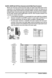
... be used that can lead to an unstable or unbootable system. • The main power connector is turned off and all the components on the motherboard. When using a 2x10 power supply. 3 4 1 2 ATX_12V ATX_12V: Pin No. 1 2 3 4 Definition GND GND +12V +12V 12 24 1 13 ATX ATX: Pin No. 1 2 3 4 5 6 7... cable into pins under the protective cover when using a 2x12 power supply, remove the protective cover from the main power connector on the motherboard. If a power supply is used (500W or greater). 1/2) ATX_12V/ATX (2x2 12V Power Connector and 2x12 Main Power Connector) With ...
... be used that can lead to an unstable or unbootable system. • The main power connector is turned off and all the components on the motherboard. When using a 2x10 power supply. 3 4 1 2 ATX_12V ATX_12V: Pin No. 1 2 3 4 Definition GND GND +12V +12V 12 24 1 13 ATX ATX: Pin No. 1 2 3 4 5 6 7... cable into pins under the protective cover when using a 2x12 power supply, remove the protective cover from the main power connector on the motherboard. If a power supply is used (500W or greater). 1/2) ATX_12V/ATX (2x2 12V Power Connector and 2x12 Main Power Connector) With ...

Manual
Page 24
...Connector) This connector is used to prevent your CPU and system from overheating. The pin 1 of the cable is the ground wire). The motherboard supports CPU fan speed control, which requires the use of different color. Overheating may hang. • These fan headers are : 360 KB... with fan speed control design. For purchasing the optional floppy disk drive cable, please contact the local dealer. 34 33 2 1 GA-EG41MF-US2H Motherboard - 24 - 3/4) CPU_FAN/SYS_FAN (Fan Headers) The motherboard has a 4-pin CPU fan header and a 4-pin system fan header (CPU_FAN/ SYS_FAN).
...Connector) This connector is used to prevent your CPU and system from overheating. The pin 1 of the cable is the ground wire). The motherboard supports CPU fan speed control, which requires the use of different color. Overheating may hang. • These fan headers are : 360 KB... with fan speed control design. For purchasing the optional floppy disk drive cable, please contact the local dealer. 34 33 2 1 GA-EG41MF-US2H Motherboard - 24 - 3/4) CPU_FAN/SYS_FAN (Fan Headers) The motherboard has a 4-pin CPU fan header and a 4-pin system fan header (CPU_FAN/ SYS_FAN).


