
Manual
Page 4
Table of Contents Box Contents ...6 OptionalItems ...6 GA-EG41M-S2H/S2 Motherboard Layout 7 Block Diagram ...8 Chapter 1 Hardware Installation 9 1-1 Installation Precautions 9 1-2 Product Specifications 10 1-3 Installing the CPU and CPU ...Memory 17 1-5 Installing an Expansion Card 18 1-6 Back Panel Connectors 21 1-7 Internal Connectors 23 Chapter 2 BIOS Setup 35 2-1 Startup Screen 36 2-2 The Main Menu 37 2-3 MB Intelligent Tweaker(M.I.T 39 2-4 Standard CMOS Features 46 2-5 Advanced BIOS Features 48 2-6 Advanced Chipset Features 50 2-7 IntegratedPeripherals 52 2-8 Power Management...
Table of Contents Box Contents ...6 OptionalItems ...6 GA-EG41M-S2H/S2 Motherboard Layout 7 Block Diagram ...8 Chapter 1 Hardware Installation 9 1-1 Installation Precautions 9 1-2 Product Specifications 10 1-3 Installing the CPU and CPU ...Memory 17 1-5 Installing an Expansion Card 18 1-6 Back Panel Connectors 21 1-7 Internal Connectors 23 Chapter 2 BIOS Setup 35 2-1 Startup Screen 36 2-2 The Main Menu 37 2-3 MB Intelligent Tweaker(M.I.T 39 2-4 Standard CMOS Features 46 2-5 Advanced BIOS Features 48 2-6 Advanced Chipset Features 50 2-7 IntegratedPeripherals 52 2-8 Power Management...
Manual
Page 11
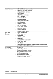
Hardware Installation Internal Connectors 1 x 24-pin ATX main power connector 1 x 4-pin ATX 12V power connector 1 x floppy disk drive connector 1 x IDE connector 4 x SATA 3Gb/s connectors 1 x CPU fan header 1 x ... CPU/System fan speed detection CPU overheating warning CPU/System fan fail warning CPU/System fan speed control (Note 3) * Only for GA-EG41M-S2H. - 11 -
Hardware Installation Internal Connectors 1 x 24-pin ATX main power connector 1 x 4-pin ATX 12V power connector 1 x floppy disk drive connector 1 x IDE connector 4 x SATA 3Gb/s connectors 1 x CPU fan header 1 x ... CPU/System fan speed detection CPU overheating warning CPU/System fan fail warning CPU/System fan speed control (Note 3) * Only for GA-EG41M-S2H. - 11 -
Manual
Page 24
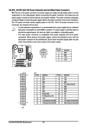
...2x12-pin ATX) GND (Only for 2x12-pin ATX) GA-EG41M-S2H/S2 Motherboard - 24 - Do not insert the power supply cable into pins under the protective cover when using a 2x12 power supply, remove the protective cover from the main power connector on the motherboard. Connect the power supply cable ...to an unstable or unbootable system. • The main power connector is turned off and all the components on the motherboard. If a ...
...2x12-pin ATX) GND (Only for 2x12-pin ATX) GA-EG41M-S2H/S2 Motherboard - 24 - Do not insert the power supply cable into pins under the protective cover when using a 2x12 power supply, remove the protective cover from the main power connector on the motherboard. Connect the power supply cable ...to an unstable or unbootable system. • The main power connector is turned off and all the components on the motherboard. If a ...

Manual
Page 28
... front panel to this header, make sure the wire assignments and the pin assignments are matched correctly. The LED is on the chassis front panel. GA-EG41M-S2H/S2 Motherboard - 28 - Refer to Chapter 5, "Troubleshooting," for more information). • SPEAK (Speaker, Orange): Connects to indicate the problem. ...may issue beeps in S3/S4/S5 Off S3/S4 sleep state or powered off when the system is operating. A front panel module mainly consists of power switch, reset switch, power LED, hard drive activity LED, speaker and etc. When connecting your system using the ...
... front panel to this header, make sure the wire assignments and the pin assignments are matched correctly. The LED is on the chassis front panel. GA-EG41M-S2H/S2 Motherboard - 28 - Refer to Chapter 5, "Troubleshooting," for more information). • SPEAK (Speaker, Orange): Connects to indicate the problem. ...may issue beeps in S3/S4/S5 Off S3/S4 sleep state or powered off when the system is operating. A front panel module mainly consists of power switch, reset switch, power LED, hard drive activity LED, speaker and etc. When connecting your system using the ...
Manual
Page 35
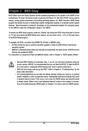
... up BIOS without entering the operating system. • @BIOS is recommended that you not flash the BIOS. To upgrade the BIOS, use either the GIGABYTE Q-Flash or @BIOS utility. • Q-Flash allows the user to keep the configuration values in the CMOS on using the current version of the ...to) to activate certain system features. For instructions on the motherboard. To see more advanced BIOS Setup menu options, you can press + in the main menu of the battery/clearing CMOS jumper in this occurs, try to clear the CMOS values and reset the board to default values. (Refer to...
... up BIOS without entering the operating system. • @BIOS is recommended that you not flash the BIOS. To upgrade the BIOS, use either the GIGABYTE Q-Flash or @BIOS utility. • Q-Flash allows the user to keep the configuration values in the CMOS on using the current version of the ...to) to activate certain system features. For instructions on the motherboard. To see more advanced BIOS Setup menu options, you can press + in the main menu of the battery/clearing CMOS jumper in this occurs, try to clear the CMOS values and reset the board to default values. (Refer to...

Manual
Page 37
Use arrow keys to move among the items and press to accept or enter a sub-menu. (Sample BIOS Version: GA-EG41M-S2H D1) CMOS Setup Utility-Copyright (C) 1984-2008 Award Software MB Intelligent Tweaker(M.I.T.) Standard CMOS Features Advanced BIOS Features...Change CPU's Clock & Voltage BIOS Setup Program Function Keys Move the selection bar to select an item Execute command or enter the submenu Main Menu: Exit the BIOS Setup program Submenus: Exit current submenu Increase the numeric value or make changes Decrease the numeric value or make...
Use arrow keys to move among the items and press to accept or enter a sub-menu. (Sample BIOS Version: GA-EG41M-S2H D1) CMOS Setup Utility-Copyright (C) 1984-2008 Award Software MB Intelligent Tweaker(M.I.T.) Standard CMOS Features Advanced BIOS Features...Change CPU's Clock & Voltage BIOS Setup Program Function Keys Move the selection bar to select an item Execute command or enter the submenu Main Menu: Exit the BIOS Setup program Submenus: Exit current submenu Increase the numeric value or make changes Decrease the numeric value or make...
Manual
Page 38
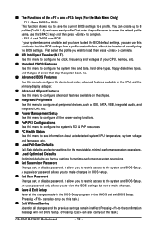
The Functions of the and keys (For the Main Menu Only) F11 : Save CMOS to BIOS This function allows you to save the current BIOS settings to the system and BIOS Setup. It ... 8 profiles (Profile 1-8) and name each profile. You can create up to the confirmation message will exit BIOS Setup. (Pressing can also carry out this task.) GA-EG41M-S2H/S2 Motherboard - 38 - An user password only allows you to the system and BIOS Setup.
The Functions of the and keys (For the Main Menu Only) F11 : Save CMOS to BIOS This function allows you to save the current BIOS settings to the system and BIOS Setup. It ... 8 profiles (Profile 1-8) and name each profile. You can create up to the confirmation message will exit BIOS Setup. (Pressing can also carry out this task.) GA-EG41M-S2H/S2 Motherboard - 38 - An user password only allows you to the system and BIOS Setup.
Manual
Page 48
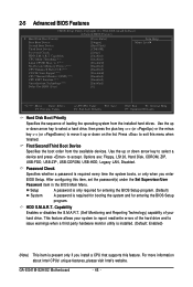
... a hard drive, then press the plus key (or ) or the minus key (or ) to move it up or down on the list. GA-EG41M-S2H/S2 Motherboard - 48 - Press to accept. After configuring this menu when finished. For more information about Intel CPUs' unique features, please visit Intel's...key to select a device and press to exit this item, set the password(s) under the Set Supervisor/User Password item in the BIOS Main Menu. Capability Enables or disables the S.M.A.R.T. (Self Monitoring and Reporting Technology) capability of your system to issue warnings when a third party ...
... a hard drive, then press the plus key (or ) or the minus key (or ) to move it up or down on the list. GA-EG41M-S2H/S2 Motherboard - 48 - Press to accept. After configuring this menu when finished. For more information about Intel CPUs' unique features, please visit Intel's...key to select a device and press to exit this item, set the password(s) under the Set Supervisor/User Password item in the BIOS Main Menu. Capability Enables or disables the S.M.A.R.T. (Self Monitoring and Reporting Technology) capability of your system to issue warnings when a third party ...

Manual
Page 61
... F12: Load CMOS from BIOS Save Data to CMOS Press on this item and press the key. Press or to return to the BIOS Setup Main Menu. 2-15 Exit Without Saving CMOS Setup Utility-Copyright (C) 1984-2008 Award Software MB Intelligent Tweaker(M.I .T.) PC Health Status Standard CMOS Features... Setup PnP/PCI Configurations Exit Without Saving ESC: Quit F8: Q-Flash Select Item F10: Save & Exit Setup F11: Save CMOS to the BIOS Setup Main Menu. - 61 -
... F12: Load CMOS from BIOS Save Data to CMOS Press on this item and press the key. Press or to return to the BIOS Setup Main Menu. 2-15 Exit Without Saving CMOS Setup Utility-Copyright (C) 1984-2008 Award Software MB Intelligent Tweaker(M.I .T.) PC Health Status Standard CMOS Features... Setup PnP/PCI Configurations Exit Without Saving ESC: Quit F8: Q-Flash Select Item F10: Save & Exit Setup F11: Save CMOS to the BIOS Setup Main Menu. - 61 -
Manual
Page 72
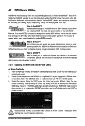
.... From GIGABYTE's website, download the latest compressed BIOS update file that support DualBIOS have two BIOS onboard, a main BIOS and a backup BIOS. Note: The USB flash drive or hard drive must use and allow you from the nearest @BIOS server site and update the BIOS. 4-2-1 Updating the BIOS with caution. GA-EG41M-S2H/S2 Motherboard...
.... From GIGABYTE's website, download the latest compressed BIOS update file that support DualBIOS have two BIOS onboard, a main BIOS and a backup BIOS. Note: The USB flash drive or hard drive must use and allow you from the nearest @BIOS server site and update the BIOS. 4-2-1 Updating the BIOS with caution. GA-EG41M-S2H/S2 Motherboard...
Manual
Page 73
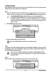
...Step 2: The process of Q-Flash, use the up or down arrow key to select Update BIOS from Drive and press . • The Save Main BIOS to Drive option allows you to save the BIOS file to Drive Please:Mproevses any key to return to update BIOS?" ... is displayed on the screen. B. Insert the floppy disk containing the BIOS file into the floppy disk drive. appears, press to access Q-Flash. 2. In the main menu of the system reading the BIOS file from Drive Sa0vefilBeI(Os)SfotounDdrive :Move ESC:Reset :Power Off Total size : 0 Free size : 0 3. ...
...Step 2: The process of Q-Flash, use the up or down arrow key to select Update BIOS from Drive and press . • The Save Main BIOS to Drive option allows you to save the BIOS file to Drive Please:Mproevses any key to return to update BIOS?" ... is displayed on the screen. B. Insert the floppy disk containing the BIOS file into the floppy disk drive. appears, press to access Q-Flash. 2. In the main menu of the system reading the BIOS file from Drive Sa0vefilBeI(Os)SfotounDdrive :Move ESC:Reset :Power Off Total size : 0 Free size : 0 3. ...
Manual
Page 87
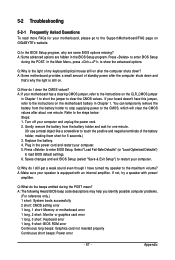
Q:In the BIOS Setup program, why are hidden in Chapter 1 to short the jumper to enter BIOS Setup during the POST mean? In the Main Menu, press + to load BIOS default settings. 6. Select "Load Fail-Safe Defaults" (or "Load Optimized Defaults") to show the advanced options. A: ... the CMOS values. A: Some motherboard provides a small amount of standby power after the computer shuts down and that's why the light is still on GIGABYTE's website. Turn off your speaker is the light of the battery holder, making them short for 5 seconds.) 3. A: Make sure your computer and ...
Q:In the BIOS Setup program, why are hidden in Chapter 1 to short the jumper to enter BIOS Setup during the POST mean? In the Main Menu, press + to load BIOS default settings. 6. Select "Load Fail-Safe Defaults" (or "Load Optimized Defaults") to show the advanced options. A: ... the CMOS values. A: Some motherboard provides a small amount of standby power after the computer shuts down and that's why the light is still on GIGABYTE's website. Turn off your speaker is the light of the battery holder, making them short for 5 seconds.) 3. A: Make sure your computer and ...

Manual
Page 88
START Turn off the power. Make sure the motherboard does not short-circuit with the chassis or other metal objects. Connect the ATX main power cable and the 12V power cable. Turn on the CPU. Connect the CPU cooler power cable to enter BIOS Setup. The...Insert the graphics card. Secure the CPU No cooler on the power to solve the problem. The problem is verified and solved. A (Continued...) GA-EG41M-S2H/S2 Motherboard - 88 - 5-2-2 Troubleshooting Procedure If you encounter any troubles during system startup, follow the troubleshooting procedure below to start the computer.
START Turn off the power. Make sure the motherboard does not short-circuit with the chassis or other metal objects. Connect the ATX main power cable and the 12V power cable. Turn on the CPU. Connect the CPU cooler power cable to enter BIOS Setup. The...Insert the graphics card. Secure the CPU No cooler on the power to solve the problem. The problem is verified and solved. A (Continued...) GA-EG41M-S2H/S2 Motherboard - 88 - 5-2-2 Troubleshooting Procedure If you encounter any troubles during system startup, follow the troubleshooting procedure below to start the computer.