Manual
Page 3
...laws and is 1.0. Changes to assist in the use GIGABYTE's unique features, read or download the information on/from the Support\Motherboard\Technology Guide page on your motherboard revision before updating motherboard BIOS, drivers, or when looking for technical information. For ...product-related information, check on our website at: http://www.gigabyte.com.tw Identifying Your Motherboard Revision The revision number on our...
...laws and is 1.0. Changes to assist in the use GIGABYTE's unique features, read or download the information on/from the Support\Motherboard\Technology Guide page on your motherboard revision before updating motherboard BIOS, drivers, or when looking for technical information. For ...product-related information, check on our website at: http://www.gigabyte.com.tw Identifying Your Motherboard Revision The revision number on our...
Manual
Page 4
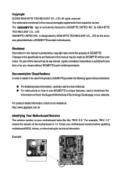
Table of Contents Box Contents ...6 OptionalItems...6 GA-EG31M-S2 Motherboard Layout 7 Block Diagram...8 Chapter 1 Hardware Installation 9 1-1 Installation Precautions 9 1-2 Product Specifications 10 1-3 Installing the CPU and CPU Cooler 12 ... Memory 16 1-5 Installing an Expansion Card 17 1-6 Back Panel Connectors 18 1-7 Internal Connectors 20 Chapter 2 BIOS Setup 31 2-1 Startup Screen 32 2-2 The Main Menu 33 2-3 Standard CMOS Features 35 2-4 Advanced BIOS Features 37 2-5 IntegratedPeripherals 39 2-6 Power Management Setup 42 2-7 PnP/PCI Configurations 44 2-8 PC Health Status ...
Table of Contents Box Contents ...6 OptionalItems...6 GA-EG31M-S2 Motherboard Layout 7 Block Diagram...8 Chapter 1 Hardware Installation 9 1-1 Installation Precautions 9 1-2 Product Specifications 10 1-3 Installing the CPU and CPU Cooler 12 ... Memory 16 1-5 Installing an Expansion Card 17 1-6 Back Panel Connectors 18 1-7 Internal Connectors 20 Chapter 2 BIOS Setup 31 2-1 Startup Screen 32 2-2 The Main Menu 33 2-3 Standard CMOS Features 35 2-4 Advanced BIOS Features 37 2-5 IntegratedPeripherals 39 2-6 Power Management Setup 42 2-7 PnP/PCI Configurations 44 2-8 PC Health Status ...
Manual
Page 5
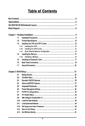
... 54 3-3 Technical Manuals 54 3-4 Contact ...55 3-5 System ...55 3-6 Download Center 56 Chapter 4 Unique Features 57 4-1 Xpress Recovery2 57 4-2 BIOS Update Utilities 62 4-2-1 Updating the BIOS with the Q-Flash Utility 62 4-2-2 Updating the BIOS with the @BIOS Utility 65 4-3 EasyTune 5 Pro 66 4-4 Dynamic Energy Saver Advanced 67 Chapter 5 Appendix ...69 5-1 Configuring Audio Input and Output...
... 54 3-3 Technical Manuals 54 3-4 Contact ...55 3-5 System ...55 3-6 Download Center 56 Chapter 4 Unique Features 57 4-1 Xpress Recovery2 57 4-2 BIOS Update Utilities 62 4-2-1 Updating the BIOS with the Q-Flash Utility 62 4-2-2 Updating the BIOS with the @BIOS Utility 65 4-3 EasyTune 5 Pro 66 4-4 Dynamic Energy Saver Advanced 67 Chapter 5 Appendix ...69 5-1 Configuring Audio Input and Output...
Manual
Page 8
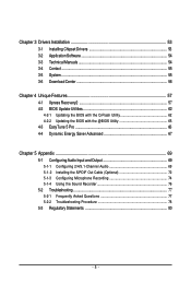
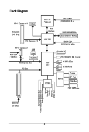
Block Diagram 1 PCI Express x16 D-Sub PCIe CLK (100 MHz) PCI Express x16 1 PCI Express x1 LAN PCIe CLK (100 MHz) x1 RJ45 RTL8111C PCI Express Bus PCI Bus LGA775 Processor Host Interface Intel® G31 CPU CLK+/(333/266/200 MHz) DDR2 800/667 MHz Dual Channel Memory GMCH CLK (333/266/200 MHz) Intel® ICH7 CODEC Dual BIOS ATA-100/66/33 IDE Channel 4 SATA 3Gb/s 8 USB Ports IT8718 Floppy LPT Port COM Port PS/2 KB/Mouse 2 PCI PCI CLK (33 MHz) Surround Speaker Out Center/Subwoofer Speaker Out Side Speaker Out MIC Line-Out Line-In SPDIF In SPDIF Out - 8 -
Block Diagram 1 PCI Express x16 D-Sub PCIe CLK (100 MHz) PCI Express x16 1 PCI Express x1 LAN PCIe CLK (100 MHz) x1 RJ45 RTL8111C PCI Express Bus PCI Bus LGA775 Processor Host Interface Intel® G31 CPU CLK+/(333/266/200 MHz) DDR2 800/667 MHz Dual Channel Memory GMCH CLK (333/266/200 MHz) Intel® ICH7 CODEC Dual BIOS ATA-100/66/33 IDE Channel 4 SATA 3Gb/s 8 USB Ports IT8718 Floppy LPT Port COM Port PS/2 KB/Mouse 2 PCI PCI CLK (33 MHz) Surround Speaker Out Center/Subwoofer Speaker Out Side Speaker Out MIC Line-Out Line-In SPDIF In SPDIF Out - 8 -
Manual
Page 11
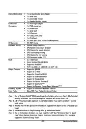
... fail warning Š CPU fan speed control (Note 3) BIOS Š 2 x 8 Mbit flash Š Use of licensed AWARD BIOS Š Support for DualBIOSTM Š PnP 1.0a, DMI 2.0, SM BIOS 2.4, ACPI 1.0b Unique Features Š Support for @BIOS Š Support for Q-Flash Š Support for Virtual Dual BIOS Š Support for Download Center Š Support for Xpress...
... fail warning Š CPU fan speed control (Note 3) BIOS Š 2 x 8 Mbit flash Š Use of licensed AWARD BIOS Š Support for DualBIOSTM Š PnP 1.0a, DMI 2.0, SM BIOS 2.4, ACPI 1.0b Unique Features Š Support for @BIOS Š Support for Q-Flash Š Support for Virtual Dual BIOS Š Support for Download Center Š Support for Xpress...
Manual
Page 15
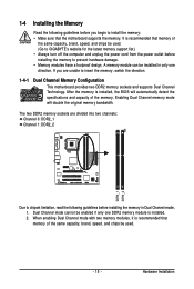
...mode with two memory modules, it is recommended that memory of the same capacity, brand, speed, and chips be used . (Go to GIGABYTE's website for the latest memory support list.) • Always turn off the computer and unplug the power cord from the power outlet before installing... the memory in only one DDR2 memory module is installed, the BIOS will double the original memory bandwidth. 1-4 Installing the Memory Read the following guidelines before you are divided into two channels: Channel 0: DDR2_1...
...mode with two memory modules, it is recommended that memory of the same capacity, brand, speed, and chips be used . (Go to GIGABYTE's website for the latest memory support list.) • Always turn off the computer and unplug the power cord from the power outlet before installing... the memory in only one DDR2 memory module is installed, the BIOS will double the original memory bandwidth. 1-4 Installing the Memory Read the following guidelines before you are divided into two channels: Channel 0: DDR2_1...
Manual
Page 17
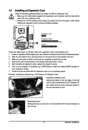
... inserted into the PCI Express x16 slot. Make sure the card is fully seated in the expansion slot. 1. If necessary, go to BIOS Setup to make any required BIOS changes for your computer. Carefully read the manual that supports your operating system. PCI Express x1 Slot PCI Express x16 Slot PCI Slot...
... inserted into the PCI Express x16 slot. Make sure the card is fully seated in the expansion slot. 1. If necessary, go to BIOS Setup to make any required BIOS changes for your computer. Carefully read the manual that supports your operating system. PCI Express x1 Slot PCI Express x16 Slot PCI Slot...
Manual
Page 24
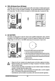
... negative terminals of the battery (the positive side should face up). • Used batteries must be handled in S3/S4 sleep state or powered off . GA-EG31M-S2 Motherboard - 24 - Replace the battery. 4. Gently remove the battery from the battery holder and wait for 5 seconds.) 3. Pin No. 1 2 3 Definition ... System Status LED S0 On S1 Blinking S3/S4/S5 Off 9) BAT (BATTERY) The battery provides power to keep the values (such as BIOS configurations, date, and time information) in S1 sleep state. Replace the battery when the battery voltage drops to a low level, or the ...
... negative terminals of the battery (the positive side should face up). • Used batteries must be handled in S3/S4 sleep state or powered off . GA-EG31M-S2 Motherboard - 24 - Replace the battery. 4. Gently remove the battery from the battery holder and wait for 5 seconds.) 3. Pin No. 1 2 3 Definition ... System Status LED S0 On S1 Blinking S3/S4/S5 Off 9) BAT (BATTERY) The battery provides power to keep the values (such as BIOS configurations, date, and time information) in S1 sleep state. Replace the battery when the battery voltage drops to a low level, or the ...
Manual
Page 25
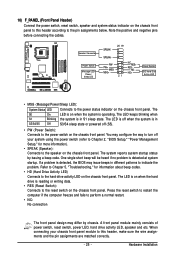
...• SPEAK (Speaker): Connects to the reset switch on the chassis front panel. When connecting your system using the power switch (refer to Chapter 2, "BIOS Setup," "Power Management Setup," for information about beep codes. • HD (Hard Drive Activity LED) Connects to the pin assignments below. HDHD+ Reset... to this header according to the hard drive activity LED on the chassis front panel. The LED is off when the system is detected, the BIOS may configure the way to turn off (S5). • PW (Power Switch): Connects to perform a normal restart. • NC: No ...
...• SPEAK (Speaker): Connects to the reset switch on the chassis front panel. When connecting your system using the power switch (refer to Chapter 2, "BIOS Setup," "Power Management Setup," for information about beep codes. • HD (Hard Drive Activity LED) Connects to the pin assignments below. HDHD+ Reset... to this header according to the hard drive activity LED on the chassis front panel. The LED is off when the system is detected, the BIOS may configure the way to turn off (S5). • PW (Power Switch): Connects to perform a normal restart. • NC: No ...
Manual
Page 29
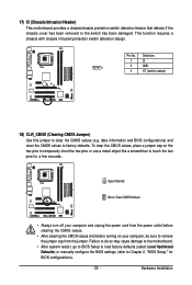
...few seconds. Failure to do so may cause damage to the motherboard. • After system restart, go to BIOS Setup to load factory defaults (select Load Optimized Defaults) or manually configure the BIOS settings (refer to factory defaults. To clear the CMOS values, place a jumper cap on your computer, be ...sure to touch the two pins for BIOS configurations). - 29 - Open: Normal Short: Clear CMOS Values • Always turn off your computer and unplug the power cord from the power ...
...few seconds. Failure to do so may cause damage to the motherboard. • After system restart, go to BIOS Setup to load factory defaults (select Load Optimized Defaults) or manually configure the BIOS settings (refer to factory defaults. To clear the CMOS values, place a jumper cap on your computer, be ...sure to touch the two pins for BIOS configurations). - 29 - Open: Normal Short: Clear CMOS Values • Always turn off your computer and unplug the power cord from the power ...
Manual
Page 31
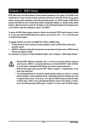
... key during system startup, saving system parameters and loading operating system, etc. To upgrade the BIOS, use either the GIGABYTE Q-Flash or @BIOS utility. • Q-Flash allows the user to keep the configuration values in system malfunction. • BIOS will emit a beep code during the POST. For instructions on the motherboard supplies the necessary...
... key during system startup, saving system parameters and loading operating system, etc. To upgrade the BIOS, use either the GIGABYTE Q-Flash or @BIOS utility. • Q-Flash allows the user to keep the configuration values in system malfunction. • BIOS will emit a beep code during the POST. For instructions on the motherboard supplies the necessary...
Manual
Page 32
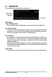
GA-EG31M-S2 Motherboard - 32 - Note: The setting in Boot Menu. In Boot Menu, use the up hard...the POST. To exit Boot Menu, press . The system will still be used for one time only. EG31M-S2 ED1 . . . . : BIOS Setup/Q-Flash : XpressRecovery2 : Boot Menu : Qflash 07/17/2008-G31-ICH7-6A99OG0BC-00 Function Keys Function Keys...: : BIOS Setup/Q-Flash Press the key to enter BIOS Setup or to access the Q-Flash utility in BIOS Setup. : Xpress Recovery2 If you to set the first boot device without having to...
GA-EG31M-S2 Motherboard - 32 - Note: The setting in Boot Menu. In Boot Menu, use the up hard...the POST. To exit Boot Menu, press . The system will still be used for one time only. EG31M-S2 ED1 . . . . : BIOS Setup/Q-Flash : XpressRecovery2 : Boot Menu : Qflash 07/17/2008-G31-ICH7-6A99OG0BC-00 Function Keys Function Keys...: : BIOS Setup/Q-Flash Press the key to enter BIOS Setup or to access the Q-Flash utility in BIOS Setup. : Xpress Recovery2 If you to set the first boot device without having to...
Manual
Page 33
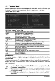
... keys available for the current submenus Access the Q-Flash utility Display system information Save all the changes and exit the BIOS Setup program Save CMOS to display a help screen. BIOS Setup BIOS Setup Program Function Keys Move the selection bar to select an item Execute command or enter the submenu Main Menu: ... While in the Item Help block on the right side of the submenu. • If you do not find the settings you enter the BIOS Setup program, the Main Menu (as usual, select the Load Optimized Defaults item to set your system to its defaults. • The...
... keys available for the current submenus Access the Q-Flash utility Display system information Save all the changes and exit the BIOS Setup program Save CMOS to display a help screen. BIOS Setup BIOS Setup Program Function Keys Move the selection bar to select an item Execute command or enter the submenu Main Menu: ... While in the Item Help block on the right side of the submenu. • If you do not find the settings you enter the BIOS Setup program, the Main Menu (as usual, select the Load Optimized Defaults item to set your system to its defaults. • The...
Manual
Page 34
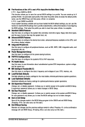
... configure all peripheral devices, such as IDE, SATA, USB, integrated audio, and integrated LAN, etc. „ Power Management Setup Use this task.) GA-EG31M-S2 Motherboard - 34 - Pressing to the confirmation message will exit BIOS Setup. (Pressing can create up to 8 profiles (Profile 1-8) and name each profile. It allows you to save the current...
... configure all peripheral devices, such as IDE, SATA, USB, integrated audio, and integrated LAN, etc. „ Power Management Setup Use this task.) GA-EG31M-S2 Motherboard - 34 - Pressing to the confirmation message will exit BIOS Setup. (Pressing can create up to 8 profiles (Profile 1-8) and name each profile. It allows you to save the current...
Manual
Page 35
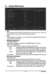
... None so the system will Access Mode skip the detection of the two methods below : • Auto • None • Manual Lets BIOS automatically detect IDE/SATA devices during the POST for faster system startup. IDE Channel 0 Master/Slave Configure your IDE/SATA devices by using one of... of the IDE/SATA device on this item to manually enter the specifications of the three methods below : • Auto • None Lets BIOS automatically detect IDE/SATA devices during the POST for faster system startup. 2-3 Standard CMOS Features Date (mm:dd:yy) Time (hh:mm:ss)...
... None so the system will Access Mode skip the detection of the two methods below : • Auto • None • Manual Lets BIOS automatically detect IDE/SATA devices during the POST for faster system startup. IDE Channel 0 Master/Slave Configure your IDE/SATA devices by using one of... of the IDE/SATA device on this item to manually enter the specifications of the three methods below : • Auto • None Lets BIOS automatically detect IDE/SATA devices during the POST for faster system startup. 2-3 Standard CMOS Features Date (mm:dd:yy) Time (hh:mm:ss)...
Manual
Page 36
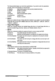
...But Disk/Key The system boot will not stop for a keyboard or a floppy disk drive error but it will not stop for any error. GA-EG31M-S2 Motherboard - 36 - Landing Zone Landing zone. Options are : Disabled (default), Drive A. Halt On Allows you to selects the type of floppy ... 1.44M/3.5", 2.88M/3.5". Memory These fields are read-only and are determined by the BIOS POST. Base Memory Also called conventional memory. Total Memory The total amount of cylinders. All Errors Whenever the BIOS detects a non-fatal error the system boot will stop for an error during the ...
...But Disk/Key The system boot will not stop for a keyboard or a floppy disk drive error but it will not stop for any error. GA-EG31M-S2 Motherboard - 36 - Landing Zone Landing zone. Options are : Disabled (default), Drive A. Halt On Allows you to selects the type of floppy ... 1.44M/3.5", 2.88M/3.5". Memory These fields are read-only and are determined by the BIOS POST. Base Memory Also called conventional memory. Total Memory The total amount of cylinders. All Errors Whenever the BIOS detects a non-fatal error the system boot will stop for an error during the ...
Manual
Page 37
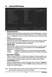
...of loading the operating system from the available devices. set the password(s) under the Set Supervisor/User Password item in the BIOS Main Menu. Capability Limit CPUID Max. After configuring this menu when finished. Capability Enables or disables the S.M.A.R.T. (Self Monitoring... and Reporting Technology) capability of your system to 3 (Note) Allows you enter BIOS Setup. HDD S.M.A.R.T. This feature allows your hard drive. Set this item to Disabled for legacy operating system such as Windows NT4.0. (Default...
...of loading the operating system from the available devices. set the password(s) under the Set Supervisor/User Password item in the BIOS Main Menu. Capability Limit CPUID Max. After configuring this menu when finished. Capability Enables or disables the S.M.A.R.T. (Self Monitoring... and Reporting Technology) capability of your system to 3 (Note) Allows you enter BIOS Setup. HDD S.M.A.R.T. This feature allows your hard drive. Set this item to Disabled for legacy operating system such as Windows NT4.0. (Default...
Manual
Page 39
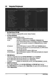
Auto Lets BIOS set to Combined. Non-Combined Sets all SATA devices to operate in SATA mode. Disabled Disables the integrated IDE controller when Non-Combined is dependent ... Sets the IDE channels to Ch. 0 Master/Slave. (Default) Ch.1 Master/Slave Sets the IDE channels to be automatically set to Combined or Enhanced mode. BIOS Setup SATA Port 0/2 Set to settings. Combined allows a maximum of 4 ATA devices to Ch. 1 Master/Slave. 2-5 Integrated Peripherals CMOS Setup Utility-Copyright (C) 1984-2008 Award...
Auto Lets BIOS set to Combined. Non-Combined Sets all SATA devices to operate in SATA mode. Disabled Disables the integrated IDE controller when Non-Combined is dependent ... Sets the IDE channels to Ch. 0 Master/Slave. (Default) Ch.1 Master/Slave Sets the IDE channels to be automatically set to Combined or Enhanced mode. BIOS Setup SATA Port 0/2 Set to settings. Combined allows a maximum of 4 ATA devices to Ch. 1 Master/Slave. 2-5 Integrated Peripherals CMOS Setup Utility-Copyright (C) 1984-2008 Award...
Manual
Page 41
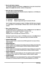
... its base I /O address and corresponding interrupt. Parallel Port Mode Selects an operating mode for the onboard parallel (LPT) port. If a cable problem occurs on Part 1-2. BIOS Setup Note: Part 4-5 and Part 7-8 are not used in a 10/100 Mbps environment, so their Status fields will be the approximate distance to the motherboard...
... its base I /O address and corresponding interrupt. Parallel Port Mode Selects an operating mode for the onboard parallel (LPT) port. If a cable problem occurs on Part 1-2. BIOS Setup Note: Part 4-5 and Part 7-8 are not used in a 10/100 Mbps environment, so their Status fields will be the approximate distance to the motherboard...
Manual
Page 43
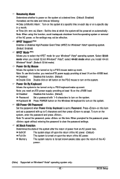
... the system to clear the password settings. select 64-bit mode when you need an ATX power supply providing at least 1A on the system. BIOS Setup Time (hh: mm: ss) Alarm : Set the time at which the system will be turned on by a PS/2 mouse wake-up to 5 characters and...
... the system to clear the password settings. select 64-bit mode when you need an ATX power supply providing at least 1A on the system. BIOS Setup Time (hh: mm: ss) Alarm : Set the time at which the system will be turned on by a PS/2 mouse wake-up to 5 characters and...


