
Manual
Page 4
... of Contents Box Contents...6 Optional Items...6 GA-D525TUD/GA-D425TUD Motherboard Layout 7 GA-D525TUD/GA-D425TUD Motherboard Block Diagram 8 Chapter 1 ...Hardware Installation 9 1-1 Installation Precautions 9 1-2 Product Specifications 10 1-3 Installing the Memory 12 1-4 Back Panel Connectors 13 1-5 Internal Connectors 15 Chapter 2 BIOS Setup 23 2-1 Startup Screen 24 2-2 The Main Menu 25 2-3 MB Intelligent Tweaker(M.I.T 27 2-4 Standard CMOS Features 29 2-5 Advanced BIOS Features 31 2-6 Integrated Peripherals 33 2-7 Power...
... of Contents Box Contents...6 Optional Items...6 GA-D525TUD/GA-D425TUD Motherboard Layout 7 GA-D525TUD/GA-D425TUD Motherboard Block Diagram 8 Chapter 1 ...Hardware Installation 9 1-1 Installation Precautions 9 1-2 Product Specifications 10 1-3 Installing the Memory 12 1-4 Back Panel Connectors 13 1-5 Internal Connectors 15 Chapter 2 BIOS Setup 23 2-1 Startup Screen 24 2-2 The Main Menu 25 2-3 MB Intelligent Tweaker(M.I.T 27 2-4 Standard CMOS Features 29 2-5 Advanced BIOS Features 31 2-6 Integrated Peripherals 33 2-7 Power...

Manual
Page 6
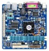
Optional Items 2-port USB 2.0 bracket (Part No. 12CR1-1UB030-5*R) 2-port SATA power cable (Part No. 12CF1-2SERPW-0*R) COM port cable (Part No. 12CF1-1CM001-3*R) - 6 - Box Contents GA-D525TUD or GA-D425TUD motherboard Motherboard driver disk User's Manual One IDE cable One SATA cable I/O Shield • The box contents above are subject to change without notice. • The motherboard image is for reference only and the actual items shall depend on the product package you obtain. The box contents are for reference only.
Optional Items 2-port USB 2.0 bracket (Part No. 12CR1-1UB030-5*R) 2-port SATA power cable (Part No. 12CF1-2SERPW-0*R) COM port cable (Part No. 12CF1-1CM001-3*R) - 6 - Box Contents GA-D525TUD or GA-D425TUD motherboard Motherboard driver disk User's Manual One IDE cable One SATA cable I/O Shield • The box contents above are subject to change without notice. • The motherboard image is for reference only and the actual items shall depend on the product package you obtain. The box contents are for reference only.

Manual
Page 9
... to eliminate static electricity. • Prior to installing the motherboard, please have a problem related to the internal connectors on the computer power during the installation process can become damaged as a result of the product, please consult a certified computer technician. - 9 - If ... or metal components placed on the motherboard or within an electrostatic shielding container. • Before unplugging the power supply cable from the power outlet before installing or removing the motherboard or other hardware components. • When connecting hardware components to the...
... to eliminate static electricity. • Prior to installing the motherboard, please have a problem related to the internal connectors on the computer power during the installation process can become damaged as a result of the product, please consult a certified computer technician. - 9 - If ... or metal components placed on the motherboard or within an electrostatic shielding container. • Before unplugging the power supply cable from the power outlet before installing or removing the motherboard or other hardware components. • When connecting hardware components to the...
Manual
Page 10
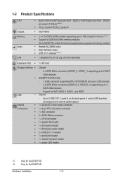
... x SATA 3Gb/s connectors (SATA2_0, SATA2_1) supporting up to 2 SATA 3Gb/s devices GIGABYTE SATA2 chip: - 1 x IDE connector supporting ATA-133/100/66/33 and up to 2 IDE...power connector Connectors w 1 x 4-pin ATX 12V power connector w 1 x IDE connector w 4 x SATA 3Gb/s connectors w 1 x CPU fan header w 1 x system fan header w 1 x front panel header w 1 x front panel audio header w 2 x USB 2.0/1.1 headers w 1 x serial port header w 1 x chassis intrusion header w 1 x power LED header j Only for GA-D525TUD...
... x SATA 3Gb/s connectors (SATA2_0, SATA2_1) supporting up to 2 SATA 3Gb/s devices GIGABYTE SATA2 chip: - 1 x IDE connector supporting ATA-133/100/66/33 and up to 2 IDE...power connector Connectors w 1 x 4-pin ATX 12V power connector w 1 x IDE connector w 4 x SATA 3Gb/s connectors w 1 x CPU fan header w 1 x system fan header w 1 x front panel header w 1 x front panel audio header w 2 x USB 2.0/1.1 headers w 1 x serial port header w 1 x chassis intrusion header w 1 x power LED header j Only for GA-D525TUD...
Manual
Page 12
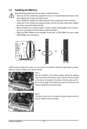
... memory, push down on the memory and insert it can be used. (Go to GIGABYTE's website for the latest supported memory speeds and memory modules.) • Always turn off the computer and unplug the power cord from the power outlet before you are unable to insert the memory, switch the direction. • DDR3...
... memory, push down on the memory and insert it can be used. (Go to GIGABYTE's website for the latest supported memory speeds and memory modules.) • Always turn off the computer and unplug the power cord from the power outlet before you are unable to insert the memory, switch the direction. • DDR3...

Manual
Page 15
... connectors you wish to connect. • Before installing the devices, be sure to the connector on the motherboard. - 15 - Hardware Installation Unplug the power cord from the power outlet to prevent damage to the devices. • After installing the device and before connecting external devices: • First make sure the device cable...
... connectors you wish to connect. • Before installing the devices, be sure to the connector on the motherboard. - 15 - Hardware Installation Unplug the power cord from the power outlet to prevent damage to the devices. • After installing the device and before connecting external devices: • First make sure the device cable...

Manual
Page 16
.... 3 4 1 2 ATX_12V ATX_12V: Pin No. 1 2 3 4 Definition GND GND +12V +12V 10 20 1 11 ATX ATX: Pin No. 1 2 3 4 5 6 7 8 9 10 Definition 3.3V 3.3V GND +5V GND +5V GND Power Good 5VSB (stand by +5V) +12V Pin No. 11 12 13 14 15 16 17 18 19 20 Definition 3.3V -12V GND PS_ON (soft On...
.... 3 4 1 2 ATX_12V ATX_12V: Pin No. 1 2 3 4 Definition GND GND +12V +12V 10 20 1 11 ATX ATX: Pin No. 1 2 3 4 5 6 7 8 9 10 Definition 3.3V 3.3V GND +5V GND +5V GND Power Good 5VSB (stand by +5V) +12V Pin No. 11 12 13 14 15 16 17 18 19 20 Definition 3.3V -12V GND PS_ON (soft On...

Manual
Page 19
... of the positive side (+) and the negative side (-) of the battery holder, making them short for one . You may be used to connect a system power LED on when the system is operating. The LED is off when the system is on the chassis to keep the values (such as BIOS...- Definition 1 MPD+ 2 MPD- 1 3 MPD- Gently remove the battery from the battery holder and wait for 5 seconds.) 3. The LED is in S3/S4 sleep state or powered off . Replace the battery. 4. The LED keeps blinking when the system is turned off (S5). System Status LED S0 On S1 Blinking S3/S4/S5...
... of the positive side (+) and the negative side (-) of the battery holder, making them short for one . You may be used to connect a system power LED on when the system is operating. The LED is off when the system is on the chassis to keep the values (such as BIOS...- Definition 1 MPD+ 2 MPD- 1 3 MPD- Gently remove the battery from the battery holder and wait for 5 seconds.) 3. The LED is in S3/S4 sleep state or powered off . Replace the battery. 4. The LED keeps blinking when the system is turned off (S5). System Status LED S0 On S1 Blinking S3/S4/S5...

Manual
Page 20
... Activity LED) Connects to the hard drive activity LED on when the system is in S1 sleep state. The LED keeps blinking when the sys- Power Switch Message/Power/ Sleep LED PWPW+ MSGMSG+ 10 9 NC RES+ RESHDHD+ 21 Reset Switch Hard Drive Activity LED • MSG/PWR (Message... freezes and fails to the pin assignments below. The LED S0 On is in S3/S4 sleep S3/S4/S5 Off state or powered off (S5). • PW (Power Switch): Connects to this header, make sure the wire assignments and the pin assignments are matched correctly. Note the positive and negative pins...
... Activity LED) Connects to the hard drive activity LED on when the system is in S1 sleep state. The LED keeps blinking when the sys- Power Switch Message/Power/ Sleep LED PWPW+ MSGMSG+ 10 9 NC RES+ RESHDHD+ 21 Reset Switch Hard Drive Activity LED • MSG/PWR (Message... freezes and fails to the pin assignments below. The LED S0 On is in S3/S4 sleep S3/S4/S5 Off state or powered off (S5). • PW (Power Switch): Connects to this header, make sure the wire assignments and the pin assignments are matched correctly. Note the positive and negative pins...

Manual
Page 21
... • Audio signals will make the device unable to work or even damage it. Definition 1 2 1 MIC2_L 1 MIC 2 GND 2 GND 9 10 3 MIC2_R 4 -ACZ_DET 3 MIC Power 4 NC 5 LINE2_R 5 Line Out (R) 6 GND 6 NC 7 FAUDIO_JD 7 NC 8 No Pin 8 No Pin 9 LINE2_L 9 Line Out (L) 10 GND 10 NC • The... 2.0/1.1 specification. For purchasing the optional USB bracket, please contact the local dealer. 10 9 2 1 Pin No. 1 2 3 4 5 6 7 8 9 10 Definition Power (5V) Power (5V) USB DXUSB DYUSB DX+ USB DY+ GND GND No Pin NC • Do not plug the IEEE 1394 bracket (2x5-pin) cable into the...
... • Audio signals will make the device unable to work or even damage it. Definition 1 2 1 MIC2_L 1 MIC 2 GND 2 GND 9 10 3 MIC2_R 4 -ACZ_DET 3 MIC Power 4 NC 5 LINE2_R 5 Line Out (R) 6 GND 6 NC 7 FAUDIO_JD 7 NC 8 No Pin 8 No Pin 9 LINE2_L 9 Line Out (L) 10 GND 10 NC • The... 2.0/1.1 specification. For purchasing the optional USB bracket, please contact the local dealer. 10 9 2 1 Pin No. 1 2 3 4 5 6 7 8 9 10 Definition Power (5V) Power (5V) USB DXUSB DYUSB DX+ USB DY+ GND GND No Pin NC • Do not plug the IEEE 1394 bracket (2x5-pin) cable into the...

Manual
Page 23
...altering the settings may result in Chapter 1 for the beep codes description. • It is turned on the motherboard supplies the necessary power to the CMOS to keep the configuration values in system's failure to prevent system instability or other unexpected results. If this chapter or ...it is turned off, the battery on . Inadequate BIOS flashing may result in the CMOS. BIOS Setup To upgrade the BIOS, use either the GIGABYTE Q-Flash or @BIOS utility. • Q-Flash allows the user to quickly and easily upgrade or back up BIOS without entering the operating system....
...altering the settings may result in Chapter 1 for the beep codes description. • It is turned on the motherboard supplies the necessary power to the CMOS to keep the configuration values in system's failure to prevent system instability or other unexpected results. If this chapter or ...it is turned off, the battery on . Inadequate BIOS flashing may result in the CMOS. BIOS Setup To upgrade the BIOS, use either the GIGABYTE Q-Flash or @BIOS utility. • Q-Flash allows the user to quickly and easily upgrade or back up BIOS without entering the operating system....

Manual
Page 25
... items and press to accept or enter a sub-menu. (Sample BIOS Version: GA-D525TUD E10c) CMOS Setup Utility-Copyright (C) 1984-2010 Award Software MB Intelligent Tweaker(M.I.T.) Standard CMOS Features Advanced BIOS Features Integrated Peripherals Power Management Setup PnP/PCI Configurations PC Health Status Load Fail-Safe...
... items and press to accept or enter a sub-menu. (Sample BIOS Version: GA-D525TUD E10c) CMOS Setup Utility-Copyright (C) 1984-2010 Award Software MB Intelligent Tweaker(M.I.T.) Standard CMOS Features Advanced BIOS Features Integrated Peripherals Power Management Setup PnP/PCI Configurations PC Health Status Load Fail-Safe...
Manual
Page 26
... Peripherals Use this menu to configure all peripheral devices, such as IDE, SATA, USB, integrated audio, and integrated LAN, etc. Power Management Setup Use this menu to configure all changes and the previous settings remain in effect. First select the profile you wish to load, then...without the hassles of reconfiguring the BIOS settings. It allows you can also carry out this task.) Exit Without Saving Abandon all the power-saving functions. PnP/PCI Configurations Use this menu to configure the system's PCI & PnP resources. PC Health Status Use ...
... Peripherals Use this menu to configure all peripheral devices, such as IDE, SATA, USB, integrated audio, and integrated LAN, etc. Power Management Setup Use this menu to configure all changes and the previous settings remain in effect. First select the profile you wish to load, then...without the hassles of reconfiguring the BIOS settings. It allows you can also carry out this task.) Exit Without Saving Abandon all the power-saving functions. PnP/PCI Configurations Use this menu to configure the system's PCI & PnP resources. PC Health Status Use ...
Manual
Page 36
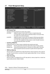
...) Supported on Suspend) sleep state. S1(POS) Enables the system to be resumed at least 1A on the +5VSB lead. (Default: Enabled) Power On by a wake-up signal from a PCI or PCIe device. The system can be awakened from an ACPI sleep state by Ring Allows the ... at any time. Soft-Off by Alarm x Date (of Month) Alarm x Time (hh:mm:ss) Alarm HPET Support (Note) HPET Mode (Note) Power On By Mouse Power On By Keyboard x KB Power ON Password AC Back Function ErP Support [S3(STR)] [Instant-Off] [Enabled] [Enabled] [Disabled] Everyday 0 : 0 : 0 [Enabled] [32-...
...) Supported on Suspend) sleep state. S1(POS) Enables the system to be resumed at least 1A on the +5VSB lead. (Default: Enabled) Power On by a wake-up signal from a PCI or PCIe device. The system can be awakened from an ACPI sleep state by Ring Allows the ... at any time. Soft-Off by Alarm x Date (of Month) Alarm x Time (hh:mm:ss) Alarm HPET Support (Note) HPET Mode (Note) Power On By Mouse Power On By Keyboard x KB Power ON Password AC Back Function ErP Support [S3(STR)] [Instant-Off] [Enabled] [Enabled] [Disabled] Everyday 0 : 0 : 0 [Enabled] [32-...

Manual
Page 37
... on the system. To turn on this function. (Default) Password Set a password with up event. Disabled Disables this item. Keyboard 98 Press POWER button on the Windows 98 keyboard to turn on the system. Press on this item is set a password with 1~5 characters to turn on by...entering the password to select the HPET mode for Windows 7/Vista operating system. (Default: Enabled) HPET Mode (Note) Allows you need an ATX power supply providing at a specific time on each day or on Windows 7/Vista operating system only. - 37 - AC Back Function Determines the state of...
... on the system. To turn on this function. (Default) Password Set a password with up event. Disabled Disables this item. Keyboard 98 Press POWER button on the Windows 98 keyboard to turn on the system. Press on this item is set a password with 1~5 characters to turn on by...entering the password to select the HPET mode for Windows 7/Vista operating system. (Default: Enabled) HPET Mode (Note) Allows you need an ATX power supply providing at a specific time on each day or on Windows 7/Vista operating system only. - 37 - AC Back Function Determines the state of...

Manual
Page 40
...Features Load Optimized Defaults Advanced BIOS Features Set Supervisor Password Integrated Peripherals Set User Password Power Management Setup PnP/PCI Configurations Save & Exit Setup Load Optimized Defa ul ts (Y/NE)?xiNt Without Saving ...CMOS Features Load Optimized Defaults Advanced BIOS Features Set Supervisor Password Integrated Peripherals Set User Password Power Management Setup PnP/PCI Configurations Save & Exit Setup Load Fail-Safe Defau lt s (Y/N)E?xNit Without Saving ...
...Features Load Optimized Defaults Advanced BIOS Features Set Supervisor Password Integrated Peripherals Set User Password Power Management Setup PnP/PCI Configurations Save & Exit Setup Load Optimized Defa ul ts (Y/NE)?xiNt Without Saving ...CMOS Features Load Optimized Defaults Advanced BIOS Features Set Supervisor Password Integrated Peripherals Set User Password Power Management Setup PnP/PCI Configurations Save & Exit Setup Load Fail-Safe Defau lt s (Y/N)E?xNit Without Saving ...

Manual
Page 41
... Password CMOS Setup Utility-Copyright (C) 1984-2010 Award Software MB Intelligent Tweaker(M.I.T.) Standard CMOS Features Advanced BIOS Features Integrated Peripherals Power Management Setup PnP/PCI Configurations Enter Password: PC Health Status Load Fail-Safe Defaults Load Optimized Defaults Set Supervisor Password Set User Password...
... Password CMOS Setup Utility-Copyright (C) 1984-2010 Award Software MB Intelligent Tweaker(M.I.T.) Standard CMOS Features Advanced BIOS Features Integrated Peripherals Power Management Setup PnP/PCI Configurations Enter Password: PC Health Status Load Fail-Safe Defaults Load Optimized Defaults Set Supervisor Password Set User Password...

Manual
Page 42
...Optimized Defaults Advanced BIOS Features Quit Without Savin g (Y/N)?SNet Supervisor Password Integrated Peripherals Set User Password Power Management Setup Save & Exit Setup PnP/PCI Configurations Exit Without Saving PC Health Status ESC: Quit F8:...; Advanced BIOS Features Integrated Peripherals Save to CMOS and E XI T (Y/NS)e?tYSupervisor Password Set User Password Power Management Setup Save & Exit Setup PnP/PCI Configurations Exit Without Saving PC Health Status ESC: Quit F8:...
...Optimized Defaults Advanced BIOS Features Quit Without Savin g (Y/N)?SNet Supervisor Password Integrated Peripherals Set User Password Power Management Setup Save & Exit Setup PnP/PCI Configurations Exit Without Saving PC Health Status ESC: Quit F8:...; Advanced BIOS Features Integrated Peripherals Save to CMOS and E XI T (Y/NS)e?tYSupervisor Password Set User Password Power Management Setup Save & Exit Setup PnP/PCI Configurations Exit Without Saving PC Health Status ESC: Quit F8:...
Manual
Page 51
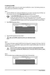
... press . • The Save Main BIOS to Drive option allows you sure to Drive Enter : Run hi:Move Total size : 0 ESC:Reset Free size : 0 F10:Power Off 3. Select the BIOS update file and press . appears, press to the main menu. Q-Flash Utility v2.15 Flash Type/Size MXIC 25L4005 512K Keep... 25L4005 512K Keep0 DfilMe(Is)DfaotuandEnable HDD 0-0 Loa d CMO S Default Enable Update BIOS from Drive Please SparevsesBaInOySketoy Dtoricvoentinue Enter : Run hi:Move ESC:Reset F10:Power Off - 51 -
... press . • The Save Main BIOS to Drive option allows you sure to Drive Enter : Run hi:Move Total size : 0 ESC:Reset Free size : 0 F10:Power Off 3. Select the BIOS update file and press . appears, press to the main menu. Q-Flash Utility v2.15 Flash Type/Size MXIC 25L4005 512K Keep... 25L4005 512K Keep0 DfilMe(Is)DfaotuandEnable HDD 0-0 Loa d CMO S Default Enable Update BIOS from Drive Please SparevsesBaInOySketoy Dtoricvoentinue Enter : Run hi:Move ESC:Reset F10:Power Off - 51 -

Manual
Page 52
...(M.I.T.) Load Fail-Safe Defaults Standard CMOS Features Load Optimized Defaults Advanced BIOS Features Set Supervisor Password Integrated Peripherals Set User Password Power Management Setup PnP/PCI Configurations Save & Exit Setup Load Optimized Defa ul ts (Y/NE)?xiYt Without Saving PC Health Status ESC: Quit F8...
...(M.I.T.) Load Fail-Safe Defaults Standard CMOS Features Load Optimized Defaults Advanced BIOS Features Set Supervisor Password Integrated Peripherals Set User Password Power Management Setup PnP/PCI Configurations Save & Exit Setup Load Optimized Defa ul ts (Y/NE)?xiYt Without Saving PC Health Status ESC: Quit F8...


