User Manual
Page 2
Motherboard GA-A75-UD4H Jun. 10, 2011 Motherboard GA-A75-UD4H Jun. 10, 2011
Motherboard GA-A75-UD4H Jun. 10, 2011 Motherboard GA-A75-UD4H Jun. 10, 2011

User Manual
Page 3
...notice. Example: For product-related information, check on our website at: http://www.gigabyte.com Identifying Your Motherboard Revision The revision number on your motherboard revision before updating motherboard BIOS, drivers, or when looking for technical information. The trademarks mentioned in the...copied, translated, transmitted, or published in this : "REV: X.X." No part of GIGABYTE. For example, "REV: 1.0" means the revision of the motherboard is the property of this product, GIGABYTE provides the following types of documentations: For quick set-up of the ...
...notice. Example: For product-related information, check on our website at: http://www.gigabyte.com Identifying Your Motherboard Revision The revision number on your motherboard revision before updating motherboard BIOS, drivers, or when looking for technical information. The trademarks mentioned in the...copied, translated, transmitted, or published in this : "REV: X.X." No part of GIGABYTE. For example, "REV: 1.0" means the revision of the motherboard is the property of this product, GIGABYTE provides the following types of documentations: For quick set-up of the ...
User Manual
Page 4
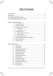
Table of Contents Box Contents...6 Optional Items...6 GA-A75-UD4H Motherboard Layout 7 GA-A75-UD4H Motherboard Block Diagram 8 Chapter 1 Hardware Installation 9 1-1 Installation Precautions 9 1-2 Product Specifications 10 1-3 Installing the APU and APU Cooler 13 1-3-1 Installing the APU...13 1-3-2 Installing the APU Cooler ...
Table of Contents Box Contents...6 Optional Items...6 GA-A75-UD4H Motherboard Layout 7 GA-A75-UD4H Motherboard Block Diagram 8 Chapter 1 Hardware Installation 9 1-1 Installation Precautions 9 1-2 Product Specifications 10 1-3 Installing the APU and APU Cooler 13 1-3-1 Installing the APU...13 1-3-2 Installing the APU Cooler ...

User Manual
Page 6
Optional Items 2-port USB 2.0 bracket (Part No. 12CR1-1UB030-5*R) 2-port SATA power cable (Part No. 12CF1-2SERPW-0*R) 2-port IEEE 1394a bracket (Part No. 12CF1-1IE008-0*R) COM port cable (Part No. 12CF1-1CM001-3*R) 3.5" Front Panel with 2 USB 3.0/2.0 ports (Part No. 12CR1-FPX582-0*R) - 6 - The box contents are for reference only and the actual items shall depend on the product package you obtain. Box Contents GA-A75-UD4H motherboard Motherboard driver disk User's Manual Quick Installation Guide Four SATA cables I/O Shield The box contents above are subject to change without notice.
Optional Items 2-port USB 2.0 bracket (Part No. 12CR1-1UB030-5*R) 2-port SATA power cable (Part No. 12CF1-2SERPW-0*R) 2-port IEEE 1394a bracket (Part No. 12CF1-1IE008-0*R) COM port cable (Part No. 12CF1-1CM001-3*R) 3.5" Front Panel with 2 USB 3.0/2.0 ports (Part No. 12CR1-FPX582-0*R) - 6 - The box contents are for reference only and the actual items shall depend on the product package you obtain. Box Contents GA-A75-UD4H motherboard Motherboard driver disk User's Manual Quick Installation Guide Four SATA cables I/O Shield The box contents above are subject to change without notice.

User Manual
Page 7
GA-A75-UD4H Motherboard Layout KB_MS_USB3 SYS_FAN2 CPU_FAN VGA_DVI ATX_12V Socket FM1 Etron EJ168 ATX DP_HDMI_SPDIF PWR_FAN ESATA_1394_USB USB30_LAN AUDIO Realtek RTL8111E Etron EJ168 PCIEX1_1 PCIEX16 GA-A75-UD4H COM TPM DDR3_4 DDR3_2 DDR3_3 iTE DDR3_1 IT8720 SATA3_4 CODEC PCIEX1_2 PCIEX1_3 PCIEX8 PCI1 BAT B_BIOS M_BIOS SYS_FAN AMD A75 SATA3_3 SATA3_2 SATA3_1 SATA3_0 VIA VT6308 PCI2 F_AUDIO CLR_CMOS F_PANEL SPDIF_O F_USB4 F_USB2 F_USB30_2 F_1394 F_USB3 F_USB1 F_USB30_1 - 7 -
GA-A75-UD4H Motherboard Layout KB_MS_USB3 SYS_FAN2 CPU_FAN VGA_DVI ATX_12V Socket FM1 Etron EJ168 ATX DP_HDMI_SPDIF PWR_FAN ESATA_1394_USB USB30_LAN AUDIO Realtek RTL8111E Etron EJ168 PCIEX1_1 PCIEX16 GA-A75-UD4H COM TPM DDR3_4 DDR3_2 DDR3_3 iTE DDR3_1 IT8720 SATA3_4 CODEC PCIEX1_2 PCIEX1_3 PCIEX8 PCI1 BAT B_BIOS M_BIOS SYS_FAN AMD A75 SATA3_3 SATA3_2 SATA3_1 SATA3_0 VIA VT6308 PCI2 F_AUDIO CLR_CMOS F_PANEL SPDIF_O F_USB4 F_USB2 F_USB30_2 F_1394 F_USB3 F_USB1 F_USB30_1 - 7 -

User Manual
Page 8
GA-A75-UD4H Motherboard Block Diagram 1 PCI Express x16 APU CLK+/- (100 MHz) 2 PCI Express x8 or AMD APU DISP CLK+/- (100 MHz) DDR3 2400 (O.C.)/1866/ 1600/1333/1066 ... UMI 3 PCI Express x1 RJ45 PCIe CLK (100 MHz) Realtek RTL8111E x1 x1 x1 x1 PCI Express Bus x1 Etron EJ168 x1 Etron EJ168 AMD A75 D-Sub 4 USB 3.0/2.0 10 USB 2.0/1.1 Dual BIOS 2 USB 3.0/2.0 2 USB 3.0/2.0 PCI Bus 6 SATA 6Gb/s VIA VT6308 2 IEEE 1394a CODEC LPC Bus iTE IT8720 COM Port PS/2 KB...
GA-A75-UD4H Motherboard Block Diagram 1 PCI Express x16 APU CLK+/- (100 MHz) 2 PCI Express x8 or AMD APU DISP CLK+/- (100 MHz) DDR3 2400 (O.C.)/1866/ 1600/1333/1066 ... UMI 3 PCI Express x1 RJ45 PCIe CLK (100 MHz) Realtek RTL8111E x1 x1 x1 x1 PCI Express Bus x1 Etron EJ168 x1 Etron EJ168 AMD A75 D-Sub 4 USB 3.0/2.0 10 USB 2.0/1.1 Dual BIOS 2 USB 3.0/2.0 2 USB 3.0/2.0 PCI Bus 6 SATA 6Gb/s VIA VT6308 2 IEEE 1394a CODEC LPC Bus iTE IT8720 COM Port PS/2 KB...

User Manual
Page 9
...and power connectors of your hands dry and first touch a metal object to eliminate static electricity. • Prior to installing the motherboard, please have it on top of an antistatic pad or within an electrostatic shielding container. • Before unplugging the power supply... cable from the power outlet before installing or removing the motherboard or other hardware components. • When connecting hardware components to the internal connectors on the computer power during the installation process...
...and power connectors of your hands dry and first touch a metal object to eliminate static electricity. • Prior to installing the motherboard, please have it on top of an antistatic pad or within an electrostatic shielding container. • Before unplugging the power supply... cable from the power outlet before installing or removing the motherboard or other hardware components. • When connecting hardware components to the internal connectors on the computer power during the installation process...

User Manual
Page 12
... Center ŠŠ Support for Xpress Install ŠŠ Support for Xpress Recovery2 ŠŠ Support for EasyTune * Available functions in EasyTune may differ by motherboard model. ŠŠ Support for Smart Recovery ŠŠ Support for Auto Green ŠŠ Support for ON/OFF Charge ŠŠ Support for 3TB...
... Center ŠŠ Support for Xpress Install ŠŠ Support for Xpress Recovery2 ŠŠ Support for EasyTune * Available functions in EasyTune may differ by motherboard model. ŠŠ Support for Smart Recovery ŠŠ Support for Auto Green ŠŠ Support for ON/OFF Charge ŠŠ Support for 3TB...

User Manual
Page 13
... turn off the computer and unplug the power cord from the power outlet before you wish to GIGABYTE's website for the peripherals. If you begin to install the APU: • Make sure that the motherboard supports the APU. (Go to set beyond the standard specifications, please do so according to your hardware...
... turn off the computer and unplug the power cord from the power outlet before you wish to GIGABYTE's website for the peripherals. If you begin to install the APU: • Make sure that the motherboard supports the APU. (Go to set beyond the standard specifications, please do so according to your hardware...

User Manual
Page 14
... position. APU Socket Locking Lever Step 1: Completely lift up the APU socket locking lever. Follow the steps below to correctly install the APU into the motherboard APU socket. • Before installing the APU, make sure to turn off the computer and unplug the power cord from the power outlet to prevent...
... position. APU Socket Locking Lever Step 1: Completely lift up the APU socket locking lever. Follow the steps below to correctly install the APU into the motherboard APU socket. • Before installing the APU, make sure to turn off the computer and unplug the power cord from the power outlet to prevent...

User Manual
Page 15
.... Step 3: Hook the APU cooler clip to the mounting lug on one side of the APU cooler to the APU fan header (CPU_FAN) on the motherboard. Step 4: Turn the cam handle from the left side to the right side (as the example.) Step 1: Apply an even and thin layer of thermal... to the APU. 1-3-2 Installing the APU Cooler Follow the steps below to correctly install the APU cooler on the APU. (The following procedure uses the GIGABYTE cooler as the picture above shows) to lock into place. (Refer to your APU cooler installation manual for instructions on installing the cooler.) Step 5: Finally...
.... Step 3: Hook the APU cooler clip to the mounting lug on one side of the APU cooler to the APU fan header (CPU_FAN) on the motherboard. Step 4: Turn the cam handle from the left side to the right side (as the example.) Step 1: Apply an even and thin layer of thermal... to the APU. 1-3-2 Installing the APU Cooler Follow the steps below to correctly install the APU cooler on the APU. (The following procedure uses the GIGABYTE cooler as the picture above shows) to lock into place. (Refer to your APU cooler installation manual for instructions on installing the cooler.) Step 5: Finally...

User Manual
Page 16
...Channel mode with two memory modules, we recommend that memory of the same capacity, brand, speed, and chips be used . (Go to GIGABYTE's website for the latest supported memory speeds and memory modules.) • Always turn off the computer and unplug the power cord from the ...capacity of the memory. The four DDR3 memory sockets are unable to insert the memory, switch the direction. 1-4-1 Dual Channel Memory Configuration This motherboard provides four DDR3 memory sockets and supports Dual Channel Technology. DS/SS (SS=Single-Sided, DS=Double-Sided, "- -"=No Memory) DDR3_4 DDR3_2...
...Channel mode with two memory modules, we recommend that memory of the same capacity, brand, speed, and chips be used . (Go to GIGABYTE's website for the latest supported memory speeds and memory modules.) • Always turn off the computer and unplug the power cord from the ...capacity of the memory. The four DDR3 memory sockets are unable to insert the memory, switch the direction. 1-4-1 Dual Channel Memory Configuration This motherboard provides four DDR3 memory sockets and supports Dual Channel Technology. DS/SS (SS=Single-Sided, DS=Double-Sided, "- -"=No Memory) DDR3_4 DDR3_2...

User Manual
Page 17
... the memory socket. DDR3 and DDR2 DIMMs are not compatible to each other or DDR DIMMs. Be sure to correctly install your fingers on this motherboard. Follow the steps below to install DDR3 DIMMs on the top edge of the memory module. Place the memory module on the memory and insert...
... the memory socket. DDR3 and DDR2 DIMMs are not compatible to each other or DDR DIMMs. Be sure to correctly install your fingers on this motherboard. Follow the steps below to install DDR3 DIMMs on the top edge of the memory module. Place the memory module on the memory and insert...

User Manual
Page 18
... the slot. 3. Remove the metal slot cover from the slot. If necessary, go to BIOS Setup to install an expansion card: • Make sure the motherboard supports the expansion card. Hardware Installation - 18 - • Removing the Card from the PCIEX8 Slot: Press the latch at the end of the card until...
... the slot. 3. Remove the metal slot cover from the slot. If necessary, go to BIOS Setup to install an expansion card: • Make sure the motherboard supports the expansion card. Hardware Installation - 18 - • Removing the Card from the PCIEX8 Slot: Press the latch at the end of the card until...
User Manual
Page 19
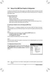
... Graphics technology can provide significantly advanced display performance for more details, please visit AMD's official website) and correct driver B. An AMD Dual Graphics technology-supported motherboard and correct driver - Save the settings and exit BIOS Setup. Installing the Graphics Cards and Configuring BIOS Setup Step 1: Observe the steps in the operating...
... Graphics technology can provide significantly advanced display performance for more details, please visit AMD's official website) and correct driver B. An AMD Dual Graphics technology-supported motherboard and correct driver - Save the settings and exit BIOS Setup. Installing the Graphics Cards and Configuring BIOS Setup Step 1: Observe the steps in the operating...

User Manual
Page 21
... is enabled. DisplayPort (Note) DisplayPort is one of 2560x1600, but the actual resolutions supported are dependent on the monitor being used . Dual Display Configurations: This motherboard provides four video output ports: D-Sub, DVI-D, HDMI, and DisplayPort. Playback of UMA Frame Buffer Size (refer to the recommended system requirements (or better) below...
... is enabled. DisplayPort (Note) DisplayPort is one of 2560x1600, but the actual resolutions supported are dependent on the monitor being used . Dual Display Configurations: This motherboard provides four video output ports: D-Sub, DVI-D, HDMI, and DisplayPort. Playback of UMA Frame Buffer Size (refer to the recommended system requirements (or better) below...
User Manual
Page 22
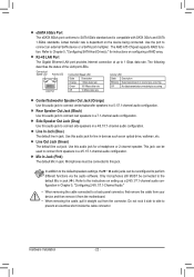
... functions via the audio software. Use the port to prevent an electrical short inside the cable connector. Do not rock it straight out from the motherboard. • When removing the cable, pull it side to side to connect an external SATA device or a SATA port multiplier. Refer to 1 Gbps data ...first remove the cable from your device and then remove it from the connector. Line Out Jack (Green) The default line out jack. The AMD A75 Chipset supports RAID function. Mic In Jack (Pink) The default Mic in jack. Refer to the instructions on the device being connected. Rear Speaker Out...
... functions via the audio software. Use the port to prevent an electrical short inside the cable connector. Do not rock it straight out from the motherboard. • When removing the cable, pull it side to side to connect an external SATA device or a SATA port multiplier. Refer to 1 Gbps data ...first remove the cable from your device and then remove it from the connector. Line Out Jack (Green) The default line out jack. The AMD A75 Chipset supports RAID function. Mic In Jack (Pink) The default Mic in jack. Refer to the instructions on the device being connected. Rear Speaker Out...

User Manual
Page 23
...) SPDIF_O 11) F_USB1/F_USB2/F_USB3/F_USB4 12) F_USB30_1/F_USB30_2 13) F_1394 14) COM 15) TPM 16) CLR_CMOS Read the following guidelines before turning on the motherboard. - 23 - Unplug the power cord from the power outlet to prevent damage to the devices. • After installing the device and before connecting external devices...
...) SPDIF_O 11) F_USB1/F_USB2/F_USB3/F_USB4 12) F_USB30_1/F_USB30_2 13) F_1394 14) COM 15) TPM 16) CLR_CMOS Read the following guidelines before turning on the motherboard. - 23 - Unplug the power cord from the power outlet to prevent damage to the devices. • After installing the device and before connecting external devices...

User Manual
Page 24
... mainly supplies power to the power connector in the correct orientation. If the 12V power connector is turned off and all the components on the motherboard. 1/2) ATX_12V/ATX (2x4 12V Power Connector and 2x12 Main Power Connector) With the use of the power connector, the power supply can supply enough stable...
... mainly supplies power to the power connector in the correct orientation. If the 12V power connector is turned off and all the components on the motherboard. 1/2) ATX_12V/ATX (2x4 12V Power Connector and 2x12 Main Power Connector) With the use of the power connector, the power supply can supply enough stable...

User Manual
Page 25
...Be sure to connect fan cables to the fan headers to replace the battery by removing the battery: 1. 3/4/5) CPU_FAN/SYS_FAN/SYS_FAN2/PWR_FAN (Fan Headers) The motherboard has a 4-pin CPU fan header (CPU_FAN), a 4-pin (SYS_FAN) and a 3-pin (SYS_FAN2) system fan headers, and a 3-pin power fan header .../Speed Control 3 Sense 4 Reserve SYS_FAN2/PWR_FAN: 1 SYS_FAN2 PWR_FAN Pin No. Danger of the battery holder, making them short for one . The motherboard supports APU fan speed control, which requires the use of a APU fan with an equivalent one minute. (Or use a metal object like a ...
...Be sure to connect fan cables to the fan headers to replace the battery by removing the battery: 1. 3/4/5) CPU_FAN/SYS_FAN/SYS_FAN2/PWR_FAN (Fan Headers) The motherboard has a 4-pin CPU fan header (CPU_FAN), a 4-pin (SYS_FAN) and a 3-pin (SYS_FAN2) system fan headers, and a 3-pin power fan header .../Speed Control 3 Sense 4 Reserve SYS_FAN2/PWR_FAN: 1 SYS_FAN2 PWR_FAN Pin No. Danger of the battery holder, making them short for one . The motherboard supports APU fan speed control, which requires the use of a APU fan with an equivalent one minute. (Or use a metal object like a ...


