User Manual
Page 2
... 5 GA-9IVDTH Motherboard Layout 7 Chapter 2 Hardware Installation Process 9 Step 1: Install the Central Processing Unit (CPU 10 Step 1-2:CPU Heat Sink Installation 11 Step 2: Install memory modules 13 2-1: DDR DIMM Slot Population 14 Step 3: Install expansion cards 16 Step 4: Connect ribbon cables, cabinet wires, and power supply 17 Step 4-1 : I/O Back Panel Introduction 17 Step 4-2 :Connectors Introduction 19 Step 4-3 : Jumper Setting Introduction 28 Chapter 3 BIOS Setup 34 Main ...36 Advanced 39 PCI Configuration ...40 Advanced Chipset Control 42 Advanced Processor Option 45...
... 5 GA-9IVDTH Motherboard Layout 7 Chapter 2 Hardware Installation Process 9 Step 1: Install the Central Processing Unit (CPU 10 Step 1-2:CPU Heat Sink Installation 11 Step 2: Install memory modules 13 2-1: DDR DIMM Slot Population 14 Step 3: Install expansion cards 16 Step 4: Connect ribbon cables, cabinet wires, and power supply 17 Step 4-1 : I/O Back Panel Introduction 17 Step 4-2 :Connectors Introduction 19 Step 4-3 : Jumper Setting Introduction 28 Chapter 3 BIOS Setup 34 Main ...36 Advanced 39 PCI Configuration ...40 Advanced Chipset Control 42 Advanced Processor Option 45...
User Manual
Page 4
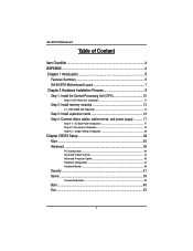
.... English GA-9IVDTH Motherboard Item Checklist The GA-9IVDTH motherboard U320 SCSI cable x 1 USB 2.0 cable x 1 CD for motherboard driver & utility GA-9IVDTH user's manual Serial ATA cable x 2 PATA cable x 1 & FDD cable set x 1 CPU retention module x 1 I/O Shield x1 COM2 cable x 1 WARNING! If the motherboard has mounting holes, but they don't line up with the components whenever the components are separated from static electricity, you should follow some precautions whenever you plug in or remove the ATX power connector on your...
.... English GA-9IVDTH Motherboard Item Checklist The GA-9IVDTH motherboard U320 SCSI cable x 1 USB 2.0 cable x 1 CD for motherboard driver & utility GA-9IVDTH user's manual Serial ATA cable x 2 PATA cable x 1 & FDD cable set x 1 CPU retention module x 1 I/O Shield x1 COM2 cable x 1 WARNING! If the motherboard has mounting holes, but they don't line up with the components whenever the components are separated from static electricity, you should follow some precautions whenever you plug in or remove the ATX power connector on your...

User Manual
Page 5
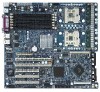
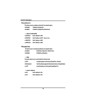
...EPP/ECP mode y 2 Serial port (1 at rear, 1 by cable) y 4 x USB 2.0 (2 X at rear, 2 x by 8 x 1 y 3 PCI slot supports 32/33MHz (5V) y 1 IDE bus master (ATA100) IDE ports for up to 24GB DRAM (Max) for DDR-333 (Optional) y Supports up to 12 GB DRAM (Max) for DDR-266 y Supports only 2.5V DDR DIMM y IT8712 F IX y 2 PCI-X slot support 64/66MHz y 1 PCI-E slot by cable) y 1 x VGA port y 2 x RJ45 LAN port y CPU/Power/System Fan Revolution Detect y CPU shutdown when overheat y System Voltage Detect 5 y GA-9IVDTH Motherboard: CPU Chipset Memory I/O Control Slots On-Board IDE y Dual socket 604 for...
...EPP/ECP mode y 2 Serial port (1 at rear, 1 by cable) y 4 x USB 2.0 (2 X at rear, 2 x by 8 x 1 y 3 PCI slot supports 32/33MHz (5V) y 1 IDE bus master (ATA100) IDE ports for up to 24GB DRAM (Max) for DDR-333 (Optional) y Supports up to 12 GB DRAM (Max) for DDR-266 y Supports only 2.5V DDR DIMM y IT8712 F IX y 2 PCI-X slot support 64/66MHz y 1 PCI-E slot by cable) y 1 x VGA port y 2 x RJ45 LAN port y CPU/Power/System Fan Revolution Detect y CPU shutdown when overheat y System Voltage Detect 5 y GA-9IVDTH Motherboard: CPU Chipset Memory I/O Control Slots On-Board IDE y Dual socket 604 for...
User Manual
Page 6
... GA-9IVDTH Motherboard SCSI Controller On-Board SATA RAID y Adaptec® 7902W chipset supports dual ultra 320 SCSI channels y Mirroring supports automatic background rebuilds y Supports RAID 0 ,1, 10 y Supports HOST RAID y Features LBA and Extended Interrupt 13 drive translation in controller onboard BIOS y Intel® 6300ESB chipset supports SATA and HOST RAID 0,1 On-Board LAN PS/2 Connector BIOS Additional Features y Build in dual Intel® 82541 LAN Chipset y PS/2 Keyboard interface and PS/2 Mouse interace y Lincensed Pheonix on 8Mb Flash RAM y Supports multi boot function y User...
... GA-9IVDTH Motherboard SCSI Controller On-Board SATA RAID y Adaptec® 7902W chipset supports dual ultra 320 SCSI channels y Mirroring supports automatic background rebuilds y Supports RAID 0 ,1, 10 y Supports HOST RAID y Features LBA and Extended Interrupt 13 drive translation in controller onboard BIOS y Intel® 6300ESB chipset supports SATA and HOST RAID 0,1 On-Board LAN PS/2 Connector BIOS Additional Features y Build in dual Intel® 82541 LAN Chipset y PS/2 Keyboard interface and PS/2 Mouse interace y Lincensed Pheonix on 8Mb Flash RAM y Supports multi boot function y User...
User Manual
Page 9
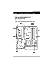
Hardware Installation Process Chapter 2 Hardware Installation Process To set up your computer, you must complete the following steps: Step 1- Install expansion cards Step 4- Connect ribbon cables, cabinet wires, and power supply Step3 Step 2 Step4 㕳㕨 㖃㖀㕻㕡 㕴㕥㕠 㖃㖇㕡...13668;㕩 㕥㕠 㕹㕦 Step4 㕺㖀㕧 㖅㕥㕥 Step1 9 Install the Central Processing Unit (CPU) Step 2- Install memory modules Step 3-
Hardware Installation Process Chapter 2 Hardware Installation Process To set up your computer, you must complete the following steps: Step 1- Install expansion cards Step 4- Connect ribbon cables, cabinet wires, and power supply Step3 Step 2 Step4 㕳㕨 㖃㖀㕻㕡 㕴㕥㕠 㖃㖇㕡...13668;㕩 㕥㕠 㕹㕦 Step4 㕺㖀㕧 㖅㕥㕥 Step1 9 Install the Central Processing Unit (CPU) Step 2- Install memory modules Step 3-

User Manual
Page 10
... not match the CPU socket Pin 1 and CPU cut edge on the CPU upper corner. CPU Top View Pin1 indicator 3. Locate Pin 1 in the socket and look for a (golden) cut edge well, it will cause improper installation. Please change the insert orientation. Pin1 indicator 2. Please make sure the CPU type is supported by the motherboard. 1. English GA-9IVDTH Motherboard Step 1: Install the Central Processing Unit (CPU) Before installing the processor , adhere to...
... not match the CPU socket Pin 1 and CPU cut edge on the CPU upper corner. CPU Top View Pin1 indicator 3. Locate Pin 1 in the socket and look for a (golden) cut edge well, it will cause improper installation. Please change the insert orientation. Pin1 indicator 2. Please make sure the CPU type is supported by the motherboard. 1. English GA-9IVDTH Motherboard Step 1: Install the Central Processing Unit (CPU) Before installing the processor , adhere to...

User Manual
Page 13
... warning: Please note that the DIMM module can only fit in one notches. The BIOS will cause improper installation. Wrong orientation will automatically detects memory type and size. Step 2: Install memory modules Hardware Installation Process Before installing the processor and heatsink, adhere to the notch. Memory size can vary between sockets. 㖃㖀㕻㕡 㕴㕥㕠 㖃㖇㕡 㕡 㖃㕾...
... warning: Please note that the DIMM module can only fit in one notches. The BIOS will cause improper installation. Wrong orientation will automatically detects memory type and size. Step 2: Install memory modules Hardware Installation Process Before installing the processor and heatsink, adhere to the notch. Memory size can vary between sockets. 㖃㖀㕻㕡 㕴㕥㕠 㖃㖇㕡 㕡 㖃㕾...

User Manual
Page 37
... [Auto] to set all HDD parameters automatically. Auto type which will be provided in the computer. TYPE 1-39: Predefined types. Manual type is installed here. 37 BIOS Setup Legacy Diskette A This category identifies the type of floppy disk drive A that the specifications of hard disk from drive C to the following items. Enter the information directly from the keyboard and press . Auto: Set parameters automatically. (Default Vaules) CD-ROM: Use for this device. 360KB, 51/4 in. 31/2 inch AT-type high-density drive...
... [Auto] to set all HDD parameters automatically. Auto type which will be provided in the computer. TYPE 1-39: Predefined types. Manual type is installed here. 37 BIOS Setup Legacy Diskette A This category identifies the type of floppy disk drive A that the specifications of hard disk from drive C to the following items. Enter the information directly from the keyboard and press . Auto: Set parameters automatically. (Default Vaules) CD-ROM: Use for this device. 360KB, 51/4 in. 31/2 inch AT-type high-density drive...

User Manual
Page 40
GA-9IVDTH Motherboard PCI Configuration PhoenixBIOS Setup Utility PCI Configuration Embedded Vedio Controller Embedded SCSI RAID Controller Embedded NIC Item Specific Help F1: Help Esc: Exit KL: Select Item IJ: Select Menu + -: Change Values F5: Setup Defaults Enter: Select Sub-Menu F10: Save&Exit Figure 2-1: PCI Configuration Embedded Video Controller Onboard VGA Control Enabled Enable onboard VGA device. (Default value) Disabled Disable this function. (Defualt value) 40 Disabled Disable this function. Embedded SCSI RAID Controller Option ROM Scan Enabled Enableing ...
GA-9IVDTH Motherboard PCI Configuration PhoenixBIOS Setup Utility PCI Configuration Embedded Vedio Controller Embedded SCSI RAID Controller Embedded NIC Item Specific Help F1: Help Esc: Exit KL: Select Item IJ: Select Menu + -: Change Values F5: Setup Defaults Enter: Select Sub-Menu F10: Save&Exit Figure 2-1: PCI Configuration Embedded Video Controller Onboard VGA Control Enabled Enable onboard VGA device. (Default value) Disabled Disable this function. (Defualt value) 40 Disabled Disable this function. Embedded SCSI RAID Controller Option ROM Scan Enabled Enableing ...

User Manual
Page 42
Legacy USB Support This option allows user to the desired value. Disabled Disables support for legacy USB. GA-9IVDTH Motherboard Advanced Chipset Control PhoenixBIOS Setup Utility Advanced Chipset Control USB Controller [Enabled] Legacy USB Support [Disabled] Force Compliance Mode [Enabled] PCI-E port A Device 2 [Enabled] 4GB PCI Hole Granularity [128MB] Data Parity Error Recovery [Enabled] Wake On LAN [Enabled] Item Specific Help F1: Help Esc: Exit KL: Select Item IJ: Select Menu + -: Change Values F5: Setup Defaults Enter: Select Sub-Menu F10: Save&Exit ...
Legacy USB Support This option allows user to the desired value. Disabled Disables support for legacy USB. GA-9IVDTH Motherboard Advanced Chipset Control PhoenixBIOS Setup Utility Advanced Chipset Control USB Controller [Enabled] Legacy USB Support [Disabled] Force Compliance Mode [Enabled] PCI-E port A Device 2 [Enabled] 4GB PCI Hole Granularity [128MB] Data Parity Error Recovery [Enabled] Wake On LAN [Enabled] Item Specific Help F1: Help Esc: Exit KL: Select Item IJ: Select Menu + -: Change Values F5: Setup Defaults Enter: Select Sub-Menu F10: Save&Exit ...

User Manual
Page 47
Enabled Enable the configuration (Default value) Base I /O addreee [378] Floppy disk connector [Disabled] Floppy Check [Enabled] Parallel ATA [Both] Serial ATA [Enabled] Native Mode Operation [Auto] SATA RAID Enable [Disabled] F1: Help Esc: Exit KL: Select Item IJ: Select Menu + -: Change Values F5: Setup Defaults Enter: Select Sub-Menu F10: Save&Exit Figure 2-4: Peripheral Configuration Serial Port A This allows users to 2E8. 47 BIOS Setup Peripheral Configuration PhoenixBIOS Setup Utility Peripheral Configuration Item Specific Help Serial Port A [Enabled] ...
Enabled Enable the configuration (Default value) Base I /O addreee [378] Floppy disk connector [Disabled] Floppy Check [Enabled] Parallel ATA [Both] Serial ATA [Enabled] Native Mode Operation [Auto] SATA RAID Enable [Disabled] F1: Help Esc: Exit KL: Select Item IJ: Select Menu + -: Change Values F5: Setup Defaults Enter: Select Sub-Menu F10: Save&Exit Figure 2-4: Peripheral Configuration Serial Port A This allows users to 2E8. 47 BIOS Setup Peripheral Configuration PhoenixBIOS Setup Utility Peripheral Configuration Item Specific Help Serial Port A [Enabled] ...
User Manual
Page 48
Mode This option allows user to 278. 48 EPP Using Parallel port as Extended Capabilities Port. Enabled Enable the configuration. (Default value) Disabled Disable the configuration. GA-9IVDTH Motherboard Serial Port B This allows users to configure serial prot B by using this option. Parallel Port This allows users to configure parallel port by using this setting to 2E8. ECP Using Parallel port as Enhanced Parallel Port. (Default) Bi-directional Use this option. Base I /O Address/IRQ 3F8/IRQ4 Set IO address to 3F8. 2F8/IRQ3 Set IO address to 2F8...
Mode This option allows user to 278. 48 EPP Using Parallel port as Extended Capabilities Port. Enabled Enable the configuration. (Default value) Disabled Disable the configuration. GA-9IVDTH Motherboard Serial Port B This allows users to configure serial prot B by using this option. Parallel Port This allows users to configure parallel port by using this setting to 2E8. ECP Using Parallel port as Enhanced Parallel Port. (Default) Bi-directional Use this option. Base I /O Address/IRQ 3F8/IRQ4 Set IO address to 3F8. 2F8/IRQ3 Set IO address to 2F8...

User Manual
Page 49
...) BIOS Setup Floppy Check Enabled Disabled Enable the device to set the native mode for ATA function. Native Mode Operation This option allows user to verify floppy typer when system boot. (Default value) Disable the this function. Note that certain OS is not supported under Native Mode. Parallel ATA Set Native mode to Serial ATA. SATA RAID Enable Enabled Disabled Enable the SATA RAID function. Select both Channel 0 as Parallel ATA. Auto Auto detected. (Default value) Serial ATA Set Native mode to Parallel ATA. Floppy disk controller Enabled Enable the floppy...
...) BIOS Setup Floppy Check Enabled Disabled Enable the device to set the native mode for ATA function. Native Mode Operation This option allows user to verify floppy typer when system boot. (Default value) Disable the this function. Note that certain OS is not supported under Native Mode. Parallel ATA Set Native mode to Serial ATA. SATA RAID Enable Enabled Disabled Enable the SATA RAID function. Select both Channel 0 as Parallel ATA. Auto Auto detected. (Default value) Serial ATA Set Native mode to Parallel ATA. Floppy disk controller Enabled Enable the floppy...

User Manual
Page 51
... and not enter a specified password or press key to 6 characters in lengh and press . You will clear any previously entered password from the CMOS memory. Type the password again and press . Security Main Advanced Supervisor Password Is: Supervisor Password Is: Set Supervisor Password Set User Password Password On Boot PhoenixBIOS Setup Utility Security Server Boot Clear Clear [Enter] [Enter] [Disabled] BIOS Setup Exit Item Specific Help F1: Help Esc: Exit KL: Select Item IJ: Select Menu + -: Change Values F5: Setup Defaults Enter: Select Sub-Menu F10: Save...
... and not enter a specified password or press key to 6 characters in lengh and press . You will clear any previously entered password from the CMOS memory. Type the password again and press . Security Main Advanced Supervisor Password Is: Supervisor Password Is: Set Supervisor Password Set User Password Password On Boot PhoenixBIOS Setup Utility Security Server Boot Clear Clear [Enter] [Enter] [Disabled] BIOS Setup Exit Item Specific Help F1: Help Esc: Exit KL: Select Item IJ: Select Menu + -: Change Values F5: Setup Defaults Enter: Select Sub-Menu F10: Save...
User Manual
Page 56
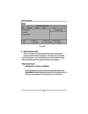
GA-9IVDTH Motherboard Boot Main Advanced + CD-ROM Drive + Hard Drive Removable Device PhoenixBIOS Setup Utility Security Server Boot Exit Item Specific Help F1: Help Esc: Exit KL: Select Item IJ: Select Menu + -: Change Values F5: Setup Defaults Enter: Select Sub-Menu F10: Save&Exit Figure 5: Boot * About This Section: Boot The "Boot" menu allows user to select among four possible types of device the system attempt to search for next available device. 56 By applying and key, you can promote...
GA-9IVDTH Motherboard Boot Main Advanced + CD-ROM Drive + Hard Drive Removable Device PhoenixBIOS Setup Utility Security Server Boot Exit Item Specific Help F1: Help Esc: Exit KL: Select Item IJ: Select Menu + -: Change Values F5: Setup Defaults Enter: Select Sub-Menu F10: Save&Exit Figure 5: Boot * About This Section: Boot The "Boot" menu allows user to select among four possible types of device the system attempt to search for next available device. 56 By applying and key, you can promote...
User Manual
Page 61
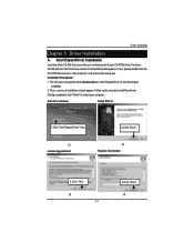
... auto start the chipset installation. 2. Installation Procedures: 1. Then, a series of Setup Wizard dialog boxes. Follow up the wizards to install the drivers. 3.Setup completed, click "Finish" to start and show a series of installation wizards appear. Intel Chipset Driver Installation Insert the driver CD-title that came with your motherboard into your computer. If not, please double click the CD-ROM device icon in "My computer", and execute the setup.exe. Auto Run windows Setup...
... auto start the chipset installation. 2. Installation Procedures: 1. Then, a series of Setup Wizard dialog boxes. Follow up the wizards to install the drivers. 3.Setup completed, click "Finish" to start and show a series of installation wizards appear. Intel Chipset Driver Installation Insert the driver CD-title that came with your motherboard into your computer. If not, please double click the CD-ROM device icon in "My computer", and execute the setup.exe. Auto Run windows Setup...
User Manual
Page 63
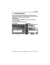
...-ROM device icon in "My computer", and execute the setup.exe. Driver Installation B. Intel LAN Driver Installation Insert the driver CD-title that came with your motherboard into your CD-ROM driver, the driver CD-title will auto start the installation. 2. Select "Install Base Driver. 3. Installation Procedures: 1. The CD auto run program starts, Double click on "Intel LAN Driver" to install the LAN Driver automatically. System stasts to start and show a series of Setup Wizard dialog boxes. Auto Run windows Install Base Driver...
...-ROM device icon in "My computer", and execute the setup.exe. Driver Installation B. Intel LAN Driver Installation Insert the driver CD-title that came with your motherboard into your CD-ROM driver, the driver CD-title will auto start the installation. 2. Select "Install Base Driver. 3. Installation Procedures: 1. The CD auto run program starts, Double click on "Intel LAN Driver" to install the LAN Driver automatically. System stasts to start and show a series of Setup Wizard dialog boxes. Auto Run windows Install Base Driver...

User Manual
Page 64
... CD-ROM device icon in the license agreement and click "Next". (4) Select "Install Software". 3. The CD auto run program starts, Double click on "Intel LAN Driver" to restart your CD-ROM driver, the driver CD-title will auto start and show the installation guide. Then, a series of installation wizards appear. Installation Procedures: 1. GA-9IVDTH Motherboard C. Follow up the wizards to install the drivers. 4.Setup completed, click "Finish" to enter Intel Pro Network Connections Installation program. 2. Intel Pro Software Utility Installation Insert the driver CD...
... CD-ROM device icon in the license agreement and click "Next". (4) Select "Install Software". 3. The CD auto run program starts, Double click on "Intel LAN Driver" to restart your CD-ROM driver, the driver CD-title will auto start and show the installation guide. Then, a series of installation wizards appear. Installation Procedures: 1. GA-9IVDTH Motherboard C. Follow up the wizards to install the drivers. 4.Setup completed, click "Finish" to enter Intel Pro Network Connections Installation program. 2. Intel Pro Software Utility Installation Insert the driver CD...

User Manual
Page 69
... up the wizards to install the drivers. 3.Setup completed, click "Finish" to restart your CD-ROM driver, the driver CD-title will auto start the installation. 2. Click "Next" to start the installation . (3) 69 4.Click "Finish" to start and show the installation guide. Then, a series of installation wizards appear. The CD auto run program starts, Double click on "Directx9.0C" to complete the installation. (4) Installation Procedures: 1. Auto Run windows License Agreement 1.Click "DirectX...
... up the wizards to install the drivers. 3.Setup completed, click "Finish" to restart your CD-ROM driver, the driver CD-title will auto start the installation. 2. Click "Next" to start the installation . (3) 69 4.Click "Finish" to start and show the installation guide. Then, a series of installation wizards appear. The CD auto run program starts, Double click on "Directx9.0C" to complete the installation. (4) Installation Procedures: 1. Auto Run windows License Agreement 1.Click "DirectX...

User Manual
Page 70
GA-9IVDTH Motherboard RCehvaispitoenr H6istAoprypendix Acronyms Acronyms Meaning ACPI Advanced Configuration and Power Interface APM Advanced Power Management AGP Accelerated Graphics Port AMR Audio Modem Riser ACR Advanced Communications Riser BBS BIOS Boot Specification BIOS Basic Input / Output System CPU Central Processing Unit CMOS Complementary Metal Oxide Semiconductor CRIMM Continuity RIMM CNR Communication and Networking Riser DMA Direct Memory Access DMI Desktop Management Interface DIMM Dual Inline Memory Module DRM Dual Retention Mechanism DRAM ...
GA-9IVDTH Motherboard RCehvaispitoenr H6istAoprypendix Acronyms Acronyms Meaning ACPI Advanced Configuration and Power Interface APM Advanced Power Management AGP Accelerated Graphics Port AMR Audio Modem Riser ACR Advanced Communications Riser BBS BIOS Boot Specification BIOS Basic Input / Output System CPU Central Processing Unit CMOS Complementary Metal Oxide Semiconductor CRIMM Continuity RIMM CNR Communication and Networking Riser DMA Direct Memory Access DMI Desktop Management Interface DIMM Dual Inline Memory Module DRM Dual Retention Mechanism DRAM ...


