Manual
Page 1
GA-965P-DS3P Intel® CoreTM 2 Extreme quad-core / CoreTM 2 Quad / Intel® CoreTM 2 Extreme dual-core / CoreTM 2 Duo / Intel® Pentium® Processor Extreme Edition / Intel® Pentium® D / Pentium® 4 LGA775 Processor Motherboard User's Manual Rev. 3301 12ME-965PDS3P-3301R * The WEEE marking on the product indicates this product must not be disposed...
GA-965P-DS3P Intel® CoreTM 2 Extreme quad-core / CoreTM 2 Quad / Intel® CoreTM 2 Extreme dual-core / CoreTM 2 Duo / Intel® Pentium® Processor Extreme Edition / Intel® Pentium® D / Pentium® 4 LGA775 Processor Motherboard User's Manual Rev. 3301 12ME-965PDS3P-3301R * The WEEE marking on the product indicates this product must not be disposed...
Manual
Page 2
Motherboard GA-965P-DS3P Nov. 10, 2006 Motherboard GA-965P-DS3P Nov. 10, 2006
Motherboard GA-965P-DS3P Nov. 10, 2006 Motherboard GA-965P-DS3P Nov. 10, 2006
Manual
Page 4
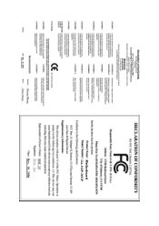
Table of Contents ItemChecklist ...6 OptionalAccessories ...6 GA-965P-DS3P Motherboard Layout 7 Block Diagram ...8 Chapter 1 Hardware Installation 9 1-1 Considerations Prior to Installation 9 1-2 Feature Summary 10 1-3 Installation of the CPU and CPU Cooler 13 1-3-1 Installation of the CPU ...
Table of Contents ItemChecklist ...6 OptionalAccessories ...6 GA-965P-DS3P Motherboard Layout 7 Block Diagram ...8 Chapter 1 Hardware Installation 9 1-1 Considerations Prior to Installation 9 1-2 Feature Summary 10 1-3 Installation of the CPU and CPU Cooler 13 1-3-1 Installation of the CPU ...
Manual
Page 7
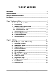
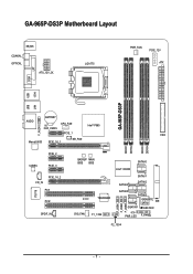
GA-965P-DS3P Motherboard Layout KB_MS COAXIAL OPTICAL ATX_12V_2X LGA775 PWR_FAN PCIE_12V ATX COM LPT 1394 USB GA-965P-DS3P LAN USB AUDIO BATTERY CPU_FAN CLR_CMOS Intel® P965 F_AUDIO PCIE_1 FDD Marvell 8053 PCIE_16_1 NB_FAN DDRII1 DDRII2 DDRII3 DDRII4 PCIE_2 CODEC PCIE_3 CD_IN PCIE_16_2 PCI1 IT8718 PCI2 SPDIF_IN BACKUP MAIN BIOS BIOS CI TSB43AB23 SYS_FAN F1_1394 SATAII0 Intel® ICH8R SATAII4 SATAII1 SATAII2 SATAII5 SATAII3 GIGABYTE SATA2 IDE GSATAII1 GSATAII0 F_USB1 F_USB2 F_USB3 PWR_LED F_PANEL F2_1394 - 7 -
GA-965P-DS3P Motherboard Layout KB_MS COAXIAL OPTICAL ATX_12V_2X LGA775 PWR_FAN PCIE_12V ATX COM LPT 1394 USB GA-965P-DS3P LAN USB AUDIO BATTERY CPU_FAN CLR_CMOS Intel® P965 F_AUDIO PCIE_1 FDD Marvell 8053 PCIE_16_1 NB_FAN DDRII1 DDRII2 DDRII3 DDRII4 PCIE_2 CODEC PCIE_3 CD_IN PCIE_16_2 PCI1 IT8718 PCI2 SPDIF_IN BACKUP MAIN BIOS BIOS CI TSB43AB23 SYS_FAN F1_1394 SATAII0 Intel® ICH8R SATAII4 SATAII1 SATAII2 SATAII5 SATAII3 GIGABYTE SATA2 IDE GSATAII1 GSATAII0 F_USB1 F_USB2 F_USB3 PWR_LED F_PANEL F2_1394 - 7 -
Manual
Page 8
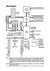
...667 MHz or 833 MHz, depending on the memory being installed. (Note 2) To use a DDR II 800/667 memory module on the motherboard, you must install a 1333/1066/ 800 MHz FSB processor. - 8 - PCI Express x1 PCI Express x3 Block Diagram PCIe CLK ... x1 x1 Switch LAN RJ45 Marvell 8056 x1 PCI Express Bus 2 SATA 3Gb/s ATA-33/66/100/ 133 IDE Channel GIGABYTE SATA2 PCI Bus LGA775 Processor CPU CLK+/-(333(Note 1)/266/200/133 MHz) Host Interface DDRII 800/667/533 MHz DIMM(...-In SPDIF In SPDIF Out PCI CLK (33 MHz) (Note 1) Applies only when the GA-965P-DS3P motherboard (rev. 3.3) is installed.
...667 MHz or 833 MHz, depending on the memory being installed. (Note 2) To use a DDR II 800/667 memory module on the motherboard, you must install a 1333/1066/ 800 MHz FSB processor. - 8 - PCI Express x1 PCI Express x3 Block Diagram PCIe CLK ... x1 x1 Switch LAN RJ45 Marvell 8056 x1 PCI Express Bus 2 SATA 3Gb/s ATA-33/66/100/ 133 IDE Channel GIGABYTE SATA2 PCI Bus LGA775 Processor CPU CLK+/-(333(Note 1)/266/200/133 MHz) Host Interface DDRII 800/667/533 MHz DIMM(...-In SPDIF In SPDIF Out PCI CLK (33 MHz) (Note 1) Applies only when the GA-965P-DS3P motherboard (rev. 3.3) is installed.
Manual
Page 9
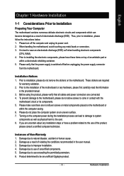
... to improper installation. 4. To prevent damage to the motherboard, please do not allow screws to the installation of Non-Warranty 1. Damage due to installation, please do not place the computer system on top of electrostatic discharge (ESD). Damage due to be an unofficial Gigabyte product. - 9 - Prior to come in the user manual...
... to improper installation. 4. To prevent damage to the motherboard, please do not allow screws to the installation of Non-Warranty 1. Damage due to installation, please do not place the computer system on top of electrostatic discharge (ESD). Damage due to be an unofficial Gigabyte product. - 9 - Prior to come in the user manual...
Manual
Page 10
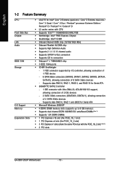
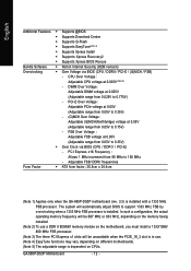
... slot) Š 3 PCI Express x1 slots (share the same PCIe bus with the PCIE_16_2 slot) (Note 3) Š 2 PCI slots GA-965P-DS3P Motherboard - 10 - Supports data RAID 0, RAID 1 and JBOD for Serial ATA Š GIGABYTE SATA2 Controller - 1 IDE connector with CPU Š Supports 1333(Note 1)/1066/800/533 MHz FSB Š Northbridge: Intel® P965...
... slot) Š 3 PCI Express x1 slots (share the same PCIe bus with the PCIE_16_2 slot) (Note 3) Š 2 PCI slots GA-965P-DS3P Motherboard - 10 - Supports data RAID 0, RAID 1 and JBOD for Serial ATA Š GIGABYTE SATA2 Controller - 1 IDE connector with CPU Š Supports 1333(Note 1)/1066/800/533 MHz FSB Š Northbridge: Intel® P965...
Manual
Page 12
... Š Supports Xpress BIOS Rescue Bundle Software Š Norton Internet Security (OEM revision) Overclocking Š Over Voltage via BIOS (CPU / DDR II / PCI-E) - GA-965P-DS3P Motherboard - 12 - The system will be unavailable when the PCIE_16_2 slot is in use. (Note 4) EasyTune functions may vary depending on CPUs. FSB Over Voltage : Adjustable... 90 MHz to 0.775V) - Adjustable FSB/ DDRII frequencies Form Factor Š ATX form factor; 30.5cm x 24.4cm (Note 1) Applies only when the GA-965P-DS3P motherboard (rev. 3.3) is installed with a 1333 MHz FSB processor.
... Š Supports Xpress BIOS Rescue Bundle Software Š Norton Internet Security (OEM revision) Overclocking Š Over Voltage via BIOS (CPU / DDR II / PCI-E) - GA-965P-DS3P Motherboard - 12 - The system will be unavailable when the PCIE_16_2 slot is in use. (Note 4) EasyTune functions may vary depending on CPUs. FSB Over Voltage : Adjustable... 90 MHz to 0.775V) - Adjustable FSB/ DDRII frequencies Form Factor Š ATX form factor; 30.5cm x 24.4cm (Note 1) Applies only when the GA-965P-DS3P motherboard (rev. 3.3) is installed with a 1333 MHz FSB processor.
Manual
Page 13
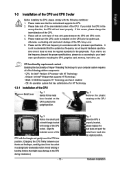
... use, otherwise overheating and permanent damage of the CPU may occur. 5. CPU: An Intel® Pentium 4 Processor with the processor specifications. BIOS: A BIOS that the motherboard supports the CPU. 2. OS: An operation system that might cause damage to the upright position. Align the indented corner of the CPU with the triangle...
... use, otherwise overheating and permanent damage of the CPU may occur. 5. CPU: An Intel® Pentium 4 Processor with the processor specifications. BIOS: A BIOS that the motherboard supports the CPU. 2. OS: An operation system that might cause damage to the upright position. Align the indented corner of the CPU with the triangle...
Manual
Page 14
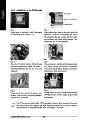
... the push pin is inserted as a result of hardening of arrow sign on the motherboard.Pressing down the push pins diagonally. Fig. 6 Finally, please attach the power connector of the installed CPU. GA-965P-DS3P Motherboard - 14 - To prevent such an occurrence, it is complete. Fig. 2 (Turning the push pin along the direction of arrow... paste. Fig. 4 Please make sure the push pins aim to the CPU cooler installation section of the user manual) Fig. 5 Please check the back of motherboard after installing.
... the push pin is inserted as a result of hardening of arrow sign on the motherboard.Pressing down the push pins diagonally. Fig. 6 Finally, please attach the power connector of the installed CPU. GA-965P-DS3P Motherboard - 14 - To prevent such an occurrence, it is complete. Fig. 2 (Turning the push pin along the direction of arrow... paste. Fig. 4 Please make sure the push pins aim to the CPU cooler installation section of the user manual) Fig. 5 Please check the back of motherboard after installing.
Manual
Page 15
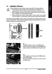
... has a notch, so the DIMM memory module can be inserted only in one direction. Memory modules have a foolproof insertion design. The motherboard supports DDRII memory modules, whereby BIOS will automatically detect memory capacity and specifications. Fig.2 Close the plastic clip at both edges of the DIMM... sockets to insert the module, please switch the direction. It is supported by the motherboard. A memory module can only fit in one direction. Then push it down. Hardware Installation Please make sure that they can differ with...
... has a notch, so the DIMM memory module can be inserted only in one direction. Memory modules have a foolproof insertion design. The motherboard supports DDRII memory modules, whereby BIOS will automatically detect memory capacity and specifications. Fig.2 Close the plastic clip at both edges of the DIMM... sockets to insert the module, please switch the direction. It is supported by the motherboard. A memory module can only fit in one direction. Then push it down. Hardware Installation Please make sure that they can differ with...
Manual
Page 16
... following explanations due to the limitation of memory bus will appear during POST. DS/SS DS/SS DDRII3 DS/SS - GA-965P-DS3P Motherboard - 16 - To enable Dual Channel mode with two or four memory modules (it is configured to be enabled if only..."--": Empty) 2 memory modules 4 memory modules DDRII1 DS/SS - DS/SS DDRII4 - English Dual Channel Memory Configuration The GA-965P-DS3P supports the Dual Channel Technology. The GA-965P-DS3P includes 4 DIMM sockets, and each Channel has two DIMM sockets as following is installed. 2. Intel® Flex Memory Technology...
... following explanations due to the limitation of memory bus will appear during POST. DS/SS DS/SS DDRII3 DS/SS - GA-965P-DS3P Motherboard - 16 - To enable Dual Channel mode with two or four memory modules (it is configured to be enabled if only..."--": Empty) 2 memory modules 4 memory modules DDRII1 DS/SS - DS/SS DDRII4 - English Dual Channel Memory Configuration The GA-965P-DS3P supports the Dual Channel Technology. The GA-965P-DS3P includes 4 DIMM sockets, and each Channel has two DIMM sockets as following is installed. 2. Intel® Flex Memory Technology...
Manual
Page 17
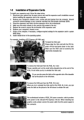
... can also press the latch on the card are fully seated in the computer. 2. Press the expansion card firmly into the expansion slot in the motherboard. 4. Remove your computer's chassis cover. 7. The motherboard includes a PCIE_12V power connector, which provides extra power to the onboard PCI Express x16 slot.
... can also press the latch on the card are fully seated in the computer. 2. Press the expansion card firmly into the expansion slot in the motherboard. 4. Remove your computer's chassis cover. 7. The motherboard includes a PCIE_12V power connector, which provides extra power to the onboard PCI Express x16 slot.

Manual
Page 18
... like CD-ROM, walkman etc. LAN Port The provided Internet connection is capable of 10/100/ 1000 Mbps. Line In The default Line In jack. GA-965P-DS3P Motherboard - 18 - Surround side speakers can be connected to Surround Speaker Out (Rear Speaker Out) jack. COM (Serial Port) Connects to the lower port (purple). have...
... like CD-ROM, walkman etc. LAN Port The provided Internet connection is capable of 10/100/ 1000 Mbps. Line In The default Line In jack. GA-965P-DS3P Motherboard - 18 - Surround side speakers can be connected to Surround Speaker Out (Rear Speaker Out) jack. COM (Serial Port) Connects to the lower port (purple). have...
Manual
Page 20
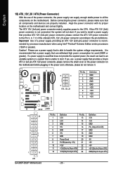
..., please do not remove it. 8 4 5 1 ATX_12V_2X Pin No. 1 2 3 4 5 6 7 8 Definition GND GND GND GND +12V +12V +12V +12V 12 24 1 13 ATX GA-965P-DS3P Motherboard Pin No. 1 2 3 4 5 6 7 8 9 10 11 12 Definition 3.3V 3.3V GND +5V GND +5V GND Power Good 5V SB(stand by processor manufacturer when using Intel®...; Pentium® Extreme Edition series processors (130W or greater). Align the power connector with its proper location on the motherboard before plugging in the power cord; mended by +5V) +12V +12V(Only for 24-pin ATX) 3.3V(Only for 24-pin ATX)...
..., please do not remove it. 8 4 5 1 ATX_12V_2X Pin No. 1 2 3 4 5 6 7 8 Definition GND GND GND GND +12V +12V +12V +12V 12 24 1 13 ATX GA-965P-DS3P Motherboard Pin No. 1 2 3 4 5 6 7 8 9 10 11 12 Definition 3.3V 3.3V GND +5V GND +5V GND Power Good 5V SB(stand by processor manufacturer when using Intel®...; Pentium® Extreme Edition series processors (130W or greater). Align the power connector with its proper location on the motherboard before plugging in the power cord; mended by +5V) +12V +12V(Only for 24-pin ATX) 3.3V(Only for 24-pin ATX)...
Manual
Page 22
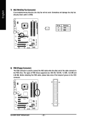
Before attaching the FDD cable, please take note of FDD drives supported are: 360 KB, 720 KB, 1.2 MB, 1.44 MB and 2.88 MB. English 7) NB_FAN (Chip Fan Connector) If you installed wrong direction, the chip fan will damage the chip fan. (Usually black cable is used to connect the FDD cable while the other end of the cable connects to the FDD drive. The types of the foolproof groove in the FDD connector. 34 33 GA-965P-DS3P Motherboard 2 1 - 22 - Definition 1 1 +12V 2 GND 8) FDD (Floppy Connector) The FDD connector is GND) Pin No. Sometimes will not work.
Before attaching the FDD cable, please take note of FDD drives supported are: 360 KB, 720 KB, 1.2 MB, 1.44 MB and 2.88 MB. English 7) NB_FAN (Chip Fan Connector) If you installed wrong direction, the chip fan will damage the chip fan. (Usually black cable is used to connect the FDD cable while the other end of the cable connects to the FDD drive. The types of the foolproof groove in the FDD connector. 34 33 GA-965P-DS3P Motherboard 2 1 - 22 - Definition 1 1 +12V 2 GND 8) FDD (Floppy Connector) The FDD connector is GND) Pin No. Sometimes will not work.
Manual
Page 24
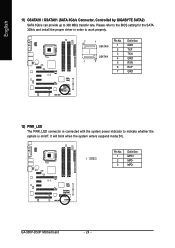
... 1 GND 2 TXP 3 TXN GSATAII1 4 GND 1 7 5 RXN 6 RXP 7 GND 12) PWR_LED The PWR_LED connector is connected with the system power indicator to work properly. 7 1 Pin No. GA-965P-DS3P Motherboard - 24 - English 11) GSATAII0 / GSATAII1 (SATA 3Gb/s Connector, Controlled by GIGABYTE SATA2) SATA 3Gb/s can provide up to 300 MB/s transfer rate. Definition 1 MPD+ 1 2 MPD- 3 MPD-
... 1 GND 2 TXP 3 TXN GSATAII1 4 GND 1 7 5 RXN 6 RXP 7 GND 12) PWR_LED The PWR_LED connector is connected with the system power indicator to work properly. 7 1 Pin No. GA-965P-DS3P Motherboard - 24 - English 11) GSATAII0 / GSATAII1 (SATA 3Gb/s Connector, Controlled by GIGABYTE SATA2) SATA 3Gb/s can provide up to 300 MB/s transfer rate. Definition 1 MPD+ 1 2 MPD- 3 MPD-
Manual
Page 26
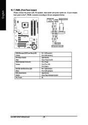
...: Normal Close: Power On/Off Pin 1: Power Pin 2- Pin 3: NC Pin 4: Data(-) Pin 1: LED anode(+) Pin 2: LED cathode(-) Open: Normal Close: Reset Hardware System NC GA-965P-DS3P Motherboard - 26 - English 15) F_PANEL (Front Panel Jumper) Please connect the power LED, PC speaker, reset switch and power switch etc.
...: Normal Close: Power On/Off Pin 1: Power Pin 2- Pin 3: NC Pin 4: Data(-) Pin 1: LED anode(+) Pin 2: LED cathode(-) Open: Normal Close: Reset Hardware System NC GA-965P-DS3P Motherboard - 26 - English 15) F_PANEL (Front Panel Jumper) Please connect the power LED, PC speaker, reset switch and power switch etc.
Manual
Page 28
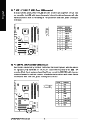
... features like high speed, high bandwidth and hot plug. Definition 2 10 1 TPA+ 1 9 2 TPA- 3 GND 4 GND 5 TPB+ 6 TPB- 7 Power (12V) 8 Power (12V) 9 No Pin 10 GND GA-965P-DS3P Motherboard - 28 -
... features like high speed, high bandwidth and hot plug. Definition 2 10 1 TPA+ 1 9 2 TPA- 3 GND 4 GND 5 TPB+ 6 TPB- 7 Power (12V) 8 Power (12V) 9 No Pin 10 GND GA-965P-DS3P Motherboard - 28 -

Manual
Page 30
English GA-965P-DS3P Motherboard - 30 -
English GA-965P-DS3P Motherboard - 30 -


