Manual
Page 10
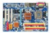
... Chipset Š Southbridge: Intel® ICH7 LAN Š Onboard RTL8111B chip (10/100/1000Mbit) Audio Š Onboard Realtek ALC888 CODEC chip Š Supports High Definition Audio Š Supports 2 / 4 / 6 / 8 channel audio Š Supports S/PDIF In/Out connection Š Supports CD In connection Storage Š Intel® ICH7 - 1 FDD connector,... In connector Š 1 S/PDIF In/Out connector Š 2 USB 2.0/1.1 connectors for additional 4 USB 2.0/1.1 ports by cables Š 1 power LED connector Š 1 Chassis Intrusion connector GA-946GZ-DS3 (rev. 2.0) Motherboard - 10 -
... Chipset Š Southbridge: Intel® ICH7 LAN Š Onboard RTL8111B chip (10/100/1000Mbit) Audio Š Onboard Realtek ALC888 CODEC chip Š Supports High Definition Audio Š Supports 2 / 4 / 6 / 8 channel audio Š Supports S/PDIF In/Out connection Š Supports CD In connection Storage Š Intel® ICH7 - 1 FDD connector,... In connector Š 1 S/PDIF In/Out connector Š 2 USB 2.0/1.1 connectors for additional 4 USB 2.0/1.1 ports by cables Š 1 power LED connector Š 1 Chassis Intrusion connector GA-946GZ-DS3 (rev. 2.0) Motherboard - 10 -

Manual
Page 19
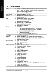
... withstand high power consumption be used (300W or greater). otherwise, please do not remove it. 3 4 1 2 ATX_12V Pin No. 1 2 3 4 Definition GND GND +12V +12V 12 24 1 13 ATX Pin No. 1 2 3 4 5 6 7 8 9 10 11 12 Definition 3.3V 3.3V GND +5V GND +5V GND Power Good 5V SB(stand by +5V) +12V +12V(Only for 24...-pin ATX) 3.3V(Only for 24-pin ATX) Pin No. 13 14 15 16 17 18 19 20 21 22 23 24 Definition 3.3V -12V GND PS_ON(soft On/Off) GND GND GND -5V +5V +5V +5V (Only for 24-pin ATX) GND(Only for 24-pin ATX...
... withstand high power consumption be used (300W or greater). otherwise, please do not remove it. 3 4 1 2 ATX_12V Pin No. 1 2 3 4 Definition GND GND +12V +12V 12 24 1 13 ATX Pin No. 1 2 3 4 5 6 7 8 9 10 11 12 Definition 3.3V 3.3V GND +5V GND +5V GND Power Good 5V SB(stand by +5V) +12V +12V(Only for 24...-pin ATX) 3.3V(Only for 24-pin ATX) Pin No. 13 14 15 16 17 18 19 20 21 22 23 24 Definition 3.3V -12V GND PS_ON(soft On/Off) GND GND GND -5V +5V +5V +5V (Only for 24-pin ATX) GND(Only for 24-pin ATX...
Manual
Page 20
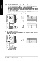
Most coolers are designed with color-coded power connector wires. The black connector wire is GND) Pin No. Sometimes will not work. Definition 1 GND 1 2 +12V 3 NC GA-946GZ-DS3 (rev. 2.0) Motherboard - 20 - Remember to connect the CPU/system fan cable to the CPU_FAN/SYS_FAN connector to prevent CPU damage or system hanging caused by ...
Most coolers are designed with color-coded power connector wires. The black connector wire is GND) Pin No. Sometimes will not work. Definition 1 GND 1 2 +12V 3 NC GA-946GZ-DS3 (rev. 2.0) Motherboard - 20 - Remember to connect the CPU/system fan cable to the CPU_FAN/SYS_FAN connector to prevent CPU damage or system hanging caused by ...
Manual
Page 22
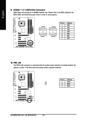
Pin No. GA-946GZ-DS3 (rev. 2.0) Motherboard - 22 - SATAII0 7 17 SATAII2 1 1 71 7 SATAII1 SATAII3 Pin No. 1 2 3 4 5 6 7 Definition GND TXP TXN GND RXN RXP GND 10) PWR_LED The PWR_LED connector is connected with the system power indicator to 300MB/s transfer rate. It will blink when the system enters suspend mode(S1). Definition 1 MPD+ 1 2 MPD- 3 MPD- English 9) SATAII0...
Pin No. GA-946GZ-DS3 (rev. 2.0) Motherboard - 22 - SATAII0 7 17 SATAII2 1 1 71 7 SATAII1 SATAII3 Pin No. 1 2 3 4 5 6 7 Definition GND TXP TXN GND RXN RXP GND 10) PWR_LED The PWR_LED connector is connected with the system power indicator to 300MB/s transfer rate. It will blink when the system enters suspend mode(S1). Definition 1 MPD+ 1 2 MPD- 3 MPD- English 9) SATAII0...
Manual
Page 23
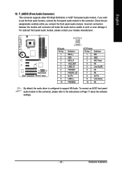
... while you wish to use the front audio function, connect the front panel audio module to this connector, please refer to this connector. Hardware Installation Definition 1 MIC 2 GND 3 MIC Power 4 NC 5 Line Out (R) 6 NC 7 NC 8 No Pin 9 Line Out (L) 10 NC By ... For optional front panel audio module, please contact your chassis manufacturer. 10 9 HD Audio: Pin No. 1 2 3 4 5 6 7 8 9 10 2 Definition MIC2_L GND MIC2_R -ACZ_DET LINE2_R FSENSE1 FAUDIO_JD No Pin LINE2_L FSENSE2 1 AC'97 Audio: Pin No. Incorrect connection between the module and connector will make...
... while you wish to use the front audio function, connect the front panel audio module to this connector, please refer to this connector. Hardware Installation Definition 1 MIC 2 GND 3 MIC Power 4 NC 5 Line Out (R) 6 NC 7 NC 8 No Pin 9 Line Out (L) 10 NC By ... For optional front panel audio module, please contact your chassis manufacturer. 10 9 HD Audio: Pin No. 1 2 3 4 5 6 7 8 9 10 2 Definition MIC2_L GND MIC2_R -ACZ_DET LINE2_R FSENSE1 FAUDIO_JD No Pin LINE2_L FSENSE2 1 AC'97 Audio: Pin No. Incorrect connection between the module and connector will make...
Manual
Page 25
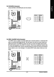
Use this feature only when your local dealer. 26 15 Pin No. 1 2 3 4 5 6 Definition Power No Pin SPDIF SPDIFI GND GND - 25 - Definition 1 CD-L 2 GND 1 3 GND 4 CD-R 14) SPDIF_IO (S/PDIF In/Out Connector) The S/PDIF output is capable of the SPDIF_IO connector. For optional S/PDIF cable, please contact ...
Use this feature only when your local dealer. 26 15 Pin No. 1 2 3 4 5 6 Definition Power No Pin SPDIF SPDIFI GND GND - 25 - Definition 1 CD-L 2 GND 1 3 GND 4 CD-R 14) SPDIF_IO (S/PDIF In/Out Connector) The S/PDIF output is capable of the SPDIF_IO connector. For optional S/PDIF cable, please contact ...
Manual
Page 26
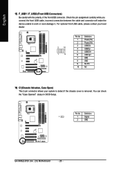
Definition 1 1 Signal 2 GND GA-946GZ-DS3 (rev. 2.0) Motherboard - 26 - Pin No. For optional front USB cable, please contact your local dealer. 2 10 1 9 Pin No. 1 2 3 4 5 6 7 8 9 10 Definition Power (5V) Power (5V) USB DXUSB DyUSB DX+ USB Dy+ GND GND No Pin NC 16) CI (Chassis Intrusion, Case Open) This 2-pin connector allows ...
Definition 1 1 Signal 2 GND GA-946GZ-DS3 (rev. 2.0) Motherboard - 26 - Pin No. For optional front USB cable, please contact your local dealer. 2 10 1 9 Pin No. 1 2 3 4 5 6 7 8 9 10 Definition Power (5V) Power (5V) USB DXUSB DyUSB DX+ USB Dy+ GND GND No Pin NC 16) CI (Chassis Intrusion, Case Open) This 2-pin connector allows ...
