
Manual
Page 1
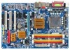
GA-946-DS3/ GA-946-S3 LGA775 socket motherboard for Intel® CoreTM processor family/ Intel® Pentium® processor family/Intel® Celeron® processor family User's Manual Rev. 3301 12ME-946DS3-3301R * The WEEE marking on the product indicates this product must not be disposed of with user's other household waste and must be handed over to a designated collection point for the recycling of waste electrical and electronic equipment!! * The WEEE marking applies only in European Union's member states.
GA-946-DS3/ GA-946-S3 LGA775 socket motherboard for Intel® CoreTM processor family/ Intel® Pentium® processor family/Intel® Celeron® processor family User's Manual Rev. 3301 12ME-946DS3-3301R * The WEEE marking on the product indicates this product must not be disposed of with user's other household waste and must be handed over to a designated collection point for the recycling of waste electrical and electronic equipment!! * The WEEE marking applies only in European Union's member states.

Manual
Page 2
Motherboard GA-946-DS3/GA-946-S3 Jun. 1, 2007 Motherboard GA-946-DS3/GA-946-S3 Jun. 1, 2007
Motherboard GA-946-DS3/GA-946-S3 Jun. 1, 2007 Motherboard GA-946-DS3/GA-946-S3 Jun. 1, 2007
Manual
Page 3
... prior notice. For product-related information, check on our website at: http://www.gigabyte.com.tw Identifying Your Motherboard Revision The revision number on your motherboard revision before updating motherboard BIOS, drivers, or when looking for technical information. by GIGA-BYTE TECHNOLOGY CO...., LTD as the exclu- Disclaimer Information in this manual may be made by GIGABYTE without GIGABYTE's prior written permission. Check your motherboard looks like this manual may be reproduced, copied, translated, transmitted, or published in this manual is ...
... prior notice. For product-related information, check on our website at: http://www.gigabyte.com.tw Identifying Your Motherboard Revision The revision number on your motherboard revision before updating motherboard BIOS, drivers, or when looking for technical information. by GIGA-BYTE TECHNOLOGY CO...., LTD as the exclu- Disclaimer Information in this manual may be made by GIGABYTE without GIGABYTE's prior written permission. Check your motherboard looks like this manual may be reproduced, copied, translated, transmitted, or published in this manual is ...
Manual
Page 4
Table of Contents OptionalItems ...6 Box Contents ...6 GA-946-DS3/S3 Motherboard Layout 7 Block Diagram ...8 Chapter 1 Hardware Installation 9 1-1 Installation Precautions 9 1-2 Product Specifications 10 1-3 Installing the CPU and CPU Cooler 13 1-3-1 Installing the CPU 13 1-3-2 Installing the CPU ...
Table of Contents OptionalItems ...6 Box Contents ...6 GA-946-DS3/S3 Motherboard Layout 7 Block Diagram ...8 Chapter 1 Hardware Installation 9 1-1 Installation Precautions 9 1-2 Product Specifications 10 1-3 Installing the CPU and CPU Cooler 13 1-3-1 Installing the CPU 13 1-3-2 Installing the CPU ...
Manual
Page 6
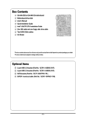
... (Part No. 12CR1-1UB030-21/R) SATA bracket (Part No. 12CF1-3SATPW-11R ) S/PDIF in and out cable (Part No. 12CR1-1SPINO-11/R) - 6 - Box Contents GA-946-DS3 or GA-946-S3 motherboard Motherboard driver disk User's Manual Quick Installation Guide Intel® LGA775 CPU Installation Guide One IDE cable and one floppy disk drive cable Two SATA...
... (Part No. 12CR1-1UB030-21/R) SATA bracket (Part No. 12CF1-3SATPW-11R ) S/PDIF in and out cable (Part No. 12CR1-1SPINO-11/R) - 6 - Box Contents GA-946-DS3 or GA-946-S3 motherboard Motherboard driver disk User's Manual Quick Installation Guide Intel® LGA775 CPU Installation Guide One IDE cable and one floppy disk drive cable Two SATA...

Manual
Page 7
GA-946-DS3/S3 Motherboard Layout KB_MS ATX_12V LGA775 CPU_FAN GA-946-DS3/S3 COMA LPT PWR_FAN USB USB LAN AUDIO1 AUDIO2 RTL8111B CODEC F_AUDIO DDRII1 DDRII2 DDRII3 DDRII4 NB_FAN Intel® 946GZ PCIE_3 ATX PCIE_16 PCIE_1 PCIE_2 PCI1 PCI2 CLR_CMOS Intel® ICH7 BAT SATAII0 SATAII2 SATAII1 SATAII3 BIOS SYS_FAN IT8718 PCI3 CI FDD IDE1 PWR_LED F_PANEL CD_IN SPDIF_IO F_USB1 F_USB2 "*" Only the GA-946-DS3 adopts All-Solid Capacitor design. - 7 -
GA-946-DS3/S3 Motherboard Layout KB_MS ATX_12V LGA775 CPU_FAN GA-946-DS3/S3 COMA LPT PWR_FAN USB USB LAN AUDIO1 AUDIO2 RTL8111B CODEC F_AUDIO DDRII1 DDRII2 DDRII3 DDRII4 NB_FAN Intel® 946GZ PCIE_3 ATX PCIE_16 PCIE_1 PCIE_2 PCI1 PCI2 CLR_CMOS Intel® ICH7 BAT SATAII0 SATAII2 SATAII1 SATAII3 BIOS SYS_FAN IT8718 PCI3 CI FDD IDE1 PWR_LED F_PANEL CD_IN SPDIF_IO F_USB1 F_USB2 "*" Only the GA-946-DS3 adopts All-Solid Capacitor design. - 7 -

Manual
Page 9
...metal leads or connectors. • It is best to wear an electrostatic discharge (ESD) wrist strap when handling electronic components such as a motherboard, CPU or memory. Prior to installation, carefully read the user's manual and follow these procedures: • Prior to installation, do not remove or... Always remove the AC power by your hands dry and first touch a metal object to eliminate static electricity. • Prior to installing the motherboard, please have it on top of an antistatic pad or within the computer casing. • Do not place the computer system on an uneven...
...metal leads or connectors. • It is best to wear an electrostatic discharge (ESD) wrist strap when handling electronic components such as a motherboard, CPU or memory. Prior to installation, carefully read the user's manual and follow these procedures: • Prior to installation, do not remove or... Always remove the AC power by your hands dry and first touch a metal object to eliminate static electricity. • Prior to installing the motherboard, please have it on top of an antistatic pad or within the computer casing. • Do not place the computer system on an uneven...
Manual
Page 10
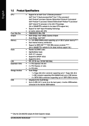
GA-946-DS3/S3 Motherboard - 10 - English 1-2 Product Specifications CPU Front Side Bus Chipset...Intel® Pentium® 4 processor/ Intel® Celeron® D processor in the LGA 775 package (Go to GIGABYTE's website for the latest CPU support list.) Š Support for Intel® Hyper-Threading Technology Š L2 cache varies...138; Dual channel memory architecture Š Support for DDR2 667 (Note 2)/533 MHz memory modules (Note 3) (Go to GIGABYTE's website for the latest memory support list.) Š Realtek ALC889A codec Š High Definition Audio Š 2/4/5.1/7.1-channel Š...
GA-946-DS3/S3 Motherboard - 10 - English 1-2 Product Specifications CPU Front Side Bus Chipset...Intel® Pentium® 4 processor/ Intel® Celeron® D processor in the LGA 775 package (Go to GIGABYTE's website for the latest CPU support list.) Š Support for Intel® Hyper-Threading Technology Š L2 cache varies...138; Dual channel memory architecture Š Support for DDR2 667 (Note 2)/533 MHz memory modules (Note 3) (Go to GIGABYTE's website for the latest memory support list.) Š Realtek ALC889A codec Š High Definition Audio Š 2/4/5.1/7.1-channel Š...

Manual
Page 12
GA-946-DS3/S3 Motherboard - 12 - English Unique Features Bundled Software Operating System Form Factor Š Support for @BIOS Š Support for Download Center Š Support for Q-Flash Š Support ... to Page 16 for system usage and therefore the actual memory size is reserved for more information.) (Note 4) Available functions in Easytune may differ by motherboard model.
GA-946-DS3/S3 Motherboard - 12 - English Unique Features Bundled Software Operating System Form Factor Š Support for @BIOS Š Support for Download Center Š Support for Q-Flash Š Support ... to Page 16 for system usage and therefore the actual memory size is reserved for more information.) (Note 4) Available functions in Easytune may differ by motherboard model.

Manual
Page 13
...8226; An operating system that is not recom- If you begin to install the CPU: • Make sure that the motherboard supports the CPU. (Go to GIGABYTE's website for the peripherals. LGA775 CPU Socket Alignment Key LGA 775 CPU Alignment Key Pin One Corner of the CPU Socket...please do so according to your hardware specifications including the CPU, graphics card, memory, hard drive, etc. Locate the alignment keys on the motherboard CPU socket and the notches on enabling the HT Technology.) 1-3-1 Installing the CPU A. Notch Triangle Pin One Marking on the CPU Hardware Installation...
...8226; An operating system that is not recom- If you begin to install the CPU: • Make sure that the motherboard supports the CPU. (Go to GIGABYTE's website for the peripherals. LGA775 CPU Socket Alignment Key LGA 775 CPU Alignment Key Pin One Corner of the CPU Socket...please do so according to your hardware specifications including the CPU, graphics card, memory, hard drive, etc. Locate the alignment keys on the motherboard CPU socket and the notches on enabling the HT Technology.) 1-3-1 Installing the CPU A. Notch Triangle Pin One Marking on the CPU Hardware Installation...
Manual
Page 14
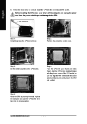
... the CPU with the socket alignment keys) and gently insert the CPU into position. English B. CPU Socket Lever Step 1: Completely raise the CPU socket lever. GA-946-DS3/S3 Motherboard - 14 - Step 2: Remove the protective socket cover. Before installing the CPU, make sure to turn off the computer and unplug the power cord from...
... the CPU with the socket alignment keys) and gently insert the CPU into position. English B. CPU Socket Lever Step 1: Completely raise the CPU socket lever. GA-946-DS3/S3 Motherboard - 14 - Step 2: Remove the protective socket cover. Before installing the CPU, make sure to turn off the computer and unplug the power cord from...

Manual
Page 15
... 6: Finally, attach the power connector of arrow is to remove the cooler, on the contrary, is to the CPU fan header (CPU_FAN) on the motherboard. Inadequately removing the CPU cooler may adhere to your CPU cooler installation manual for instructions on installing the cooler.) Step 5: After the installation, check the ... of the CPU cooler to install.) Step 3: Place the cooler atop the CPU, aligning the four push pins through the pin holes on the motherboard. If the push pin is inserted as the example cooler.) Step 1: Apply an even and thin layer of thermal grease on the surface of ...
... 6: Finally, attach the power connector of arrow is to remove the cooler, on the contrary, is to the CPU fan header (CPU_FAN) on the motherboard. Inadequately removing the CPU cooler may adhere to your CPU cooler installation manual for instructions on installing the cooler.) Step 5: After the installation, check the ... of the CPU cooler to install.) Step 3: Place the cooler atop the CPU, aligning the four push pins through the pin holes on the motherboard. If the push pin is inserted as the example cooler.) Step 1: Apply an even and thin layer of thermal grease on the surface of ...
Manual
Page 16
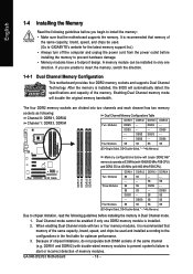
... memory mode will automatically detect the specifications and capacity of the same capacity, brand, speed, and chips be used . (Go to GIGABYTE's website for optimum performance. 3. SS SS DS/SS SS (SS=Single-Sided, DS=Double-Sided, "- -"=No Memory) Memory configurations... memory is installed. 2. When enabling Dual Channel mode with two or four memory modules, it is recommended that memory of the same channel (e.g. GA-946-DS3/S3 Motherboard - 16 - It is recommended that memory of the memory. A memory module can be enabled if only one direction. DS/SS DDRII4 -...
... memory mode will automatically detect the specifications and capacity of the same capacity, brand, speed, and chips be used . (Go to GIGABYTE's website for optimum performance. 3. SS SS DS/SS SS (SS=Single-Sided, DS=Double-Sided, "- -"=No Memory) Memory configurations... memory is installed. 2. When enabling Dual Channel mode with two or four memory modules, it is recommended that memory of the same channel (e.g. GA-946-DS3/S3 Motherboard - 16 - It is recommended that memory of the memory. A memory module can be enabled if only one direction. DS/SS DDRII4 -...

Manual
Page 17
... of the socket will snap into the memory socket. Step 2: The clips at both ends of the memory module. Place the memory module on this motherboard. Follow the steps below to correctly install your fingers on the memory and insert it can only fit in the memory sockets. Spread the retaining...
... of the socket will snap into the memory socket. Step 2: The clips at both ends of the memory module. Place the memory module on this motherboard. Follow the steps below to correctly install your fingers on the memory and insert it can only fit in the memory sockets. Spread the retaining...
Manual
Page 18
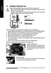
... the end of the PCI Express x16 slot to install an expansion card: • Make sure the motherboard supports the expansion card. Make sure the graphics card is fully seated in the expansion slot. 1. GA-946-DS3/S3 Motherboard - 18 - English 1-5 Installing an Expansion Card Read the following guidelines before installing an expansion card to...
... the end of the PCI Express x16 slot to install an expansion card: • Make sure the motherboard supports the expansion card. Make sure the graphics card is fully seated in the expansion slot. 1. GA-946-DS3/S3 Motherboard - 18 - English 1-5 Installing an Expansion Card Read the following guidelines before installing an expansion card to...

Manual
Page 19
... configuration. • When removing the cable connected to prevent an electrical short inside the cable connector. - 19 - Do not rock it straight out from the motherboard. • When removing the cable, pull it side to side to a back panel connector, first remove the cable from your device and then remove it...
... configuration. • When removing the cable connected to prevent an electrical short inside the cable connector. - 19 - Do not rock it straight out from the motherboard. • When removing the cable, pull it side to side to a back panel connector, first remove the cable from your device and then remove it...

Manual
Page 20
Microphones must be reconfigured to connect front speakers in jack. GA-946-DS3/S3 Motherboard - 20 - Line Out Jack (Green) The default line out jack. This jack can be connected to this audio jack for line in jack. In addition ...
Microphones must be reconfigured to connect front speakers in jack. GA-946-DS3/S3 Motherboard - 20 - Line Out Jack (Green) The default line out jack. This jack can be connected to this audio jack for line in jack. In addition ...
Manual
Page 21
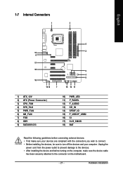
... 11) F_PANEL 12) F_AUDIO 13) CD_IN 14) SPDIF_IO 15) F_USB1/F_USB2 16) CI 17) CLR_CMOS 18) BAT Read the following guidelines before turning on the motherboard. - 21 -
... 11) F_PANEL 12) F_AUDIO 13) CD_IN 14) SPDIF_IO 15) F_USB1/F_USB2 16) CI 17) CLR_CMOS 18) BAT Read the following guidelines before turning on the motherboard. - 21 -

Manual
Page 22
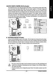
Connect the power supply cable to all devices are properly installed. If a power supply is turned off and all the components on the motherboard. English 1/2) ATX_12V_2X/ATX (2x2 12V Power Connector and 2x12 Main Power Connector) With the use of the power connector, the power supply can supply ...-12V GND PS_ON(soft On/Off) GND GND GND -5V +5V +5V +5V (Only for 2x12-pin ATX) GND (Only for 2x12-pin ATX) GA-946-DS3/S3 Motherboard - 22 - If the 12V power connector is not connected, the computer will not start. • To meet expansion requirements, it is compatible with power supplies...
Connect the power supply cable to all devices are properly installed. If a power supply is turned off and all the components on the motherboard. English 1/2) ATX_12V_2X/ATX (2x2 12V Power Connector and 2x12 Main Power Connector) With the use of the power connector, the power supply can supply ...-12V GND PS_ON(soft On/Off) GND GND GND -5V +5V +5V +5V (Only for 2x12-pin ATX) GND (Only for 2x12-pin ATX) GA-946-DS3/S3 Motherboard - 22 - If the 12V power connector is not connected, the computer will not start. • To meet expansion requirements, it is compatible with power supplies...
Manual
Page 23
The motherboard supports CPU fan speed control, which requires the use of a CPU fan with color-coded power connector wires. Overheating may result in damage to the .... The fan header has a foolproof insertion design. A red power connector wire indicates a positive connection and requires a +12V voltage. English 3/4/5) CPU_FAN/SYS_FAN/PWR_FAN (Fan Headers) The motherboard has a 4-pin CPU fan header (CPU_FAN), a 3-pin system fan header (SYS_FAN), and a 3-pin power fan header (PWR_FAN). Most fans are designed with fan speed control...
The motherboard supports CPU fan speed control, which requires the use of a CPU fan with color-coded power connector wires. Overheating may result in damage to the .... The fan header has a foolproof insertion design. A red power connector wire indicates a positive connection and requires a +12V voltage. English 3/4/5) CPU_FAN/SYS_FAN/PWR_FAN (Fan Headers) The motherboard has a 4-pin CPU fan header (CPU_FAN), a 3-pin system fan header (SYS_FAN), and a 3-pin power fan header (PWR_FAN). Most fans are designed with fan speed control...


