Manual
Page 1
GA-945PL-DS3P/ GA-945PL-S3P Intel® CoreTM 2 Extreme dual-core / CoreTM 2 Duo / Intel® Pentium® D / Pentium® 4 / Celeron® D LGA775 Processor Motherboard User's Manual Rev. 6602 12ME-945PLDS3P-6602R * The WEEE marking on the product indicates this product must not be disposed of with user's other household waste and must be handed over to a designated collection point for the recycling of waste electrical and electronic equipment!! * The WEEE marking applies only in European Union's member states.
GA-945PL-DS3P/ GA-945PL-S3P Intel® CoreTM 2 Extreme dual-core / CoreTM 2 Duo / Intel® Pentium® D / Pentium® 4 / Celeron® D LGA775 Processor Motherboard User's Manual Rev. 6602 12ME-945PLDS3P-6602R * The WEEE marking on the product indicates this product must not be disposed of with user's other household waste and must be handed over to a designated collection point for the recycling of waste electrical and electronic equipment!! * The WEEE marking applies only in European Union's member states.
Manual
Page 2
Motherboard GA-945PL-DS3P/GA-945PL-S3P Apr. 3, 2007 Motherboard GA-945PL-DS3P/ GA-945PL-S3P Apr. 3, 2007
Motherboard GA-945PL-DS3P/GA-945PL-S3P Apr. 3, 2007 Motherboard GA-945PL-DS3P/ GA-945PL-S3P Apr. 3, 2007
Manual
Page 4
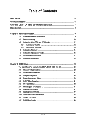
Table of Contents ItemChecklist ...6 OptionalAccessories ...6 GA-945PL-DS3P / GA-945PL-S3P Motherboard Layout 7 Block Diagram ...8 Chapter 1 Hardware Installation 9 1-1 Considerations Prior to Installation 9 1-2 Feature Summary 10 1-3 Installation of the CPU...1-5 Installation of Expansion Cards 16 1-6 I/O Back Panel Introduction 17 1-7 Connectors Introduction 18 Chapter 2 BIOS Setup 29 The Main Menu (For example: GA-945PL-DS3P BIOS Ver.: E1 30 2-1 Standard CMOS Features 32 2-2 Advanced BIOS Features 34 2-3 IntegratedPeripherals 36 2-4 Power Management Setup 39 2-5 PnP/PCI ...
Table of Contents ItemChecklist ...6 OptionalAccessories ...6 GA-945PL-DS3P / GA-945PL-S3P Motherboard Layout 7 Block Diagram ...8 Chapter 1 Hardware Installation 9 1-1 Considerations Prior to Installation 9 1-2 Feature Summary 10 1-3 Installation of the CPU...1-5 Installation of Expansion Cards 16 1-6 I/O Back Panel Introduction 17 1-7 Connectors Introduction 18 Chapter 2 BIOS Setup 29 The Main Menu (For example: GA-945PL-DS3P BIOS Ver.: E1 30 2-1 Standard CMOS Features 32 2-2 Advanced BIOS Features 34 2-3 IntegratedPeripherals 36 2-4 Power Management Setup 39 2-5 PnP/PCI ...
Manual
Page 7
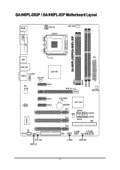
GA-945PL-DS3P / GA-945PL-S3P Motherboard Layout KB_MS ATX_12V LGA775 CPU_FAN GA-945PL-DS3P/GA-945PL-S3P COMA LPT ATX USB USB_LAN F_AUDIO AUDIO NB_FAN Intel® 945 RTL 8111B PCIE_3 PCIE_16 DDRII1 DDRII2 DDRII3 DDRII4 PWR_FAN CODEC PCIE_1 PCIE_2 IT8718 CI CD_IN SYS _FAN SPDIF_IO CLR_CMOS BATTERY Intel® ICH7 PCI1 SATAII0 BIOS PCI2 SATAII1 PCI3 FDD F_USB2 SATAII2 SATAII3 IDE1 F_PANEL F_USB1 PWR_LED - 7 -
GA-945PL-DS3P / GA-945PL-S3P Motherboard Layout KB_MS ATX_12V LGA775 CPU_FAN GA-945PL-DS3P/GA-945PL-S3P COMA LPT ATX USB USB_LAN F_AUDIO AUDIO NB_FAN Intel® 945 RTL 8111B PCIE_3 PCIE_16 DDRII1 DDRII2 DDRII3 DDRII4 PWR_FAN CODEC PCIE_1 PCIE_2 IT8718 CI CD_IN SYS _FAN SPDIF_IO CLR_CMOS BATTERY Intel® ICH7 PCI1 SATAII0 BIOS PCI2 SATAII1 PCI3 FDD F_USB2 SATAII2 SATAII3 IDE1 F_PANEL F_USB1 PWR_LED - 7 -
Manual
Page 8
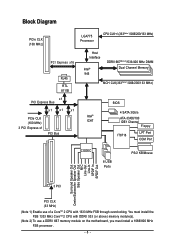
... Speaker Out MIC Line-Out Line-In SPDIF In SPDIF Out 3 PCI PCI CLK (33 MHz) (Note 1) Enable use a DDRII 667 memory module on the motherboard, you must install the FSB 1333 MHz CoreTM 2 CPU with DDRII 533 (or above) memory module(s). (Note 2) To use of a CoreTM 2 CPU with 1333 MHz...
... Speaker Out MIC Line-Out Line-In SPDIF In SPDIF Out 3 PCI PCI CLK (33 MHz) (Note 1) Enable use a DDRII 667 memory module on the motherboard, you must install the FSB 1333 MHz CoreTM 2 CPU with DDRII 533 (or above) memory module(s). (Note 2) To use of a CoreTM 2 CPU with 1333 MHz...

Manual
Page 9
...Gigabyte product. - 9 - It is switched off the computer and unplug its components. 5. Please verify that all cables and power connectors are no leftover screws or metal components placed on the motherboard or within a electrostatic shielding container. 5. Prior to the installation of the motherboard...within the computer casing. 6. English Chapter 1 Hardware Installation 1-1 Considerations Prior to Installation Preparing Your Computer The motherboard contains numerous delicate electronic circuits and components which can lead to damage to system components as well as physical ...
...Gigabyte product. - 9 - It is switched off the computer and unplug its components. 5. Please verify that all cables and power connectors are no leftover screws or metal components placed on the motherboard or within a electrostatic shielding container. 5. Prior to the installation of the motherboard...within the computer casing. 6. English Chapter 1 Hardware Installation 1-1 Considerations Prior to Installation Preparing Your Computer The motherboard contains numerous delicate electronic circuits and components which can lead to damage to system components as well as physical ...
Manual
Page 10
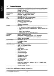
... connector Š 1 S/PDIF In/Out connector Š 2 USB 2.0/1.1 connectors for additional 4 USB 2.0/1.1 ports by cables Š 1 power LED connector Š 1 Chassis Intrusion connector "*" Only the GA-945PL-DS3P adopts All-Solid Capacitor design. GA-945PL-(D)S3P Motherboard - 10 -
... connector Š 1 S/PDIF In/Out connector Š 2 USB 2.0/1.1 connectors for additional 4 USB 2.0/1.1 ports by cables Š 1 power LED connector Š 1 Chassis Intrusion connector "*" Only the GA-945PL-DS3P adopts All-Solid Capacitor design. GA-945PL-(D)S3P Motherboard - 10 -
Manual
Page 11
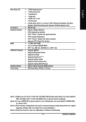
... memory frequency being reduced from the original frequency. (Please refer to to Page 15 for more information.) (Note 4) EasyTune functions may vary depending on the motherboard, you must install the FSB 1333 MHz CoreTM 2 CPU with 1333 MHz FSB through overclocking. Hardware Installation English Rear Panel I/O Š 1 PS/2 keyboard port Š....5cm x 19.3cm (Note 1) Enable use of a CoreTM 2 CPU with DDRII 533 (or above) memory module(s). (Note 2) To use a DDRII 667 memory module on different motherboards. - 11 -
... memory frequency being reduced from the original frequency. (Please refer to to Page 15 for more information.) (Note 4) EasyTune functions may vary depending on the motherboard, you must install the FSB 1333 MHz CoreTM 2 CPU with 1333 MHz FSB through overclocking. Hardware Installation English Rear Panel I/O Š 1 PS/2 keyboard port Š....5cm x 19.3cm (Note 1) Enable use of a CoreTM 2 CPU with DDRII 533 (or above) memory module(s). (Note 2) To use a DDRII 667 memory module on different motherboards. - 11 -
Manual
Page 12
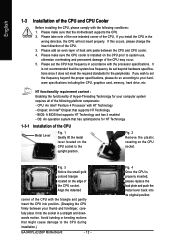
...card, memory, hard drive, etc. Fig. 3 Notice the small gold colored triangle located on the CPU socket to the CPU during installation.) GA-945PL-(D)S3P Motherboard - 12 - Align the indented corner of the CPU with the triangle and gently insert the CPU into position. (Grasping the CPU firmly between ... has optimizations for your thumb and forefinger, carefully place it enabled - Please make sure the CPU cooler is not recommended that the motherboard supports the CPU. 2. Please make sure that the system bus frequency be set the CPU host frequency in the wrong direction, the...
...card, memory, hard drive, etc. Fig. 3 Notice the small gold colored triangle located on the CPU socket to the CPU during installation.) GA-945PL-(D)S3P Motherboard - 12 - Align the indented corner of the CPU with the triangle and gently insert the CPU into position. (Grasping the CPU firmly between ... has optimizations for your thumb and forefinger, carefully place it enabled - Please make sure the CPU cooler is not recommended that the motherboard supports the CPU. 2. Please make sure that the system bus frequency be set the CPU host frequency in the wrong direction, the...
Manual
Page 13
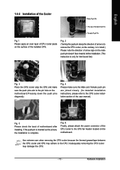
... CPU cooler atop the CPU and make sure the push pins aim to the pin hole on the motherboard. Inadequately removing the CPU cooler may adhere to the CPU fan header located on the motherboard.Pressing down the push pins diagonally. Use extreme care when removing the CPU cooler because the thermal... Push Pin The top of Female Push Pin Female Push Pin Fig.1 Please apply an even layer of CPU cooler paste on the surface of motherboard after installing.
... CPU cooler atop the CPU and make sure the push pins aim to the pin hole on the motherboard. Inadequately removing the CPU cooler may adhere to the CPU fan header located on the motherboard.Pressing down the push pins diagonally. Use extreme care when removing the CPU cooler because the thermal... Push Pin The top of Female Push Pin Female Push Pin Fig.1 Please apply an even layer of CPU cooler paste on the surface of motherboard after installing.
Manual
Page 14
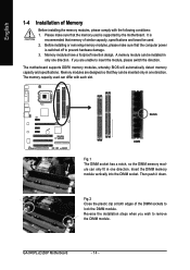
... modules, please make sure that the computer power is supported by the motherboard. Memory modules are unable to prevent hardware damage. 3. The motherboard supports DDRII memory modules, whereby BIOS will automatically detect memory capacity and specifications. The memory capacity used . 2. GA-945PL-(D)S3P Motherboard - 14 - Notch DDRII Fig.1 The DIMM socket has a notch, so the DIMM...
... modules, please make sure that the computer power is supported by the motherboard. Memory modules are unable to prevent hardware damage. 3. The motherboard supports DDRII memory modules, whereby BIOS will automatically detect memory capacity and specifications. The memory capacity used . 2. GA-945PL-(D)S3P Motherboard - 14 - Notch DDRII Fig.1 The DIMM socket has a notch, so the DIMM...
Manual
Page 16
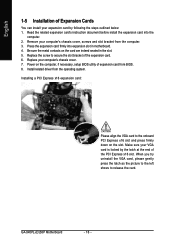
Power on the card are indeed seated in motherboard. 4. Read the related expansion card's instruction document before install the expansion card into expansion slot in the slot. 5. Installing a PCI Express x16 expansion card: Please ... gently press the latch as the picture to the left shows to the onboard PCI Express x16 slot and press firmly down on the slot. GA-945PL-(D)S3P Motherboard - 16 - English 1-5 Installation of Expansion Cards You can install your expansion card by the latch at the end of the PCI Express x16 slot. Press...
Power on the card are indeed seated in motherboard. 4. Read the related expansion card's instruction document before install the expansion card into expansion slot in the slot. 5. Installing a PCI Express x16 expansion card: Please ... gently press the latch as the picture to the left shows to the onboard PCI Express x16 slot and press firmly down on the slot. GA-945PL-(D)S3P Motherboard - 16 - English 1-5 Installation of Expansion Cards You can install your expansion card by the latch at the end of the PCI Express x16 slot. Press...
Manual
Page 18
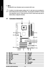
... audio setup steps for detailed software configuration information. 1-7 Connectors Introduction 1 3 6 11 16 13 14 4 1) ATX_12V 2) ATX (Power Connector) 3) CPU_FAN 4) SYS_FAN 5) PWR_FAN 6) NB_FAN 7) IDE1 8) FDD 9) SATAII0 / 1 / 2 / 3 GA-945PL-(D)S3P Motherboard 2 5 17 18 9 7 12 8 15 10 10) PWR_LED 11) F_AUDIO 12) F_PANEL 13) CD_IN 14) SPDIF_IO 15) F_USB1 / F_USB2 16) CI 17) CLR_CMOS 18) BATTERY - 18...
... audio setup steps for detailed software configuration information. 1-7 Connectors Introduction 1 3 6 11 16 13 14 4 1) ATX_12V 2) ATX (Power Connector) 3) CPU_FAN 4) SYS_FAN 5) PWR_FAN 6) NB_FAN 7) IDE1 8) FDD 9) SATAII0 / 1 / 2 / 3 GA-945PL-(D)S3P Motherboard 2 5 17 18 9 7 12 8 15 10 10) PWR_LED 11) F_AUDIO 12) F_PANEL 13) CD_IN 14) SPDIF_IO 15) F_USB1 / F_USB2 16) CI 17) CLR_CMOS 18) BATTERY - 18...

Manual
Page 19
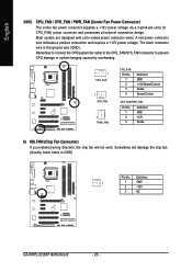
...- The ATX_12V power connector mainly supplies power to handle the system voltage requirements. Align the power connector with its proper location on the motherboard before plugging in the power cord; If the ATX_12V power connector is unable to all components and devices are properly installed. If you use... a 24-pin ATX power supply, please remove the small cover on the power connector on the motherboard and connect tightly. Please use a power supply that is recommended that a power supply that can withstand high power consumption be used that...
...- The ATX_12V power connector mainly supplies power to handle the system voltage requirements. Align the power connector with its proper location on the motherboard before plugging in the power cord; If the ATX_12V power connector is unable to all components and devices are properly installed. If you use... a 24-pin ATX power supply, please remove the small cover on the power connector on the motherboard and connect tightly. Please use a power supply that is recommended that a power supply that can withstand high power consumption be used that...
Manual
Page 20
... fan. (Usually black cable is the ground wire (GND). A red power connector wire indicates a positive connection and requires a +12V power voltage. Definition 1 1 GND 2 +12V 3 NC GA-945PL-(D)S3P Motherboard - 20 - The black connector wire is GND) Pin No. Sometimes will not work. English 3/4/5) CPU_FAN / SYS_FAN / PWR_FAN (Cooler Fan Power Connector) The cooler fan power...
... fan. (Usually black cable is the ground wire (GND). A red power connector wire indicates a positive connection and requires a +12V power voltage. Definition 1 1 GND 2 +12V 3 NC GA-945PL-(D)S3P Motherboard - 20 - The black connector wire is GND) Pin No. Sometimes will not work. English 3/4/5) CPU_FAN / SYS_FAN / PWR_FAN (Cooler Fan Power Connector) The cooler fan power...
Manual
Page 22
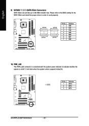
... whether the system is on/off. Definition 1 1 MPD+ 2 MPD- 3 MPD- English 9) SATAII0 / 1 / 2 / 3 (SATA 3Gb/s Connectors) SATA 3Gb/s can provide up to 300 MB/s transfer rate. GA-945PL-(D)S3P Motherboard - 22 -
... whether the system is on/off. Definition 1 1 MPD+ 2 MPD- 3 MPD- English 9) SATAII0 / 1 / 2 / 3 (SATA 3Gb/s Connectors) SATA 3Gb/s can provide up to 300 MB/s transfer rate. GA-945PL-(D)S3P Motherboard - 22 -
Manual
Page 24
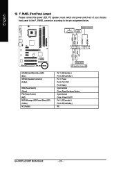
... HD+ HD- Pin 3: NC Pin 4: Data(-) Open: Normal Close: Reset Hardware System Open: Normal Close: Power On/Off Pin 1: LED anode(+) Pin 2: LED cathode(-) NC GA-945PL-(D)S3P Motherboard - 24 - Message LED/ Power/ Sleep LED Speaker Connector Power Switch MSG+ MSG- English 12) F_PANEL (Front Panel Jumper) Please connect the power LED, PC speaker...
... HD+ HD- Pin 3: NC Pin 4: Data(-) Open: Normal Close: Reset Hardware System Open: Normal Close: Power On/Off Pin 1: LED anode(+) Pin 2: LED cathode(-) NC GA-945PL-(D)S3P Motherboard - 24 - Message LED/ Power/ Sleep LED Speaker Connector Power Switch MSG+ MSG- English 12) F_PANEL (Front Panel Jumper) Please connect the power LED, PC speaker...
Manual
Page 26
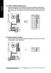
Definition 1 1 Signal 2 GND GA-945PL-(D)S3P Motherboard - 26 - English 15) F_USB1 / F_USB2 (Front USB Connectors) Be careful with the polarity of the front USB connector. You can check the "Case Opened" status ...
Definition 1 1 Signal 2 GND GA-945PL-(D)S3P Motherboard - 26 - English 15) F_USB1 / F_USB2 (Front USB Connectors) Be careful with the polarity of the front USB connector. You can check the "Case Opened" status ...
Manual
Page 28
English GA-945PL-(D)S3P Motherboard - 28 -
English GA-945PL-(D)S3P Motherboard - 28 -
Manual
Page 29
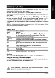
...changes General help window that describes the appropriate keys to use and the possible selections for Main Menu Main Menu The on the motherboard supplies the necessary power to quickly and easily update or backup BIOS without entering the operating system. @BIOS is potentially risky, ...please do it with caution and avoid inadequate operation that does not require users to boot to a new BIOS, either Gigabyte's Q-Flash or @BIOS utility can enter the BIOS setup screen by pressing "Ctrl + F1". The CMOS SETUP saves the configuration in system malfunction....
...changes General help window that describes the appropriate keys to use and the possible selections for Main Menu Main Menu The on the motherboard supplies the necessary power to quickly and easily update or backup BIOS without entering the operating system. @BIOS is potentially risky, ...please do it with caution and avoid inadequate operation that does not require users to boot to a new BIOS, either Gigabyte's Q-Flash or @BIOS utility can enter the BIOS setup screen by pressing "Ctrl + F1". The CMOS SETUP saves the configuration in system malfunction....


