Manual
Page 3
...., LTD. is designated by GIGA-BYTE TECHNOLOGY CO., LTD. Example: Disclaimer Information in this manual are legally registered to GIGABYTE UNITED INC. No part of this manual is the property of the product, read the Quick Installation Guide included with the...Support\Motherboard\Technology Guide page on your motherboard revision before updating motherboard BIOS, drivers, or when looking for technical information. For example, "REV: 1.0" means the revision of GIGABYTE branded motherboards. GIGABYTE UNITED INC. Changes to the specifications and features in this manual ...
...., LTD. is designated by GIGA-BYTE TECHNOLOGY CO., LTD. Example: Disclaimer Information in this manual are legally registered to GIGABYTE UNITED INC. No part of this manual is the property of the product, read the Quick Installation Guide included with the...Support\Motherboard\Technology Guide page on your motherboard revision before updating motherboard BIOS, drivers, or when looking for technical information. For example, "REV: 1.0" means the revision of GIGABYTE branded motherboards. GIGABYTE UNITED INC. Changes to the specifications and features in this manual ...
Manual
Page 4
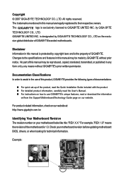
Table of Contents Box Contents ...6 OptionalItems ...6 GA-945PL-S3G Motherboard Layout 7 Block Diagram ...8 Chapter 1 Hardware Installation 9 1-1 Installation Precautions 9 1-2 Product Specifications 10 1-3 Installing the CPU and CPU Cooler 13... Memory 17 1-5 Installing an Expansion Card 18 1-6 Back Panel Connectors 19 1-7 Internal Connectors 20 Chapter 2 BIOS Setup 29 2-1 Startup Screen 30 2-2 The Main Menu 31 2-3 Standard CMOS Features 33 2-4 Advanced BIOS Features 35 2-5 IntegratedPeripherals 37 2-6 Power Management Setup 40 2-7 PnP/PCI Configurations 42 2-8 PC Health Status...
Table of Contents Box Contents ...6 OptionalItems ...6 GA-945PL-S3G Motherboard Layout 7 Block Diagram ...8 Chapter 1 Hardware Installation 9 1-1 Installation Precautions 9 1-2 Product Specifications 10 1-3 Installing the CPU and CPU Cooler 13... Memory 17 1-5 Installing an Expansion Card 18 1-6 Back Panel Connectors 19 1-7 Internal Connectors 20 Chapter 2 BIOS Setup 29 2-1 Startup Screen 30 2-2 The Main Menu 31 2-3 Standard CMOS Features 33 2-4 Advanced BIOS Features 35 2-5 IntegratedPeripherals 37 2-6 Power Management Setup 40 2-7 PnP/PCI Configurations 42 2-8 PC Health Status...
Manual
Page 5
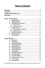
... 52 3-3 Driver CD Information 52 3-4 Hardware Information 53 3-5 Contact Us ...53 Chapter 4 Unique Features 55 4-1 Xpress Recovery2 55 4-2 BIOS Update Utilities 60 4-2-1 Updating the BIOS with the Q-Flash Utility 60 4-2-2 Updating the BIOS with the @BIOS Utility 63 4-3 EasyTune 5 ...65 4-4 Windows Vista ReadyBoost 66 Chapter 5 Appendix ...67 5-1 ConfiguringAudio Input and Output 67 5-1-1 Configuring 2/4/5.1-Channel...
... 52 3-3 Driver CD Information 52 3-4 Hardware Information 53 3-5 Contact Us ...53 Chapter 4 Unique Features 55 4-1 Xpress Recovery2 55 4-2 BIOS Update Utilities 60 4-2-1 Updating the BIOS with the Q-Flash Utility 60 4-2-2 Updating the BIOS with the @BIOS Utility 63 4-3 EasyTune 5 ...65 4-4 Windows Vista ReadyBoost 66 Chapter 5 Appendix ...67 5-1 ConfiguringAudio Input and Output 67 5-1-1 Configuring 2/4/5.1-Channel...

Manual
Page 8
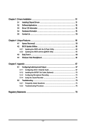
... Interface DDR2 667 (Note 2)/533/400 MHz Intel® 945 Dual Channel Memory MCH CLK (333 (Note 1)/266/200/133 MHz) Intel® ICH7 CODEC BIOS ATA-100/66/33 IDE Channel 4 SATA 3Gb/s 8 USB Ports IT8718 Floppy LPT Port COM Port PS/2 KB/Mouse MIC (Center/Subwoofer Speaker Out) Line...
... Interface DDR2 667 (Note 2)/533/400 MHz Intel® 945 Dual Channel Memory MCH CLK (333 (Note 1)/266/200/133 MHz) Intel® ICH7 CODEC BIOS ATA-100/66/33 IDE Channel 4 SATA 3Gb/s 8 USB Ports IT8718 Floppy LPT Port COM Port PS/2 KB/Mouse MIC (Center/Subwoofer Speaker Out) Line...

Manual
Page 11
... Š CPU temperature detection Š CPU/System fan speed detection Š CPU overheating warning Š CPU/System fan fail warning Š CPU fan speed control BIOS Š 1 x 4 Mbit flash Š Use of licensed AWARD...
... Š CPU temperature detection Š CPU/System fan speed detection Š CPU overheating warning Š CPU/System fan fail warning Š CPU fan speed control BIOS Š 1 x 4 Mbit flash Š Use of licensed AWARD...
Manual
Page 12
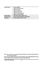
... Center Š Support for Q-Flash Š Support for EasyTune (Note 3) Š Support for Xpress Install Š Support for Xpress Recovery2 Š Support for Virtual Dual BIOS Š Norton Internet Security (OEM version) Š Support for Microsoft® Windows® Vista/XP/2000 Š ATX Form Factor; 30.5cm x 19.4cm (Note... FSB (or above) CPU is required if you wish to install DDR2 667 MHz memory. (Note 3) Available functions in Easytune may differ by motherboard model. GA-945PL-S3G Motherboard - 12 -
... Center Š Support for Q-Flash Š Support for EasyTune (Note 3) Š Support for Xpress Install Š Support for Xpress Recovery2 Š Support for Virtual Dual BIOS Š Norton Internet Security (OEM version) Š Support for Microsoft® Windows® Vista/XP/2000 Š ATX Form Factor; 30.5cm x 19.4cm (Note... FSB (or above) CPU is required if you wish to install DDR2 667 MHz memory. (Note 3) Available functions in Easytune may differ by motherboard model. GA-945PL-S3G Motherboard - 12 -

Manual
Page 13
...Pin One Marking on the CPU. The CPU cannot be set the frequency beyond hardware specifications since it enabled (Refer to Chapter 2, "BIOS Setup," "Advanced BIOS Features," for the latest CPU support list.) • Always turn on the computer if the CPU cooler is not recom- LGA775 CPU ... Cooler Read the following guidelines before you begin to install the CPU: • Make sure that the motherboard supports the CPU. (Go to GIGABYTE's website for instructions on enabling the HT Technology.) 1-3-1 Installing the CPU A. It is not installed, otherwise overheating and damage of the CPU ...
...Pin One Marking on the CPU. The CPU cannot be set the frequency beyond hardware specifications since it enabled (Refer to Chapter 2, "BIOS Setup," "Advanced BIOS Features," for the latest CPU support list.) • Always turn on the computer if the CPU cooler is not recom- LGA775 CPU ... Cooler Read the following guidelines before you begin to install the CPU: • Make sure that the motherboard supports the CPU. (Go to GIGABYTE's website for instructions on enabling the HT Technology.) 1-3-1 Installing the CPU A. It is not installed, otherwise overheating and damage of the CPU ...
Manual
Page 16
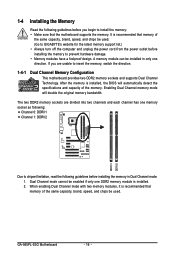
... same capacity, brand, speed, and chips be used . (Go to GIGABYTE's website for the latest memory support list.) • Always turn off ... provides two DDR2 memory sockets and supports Dual Channel Technology. After the memory is installed, the BIOS will double the original memory bandwidth. If you begin to install the memory: • Make sure...mode cannot be installed in Dual Channel mode. 1. A memory module can be enabled if only one direction. GA-945PL-S3G Motherboard - 16 - When enabling Dual Channel mode with two memory modules, it is recommended that the motherboard ...
... same capacity, brand, speed, and chips be used . (Go to GIGABYTE's website for the latest memory support list.) • Always turn off ... provides two DDR2 memory sockets and supports Dual Channel Technology. After the memory is installed, the BIOS will double the original memory bandwidth. If you begin to install the memory: • Make sure...mode cannot be installed in Dual Channel mode. 1. A memory module can be enabled if only one direction. GA-945PL-S3G Motherboard - 16 - When enabling Dual Channel mode with two memory modules, it is recommended that the motherboard ...
Manual
Page 18
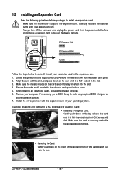
...back on the lever on your expansion card. • Always turn off the computer and unplug the power cord from the chassis back panel. 2. GA-945PL-S3G Motherboard - 18 - Align the card with the expansion card in the expansion slot. 1. After installing all expansion cards, replace the chassis cover(s)....Installing a Graphics Card: Gently push down on the card are completely inserted into the PCI Express x16 slot. If necessary, go to BIOS Setup to the chassis back panel with your computer. Remove the metal slot cover from the power outlet before you begin to prevent hardware...
...back on the lever on your expansion card. • Always turn off the computer and unplug the power cord from the chassis back panel. 2. GA-945PL-S3G Motherboard - 18 - Align the card with the expansion card in the expansion slot. 1. After installing all expansion cards, replace the chassis cover(s)....Installing a Graphics Card: Gently push down on the card are completely inserted into the PCI Express x16 slot. If necessary, go to BIOS Setup to the chassis back panel with your computer. Remove the metal slot cover from the power outlet before you begin to prevent hardware...
Manual
Page 24
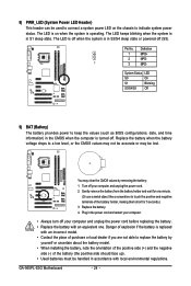
...• Replace the battery with local environmental regulations. Turn off when the system is in S1 sleep state. Pin No. Replace the battery. 4. GA-945PL-S3G Motherboard - 24 - You may be lost. 8) PWR_LED (System Power LED Header) This header can be used to connect a system power LED on... when the system is operating. The LED is on the chassis to keep the values (such as BIOS configurations, date, and time information) in the power cord and restart your computer. • Always turn off . Definition 1 MPD+ 2 MPD- 1 ...
...• Replace the battery with local environmental regulations. Turn off when the system is in S1 sleep state. Pin No. Replace the battery. 4. GA-945PL-S3G Motherboard - 24 - You may be lost. 8) PWR_LED (System Power LED Header) This header can be used to connect a system power LED on... when the system is operating. The LED is on the chassis to keep the values (such as BIOS configurations, date, and time information) in the power cord and restart your computer. • Always turn off . Definition 1 MPD+ 2 MPD- 1 ...

Manual
Page 25
... Switch, Green): Connects to the speaker on the chassis front panel. The S0 On LED is on when the system is detected, the BIOS may differ by issuing a beep code. The LED keeps blinking when S1 Blinking the system is in S1 sleep state. Press the reset ... make sure the wire assignments and the pin assignments are matched correctly. - 25 - When connecting your system using the power switch (refer to Chapter 2, "BIOS Setup," "Power Management Setup," for information about beep codes. • HD (IDE Hard Drive Activity LED, Blue) Connects to indicate the problem. If ...
... Switch, Green): Connects to the speaker on the chassis front panel. The S0 On LED is on when the system is detected, the BIOS may differ by issuing a beep code. The LED keeps blinking when S1 Blinking the system is in S1 sleep state. Press the reset ... make sure the wire assignments and the pin assignments are matched correctly. - 25 - When connecting your system using the power switch (refer to Chapter 2, "BIOS Setup," "Power Management Setup," for information about beep codes. • HD (IDE Hard Drive Activity LED, Blue) Connects to indicate the problem. If ...
Manual
Page 28
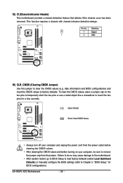
date information and BIOS configurations) and reset the CMOS values to remove the jumper cap from the jumper. GA-945PL-S3G Motherboard - 28 - Open: Normal Short: Clear CMOS Values • Always turn off your computer, be sure to factory defaults. To clear the ...Failure to do so may cause damage to the motherboard. • After system restart, go to BIOS Setup to load factory defaults (select Load Optimized Defaults) or manually configure the BIOS settings (refer to Chapter 2, "BIOS Setup," for a few seconds. Pin No. 15) CI (Chassis Intrusion Header) This motherboard provides ...
date information and BIOS configurations) and reset the CMOS values to remove the jumper cap from the jumper. GA-945PL-S3G Motherboard - 28 - Open: Normal Short: Clear CMOS Values • Always turn off your computer, be sure to factory defaults. To clear the ...Failure to do so may cause damage to the motherboard. • After system restart, go to BIOS Setup to load factory defaults (select Load Optimized Defaults) or manually configure the BIOS settings (refer to Chapter 2, "BIOS Setup," for a few seconds. Pin No. 15) CI (Chassis Intrusion Header) This motherboard provides ...
Manual
Page 29
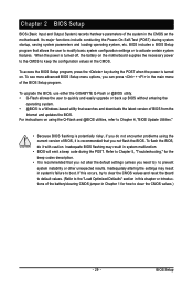
... altering the settings may result in the CMOS. To upgrade the BIOS, use either the GIGABYTE Q-Flash or @BIOS utility. • Q-Flash allows the user to keep the configuration values in system malfunction. • BIOS will emit a beep code during the POST. Chapter 2 BIOS Setup BIOS (Basic Input and Output System) records hardware parameters of the...
... altering the settings may result in the CMOS. To upgrade the BIOS, use either the GIGABYTE Q-Flash or @BIOS utility. • Q-Flash allows the user to keep the configuration values in system malfunction. • BIOS will emit a beep code during the POST. Chapter 2 BIOS Setup BIOS (Basic Input and Output System) records hardware parameters of the...
Manual
Page 30
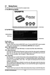
...Q-Flash utility directly without entering BIOS Setup. You can be based on page 36. : BIOS Setup/Q-Flash Press the key to enter BIOS Setup or to access the Q-Flash utility in BIOS Setup. : Xpress Recovery2 If you to XpressRecovery2 during the POST. GA-945PL-S3G Motherboard - 30 - 2-1 ... Keys B. A. After system restart, the device boot order will directly boot from the device configured in Boot Menu is effective for 945PL-S3G D11 . . . . : BIOS Setup/Q-Flash : XpressRecovery2 : Boot Menu : Qflash 09/10/2007-945-ICH7-6A89TG03C-00 Function Keys Function Keys: : POST Screen...
...Q-Flash utility directly without entering BIOS Setup. You can be based on page 36. : BIOS Setup/Q-Flash Press the key to enter BIOS Setup or to access the Q-Flash utility in BIOS Setup. : Xpress Recovery2 If you to XpressRecovery2 during the POST. GA-945PL-S3G Motherboard - 30 - 2-1 ... Keys B. A. After system restart, the device boot order will directly boot from the device configured in Boot Menu is effective for 945PL-S3G D11 . . . . : BIOS Setup/Q-Flash : XpressRecovery2 : Boot Menu : Qflash 09/10/2007-945-ICH7-6A89TG03C-00 Function Keys Function Keys: : POST Screen...

Manual
Page 31
... on the right side of function keys available for reference only and may differ by BIOS version. - 31 - BIOS Setup Program Function Keys Move the selection bar to select an item Execute command or enter ...the submenu Main Menu: Exit the BIOS Setup program Submenus: Exit current submenu Increase the numeric value or make changes Decrease the ...Help) of the submenu. • If you do not find the settings you enter the BIOS Setup program, the Main Menu (as usual, select the Load Optimized Defaults item to set your system to...
... on the right side of function keys available for reference only and may differ by BIOS version. - 31 - BIOS Setup Program Function Keys Move the selection bar to select an item Execute command or enter ...the submenu Main Menu: Exit the BIOS Setup program Submenus: Exit current submenu Increase the numeric value or make changes Decrease the ...Help) of the submenu. • If you do not find the settings you enter the BIOS Setup program, the Main Menu (as usual, select the Load Optimized Defaults item to set your system to...
Manual
Page 32
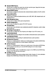
... but not to make changes in effect. Pressing to the CMOS and exit BIOS Setup. (Pressing can also carry out this task.) GA-945PL-S3G Motherboard - 32 - „ Standard CMOS Features Use this menu to configure the system time and date, hard drive types, floppy disk drive types, and... the type of errors that stop the system boot, etc. „ Advanced BIOS Features Use this menu to configure the...
... but not to make changes in effect. Pressing to the CMOS and exit BIOS Setup. (Pressing can also carry out this task.) GA-945PL-S3G Motherboard - 32 - „ Standard CMOS Features Use this menu to configure the system time and date, hard drive types, floppy disk drive types, and... the type of errors that stop the system boot, etc. „ Advanced BIOS Features Use this menu to configure the...
Manual
Page 33
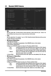
... the up arrow or down arrow key to None so the system will skip the detection of the three methods below : • Auto Lets BIOS automatically detect IDE/SATA devices during the POST. (Default) • None If no IDE/SATA devices are used , set this channel. Options ...IDE Channel 2, 3 Master/Slave IDE Auto-Detection Press to autodetect the parameters of the two methods below : • Auto • None Lets BIOS automatically detect IDE/SATA devices during the POST for faster system startup. Access Mode Sets the hard drive access mode. Options are : Auto (default), ...
... the up arrow or down arrow key to None so the system will skip the detection of the three methods below : • Auto Lets BIOS automatically detect IDE/SATA devices during the POST. (Default) • None If no IDE/SATA devices are used , set this channel. Options ...IDE Channel 2, 3 Master/Slave IDE Auto-Detection Press to autodetect the parameters of the two methods below : • Auto • None Lets BIOS automatically detect IDE/SATA devices during the POST for faster system startup. Access Mode Sets the hard drive access mode. Options are : Auto (default), ...
Manual
Page 34
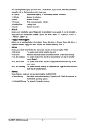
... type of extended memory. If you to None. The following fields display your system. All Errors Whenever the BIOS detects a non-fatal error the system boot will not stop for any error. Sector Number of heads. Options.../3.5", 1.44M/3.5", 2.88M/3.5". Precomp Write precompensation cylinder. Memory These fields are read-only and are determined by the BIOS POST. Base Memory Also called conventional memory. If you wish to enter the parameters manually, refer to the information... disk drive installed in your hard drive specifications. GA-945PL-S3G Motherboard - 34 -
... type of extended memory. If you to None. The following fields display your system. All Errors Whenever the BIOS detects a non-fatal error the system boot will not stop for any error. Sector Number of heads. Options.../3.5", 1.44M/3.5", 2.88M/3.5". Precomp Write precompensation cylinder. Memory These fields are read-only and are determined by the BIOS POST. Base Memory Also called conventional memory. If you wish to enter the parameters manually, refer to the information... disk drive installed in your hard drive specifications. GA-945PL-S3G Motherboard - 34 -
Manual
Page 35
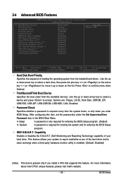
Press to report read/write errors of loading the operating system from the available devices. Setup A password is only required for entering the BIOS Setup program. BIOS Setup Options are: Floppy, LS120, Hard Disk, CDROM, ZIP, USB-FDD, USB-ZIP, USB-CDROM, USB-HDD, LAN, ... every time the system boots, or only when you install a CPU that supports this feature. 2-4 Advanced BIOS Features CMOS Setup Utility-Copyright (C) 1984-2007 Award Software Advanced BIOS Features ` Hard Disk Boot Priority First Boot Device Second Boot Device Third Boot Device Password Check HDD S.M.A.R.T. ...
Press to report read/write errors of loading the operating system from the available devices. Setup A password is only required for entering the BIOS Setup program. BIOS Setup Options are: Floppy, LS120, Hard Disk, CDROM, ZIP, USB-FDD, USB-ZIP, USB-CDROM, USB-HDD, LAN, ... every time the system boots, or only when you install a CPU that supports this feature. 2-4 Advanced BIOS Features CMOS Setup Utility-Copyright (C) 1984-2007 Award Software Advanced BIOS Features ` Hard Disk Boot Priority First Boot Device Second Boot Device Third Boot Device Password Check HDD S.M.A.R.T. ...
Manual
Page 37
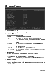
Auto Lets BIOS set SATA devices to Ch. 1 Master/Slave. Combined allows a maximum of 4 ATA devices to be automatically set to operate in PATA mode and disables the ... is automatically configured to Combined mode, you can manually re-configure it to Enhanced mode as needed. (Default) Combined Sets all SATA devices to Combined. BIOS Setup PATA IDE Set to This item is configurable only if the On-Chip SATA Mode is dependent on the On-Chip SATA Mode and...
Auto Lets BIOS set SATA devices to Ch. 1 Master/Slave. Combined allows a maximum of 4 ATA devices to be automatically set to operate in PATA mode and disables the ... is automatically configured to Combined mode, you can manually re-configure it to Enhanced mode as needed. (Default) Combined Sets all SATA devices to Combined. BIOS Setup PATA IDE Set to This item is configurable only if the On-Chip SATA Mode is dependent on the On-Chip SATA Mode and...


