Manual
Page 1
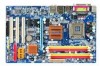
GA-945P-DS3/S3 Intel® CoreTM 2 Extreme dual-core / CoreTM 2 Duo / Intel® Pentium® D / Pentium® 4 / Celeron® D LGA775 Processor Motherboard User's Manual Rev. 3301 12ME-945PDS3-3301R * The WEEE marking on the product indicates this product must not be disposed of with user's other household waste and must be handed over to a designated collection point for the recycling of waste electrical and electronic equipment!! * The WEEE marking applies only in European Union's member states.
GA-945P-DS3/S3 Intel® CoreTM 2 Extreme dual-core / CoreTM 2 Duo / Intel® Pentium® D / Pentium® 4 / Celeron® D LGA775 Processor Motherboard User's Manual Rev. 3301 12ME-945PDS3-3301R * The WEEE marking on the product indicates this product must not be disposed of with user's other household waste and must be handed over to a designated collection point for the recycling of waste electrical and electronic equipment!! * The WEEE marking applies only in European Union's member states.
Manual
Page 2
Motherboard GA-945P-DS3/GA-945P-S3 Oct. 27, 2006 Motherboard GA-945P-DS3/ GA-945P-S3 Oct. 27, 2006
Motherboard GA-945P-DS3/GA-945P-S3 Oct. 27, 2006 Motherboard GA-945P-DS3/ GA-945P-S3 Oct. 27, 2006
Manual
Page 4
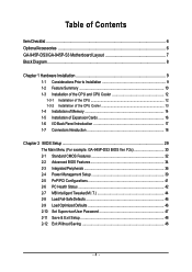
Table of Contents ItemChecklist ...6 OptionalAccessories ...6 GA-945P-DS3/GA-945P-S3 Motherboard Layout 7 Block Diagram ...8 Chapter 1 Hardware Installation 9 1-1 Considerations Prior to Installation 9 1-2 Feature Summary 10 1-3 Installation of the CPU and CPU Cooler 12 1-3-1 Installation of the ... Configurations 41 2-6 PC Health Status 42 2-7 MB Intelligent Tweaker(M.I /O Back Panel Introduction 17 1-7 Connectors Introduction 18 Chapter 2 BIOS Setup 29 The Main Menu (For example: GA-945P-DS3 BIOS Ver.
Table of Contents ItemChecklist ...6 OptionalAccessories ...6 GA-945P-DS3/GA-945P-S3 Motherboard Layout 7 Block Diagram ...8 Chapter 1 Hardware Installation 9 1-1 Considerations Prior to Installation 9 1-2 Feature Summary 10 1-3 Installation of the CPU and CPU Cooler 12 1-3-1 Installation of the ... Configurations 41 2-6 PC Health Status 42 2-7 MB Intelligent Tweaker(M.I /O Back Panel Introduction 17 1-7 Connectors Introduction 18 Chapter 2 BIOS Setup 29 The Main Menu (For example: GA-945P-DS3 BIOS Ver.
Manual
Page 7
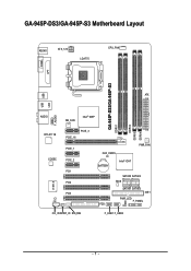
GA-945P-DS3/GA-945P-S3 Motherboard Layout KB_MS ATX_12V LGA775 CPU_FAN COMA LPT GA-945P-DS3/GA-945P-S3 DDRII1 DDRII2 DDRII3 DDRII4 USB USB LAN ATX F_AUDIO AUDIO NB_FAN Intel® 945P RTL8111B CODEC CI IT8718 PCIE_16 PCIE_3 PCIE_1 PCIE_2 PCI1 PCI2 PCI3 CD_IN SPDIF_IO SYS_FAN CLR_CMOS BATTERY Intel® ICH7 PWR_FAN SATAII0 SATAII2 BIOS SATAII1 SATAII3 IDE1 PWR_LED F_PANEL FDD F_USB1 F_USB2 - 7 -
GA-945P-DS3/GA-945P-S3 Motherboard Layout KB_MS ATX_12V LGA775 CPU_FAN COMA LPT GA-945P-DS3/GA-945P-S3 DDRII1 DDRII2 DDRII3 DDRII4 USB USB LAN ATX F_AUDIO AUDIO NB_FAN Intel® 945P RTL8111B CODEC CI IT8718 PCIE_16 PCIE_3 PCIE_1 PCIE_2 PCI1 PCI2 PCI3 CD_IN SPDIF_IO SYS_FAN CLR_CMOS BATTERY Intel® ICH7 PWR_FAN SATAII0 SATAII2 BIOS SATAII1 SATAII3 IDE1 PWR_LED F_PANEL FDD F_USB1 F_USB2 - 7 -
Manual
Page 10
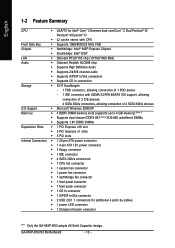
GA-945P-DS3/S3 Motherboard - 10 - English 1-2 Feature Summary CPU Š LGA775 for Intel® CoreTM 2 Extreme dual-core/CoreTM 2 Duo/Pentium® D/ Pentium® 4/Celeron® D Š L2 cache varies with CPU Front Side Bus Š Supports 1066/800/533 MHz FSB Chipset Š Northbridge: Intel® 945P Express Chipset Š Southbridge: Intel&#...Š 1 S/PDIF In/Out connector Š 2 USB 2.0/1.1 connectors for additional 4 ports by cables Š 1 power LED connector Š 1 Chassis Intrusion connector "*" Only the GA-945P-DS3 adopts All-Solid Capacitor design.
GA-945P-DS3/S3 Motherboard - 10 - English 1-2 Feature Summary CPU Š LGA775 for Intel® CoreTM 2 Extreme dual-core/CoreTM 2 Duo/Pentium® D/ Pentium® 4/Celeron® D Š L2 cache varies with CPU Front Side Bus Š Supports 1066/800/533 MHz FSB Chipset Š Northbridge: Intel® 945P Express Chipset Š Southbridge: Intel&#...Š 1 S/PDIF In/Out connector Š 2 USB 2.0/1.1 connectors for additional 4 ports by cables Š 1 power LED connector Š 1 Chassis Intrusion connector "*" Only the GA-945P-DS3 adopts All-Solid Capacitor design.
Manual
Page 12
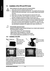
... - Fig. 4 Once the CPU is installed on the CPU socket to set beyond the proper specifications, please do so according to the CPU during installation.) GA-945P-DS3/S3 Motherboard - 12 - If you install the CPU in the wrong direction, the CPU will not insert properly. Please add an even layer of the CPU...
... - Fig. 4 Once the CPU is installed on the CPU socket to set beyond the proper specifications, please do so according to the CPU during installation.) GA-945P-DS3/S3 Motherboard - 12 - If you install the CPU in the wrong direction, the CPU will not insert properly. Please add an even layer of the CPU...
Manual
Page 14
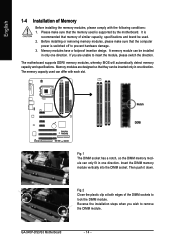
... can be used is supported by the motherboard. Reverse the installation steps when you are designed so that they can differ with the following conditions: 1. GA-945P-DS3/S3 Motherboard - 14 - A memory module can only fit in only one direction. Memory modules are unable to prevent hardware damage. 3. Then push it down. If you...
... can be used is supported by the motherboard. Reverse the installation steps when you are designed so that they can differ with the following conditions: 1. GA-945P-DS3/S3 Motherboard - 14 - A memory module can only fit in only one direction. Memory modules are unable to prevent hardware damage. 3. Then push it down. If you...
Manual
Page 15
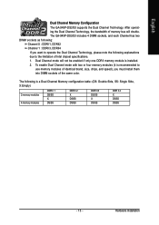
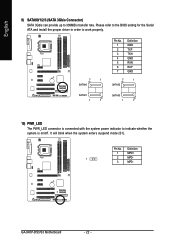
... identical brand, size, chips, and speed), you must install them into DIMM sockets of the same color. Hardware Installation Dual Channel mode will double. The GA-945P-DS3/S3 includes 4 DIMM sockets, and each Channel has two DIMM sockets as following: Channel 0 : DDRII1, DDRII2 Channel 1 : DDRII3, DDRII4 If you want to ... X DS/SS DS/SS DDR II 3 DS/SS X DS/SS DDR II 4 X DS/SS DS/SS - 15 - English Dual Channel Memory Configuration The GA-945P-DS3/S3 supports the Dual Channel Technology. After operating the Dual Channel Technology, the bandwidth of Intel chipset specifications. 1.
... identical brand, size, chips, and speed), you must install them into DIMM sockets of the same color. Hardware Installation Dual Channel mode will double. The GA-945P-DS3/S3 includes 4 DIMM sockets, and each Channel has two DIMM sockets as following: Channel 0 : DDRII1, DDRII2 Channel 1 : DDRII3, DDRII4 If you want to ... X DS/SS DS/SS DDR II 3 DS/SS X DS/SS DDR II 4 X DS/SS DS/SS - 15 - English Dual Channel Memory Configuration The GA-945P-DS3/S3 supports the Dual Channel Technology. After operating the Dual Channel Technology, the bandwidth of Intel chipset specifications. 1.
Manual
Page 16
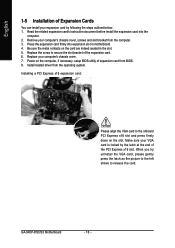
... latch as the picture to the left shows to release the card. Make sure your VGA card is locked by following the steps outlined below: 1. GA-945P-DS3/S3 Motherboard - 16 - Read the related expansion card's instruction document before install the expansion card into expansion slot in the slot. 5. Power on the slot. Install...
... latch as the picture to the left shows to release the card. Make sure your VGA card is locked by following the steps outlined below: 1. GA-945P-DS3/S3 Motherboard - 16 - Read the related expansion card's instruction document before install the expansion card into expansion slot in the slot. 5. Power on the slot. Install...
Manual
Page 18
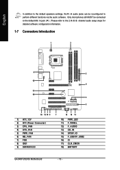
... 7) FDD 8) IDE1 9) SATAII0/1/2/3 7 15 10 11 10) PWR_LED 11) F_PANEL 12) F_AUDIO 13) CD_IN 14) SPDIF_IO 15) F_USB1/F_USB2 16) CI 17) CLR_CMOS 18) BATTERY GA-945P-DS3/S3 Motherboard - 18 - Only microphones still MUST be reconfigured to perform different functions via the audio software. English In addition to the default speakers settings, the...
... 7) FDD 8) IDE1 9) SATAII0/1/2/3 7 15 10 11 10) PWR_LED 11) F_PANEL 12) F_AUDIO 13) CD_IN 14) SPDIF_IO 15) F_USB1/F_USB2 16) CI 17) CLR_CMOS 18) BATTERY GA-945P-DS3/S3 Motherboard - 18 - Only microphones still MUST be reconfigured to perform different functions via the audio software. English In addition to the default speakers settings, the...
Manual
Page 20
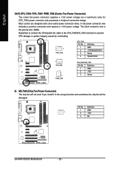
... caused by overheating. 1 CPU_FAN CPU_FAN: Pin No. 1 2 3 4 Definition GND +12V/Speed Control Sense Speed Control 1 SYS_FAN 1 PWR_FAN SYS_FAN/PWR_FAN: Pin No. Definition 1 GND 1 2 +12V 3 NC GA-945P-DS3/S3 Motherboard - 20 - Pin No. A red power connector wire indicates a positive connection and requires a +12V power voltage. The black connector wire is the ground wire (GND...
... caused by overheating. 1 CPU_FAN CPU_FAN: Pin No. 1 2 3 4 Definition GND +12V/Speed Control Sense Speed Control 1 SYS_FAN 1 PWR_FAN SYS_FAN/PWR_FAN: Pin No. Definition 1 GND 1 2 +12V 3 NC GA-945P-DS3/S3 Motherboard - 20 - Pin No. A red power connector wire indicates a positive connection and requires a +12V power voltage. The black connector wire is the ground wire (GND...
Manual
Page 22
... rate. Pin No. Definition 1 MPD+ 1 2 MPD- 3 MPD- English 9) SATAII0/1/2/3 (SATA 3Gb/s Connector) SATA 3Gb/s can provide up to indicate whether the system is on/off. GA-945P-DS3/S3 Motherboard - 22 -
... rate. Pin No. Definition 1 MPD+ 1 2 MPD- 3 MPD- English 9) SATAII0/1/2/3 (SATA 3Gb/s Connector) SATA 3Gb/s can provide up to indicate whether the system is on/off. GA-945P-DS3/S3 Motherboard - 22 -
Manual
Page 24
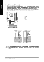
... assignments carefully while you wish to use the front audio function, connect the front panel audio module to this connector, please refer to this connector. GA-945P-DS3/S3 Motherboard - 24 -
... assignments carefully while you wish to use the front audio function, connect the front panel audio module to this connector, please refer to this connector. GA-945P-DS3/S3 Motherboard - 24 -
Manual
Page 26
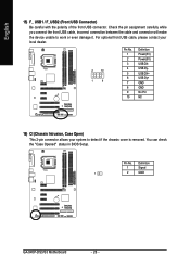
..." status in BIOS Setup. English 15) F_ USB1 / F_USB2 (Front USB Connector) Be careful with the polarity of the front USB connector. Definition 1 Signal 1 2 GND GA-945P-DS3/S3 Motherboard - 26 - Pin No. For optional front USB cable, please contact your local dealer. 2 10 1 9 Pin No. 1 2 3 4 5 6 7 8 9 10 Definition Power(5V) Power(5V) USB DXUSB...
..." status in BIOS Setup. English 15) F_ USB1 / F_USB2 (Front USB Connector) Be careful with the polarity of the front USB connector. Definition 1 Signal 1 2 GND GA-945P-DS3/S3 Motherboard - 26 - Pin No. For optional front USB cable, please contact your local dealer. 2 10 1 9 Pin No. 1 2 3 4 5 6 7 8 9 10 Definition Power(5V) Power(5V) USB DXUSB...

Manual
Page 28
English GA-945P-DS3/S3 Motherboard - 28 -
English GA-945P-DS3/S3 Motherboard - 28 -

Manual
Page 30
F2c) Once you want, press "Ctrl+F1" to access advanced options. 2. GA-945P-DS3/S3 Motherboard - 30 - Use arrow keys to select among the items and press to accept or enter the sub-menu. CMOS Setup Utility-Copyright (C) 1984-2007 ... differ from the exact settings for stability. 3. This action makes the system reset to the default settings for your motherboard. The Main Menu (For example: GA-945P-DS3 BIOS Ver. The BIOS Setup menus described in the BIOS Setup when somehow the system is not stable as figure below) will appear on page...
F2c) Once you want, press "Ctrl+F1" to access advanced options. 2. GA-945P-DS3/S3 Motherboard - 30 - Use arrow keys to select among the items and press to accept or enter the sub-menu. CMOS Setup Utility-Copyright (C) 1984-2007 ... differ from the exact settings for stability. 3. This action makes the system reset to the default settings for your motherboard. The Main Menu (For example: GA-945P-DS3 BIOS Ver. The BIOS Setup menus described in the BIOS Setup when somehow the system is not stable as figure below) will appear on page...
Manual
Page 32
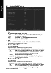
.../Slave IDE/SATA Device Setup. The four options are used and the system will skip the automatic detection step and allow for the hard drive. GA-945P-DS3/S3 Motherboard - 32 - Through Dec The day, from 1 to set the access mode for faster system start up . The time is 13:0:0. You can use one...
.../Slave IDE/SATA Device Setup. The four options are used and the system will skip the automatic detection step and allow for the hard drive. GA-945P-DS3/S3 Motherboard - 32 - Through Dec The day, from 1 to set the access mode for faster system start up . The time is 13:0:0. You can use one...
Manual
Page 34
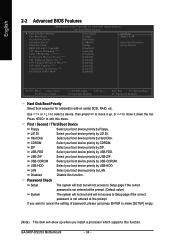
... Utility-Copyright (C) 1984-2007 Award Software Advanced BIOS Features ` Hard Disk Boot Priority First Boot Device Second Boot Device Third Boot Device Password Check HDD S.M.A.R.T. GA-945P-DS3/S3 Motherboard - 34 - Use < > or < > to select a device, then press to exit this function. USB-ZIP Select your boot device priority by USB-ZIP. USB-CDROM...
... Utility-Copyright (C) 1984-2007 Award Software Advanced BIOS Features ` Hard Disk Boot Priority First Boot Device Second Boot Device Third Boot Device Password Check HDD S.M.A.R.T. GA-945P-DS3/S3 Motherboard - 34 - Use < > or < > to select a device, then press to exit this function. USB-ZIP Select your boot device priority by USB-ZIP. USB-CDROM...
Manual
Page 36
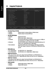
... to Ch. 0 Master/Slave. (Default value) SATA Port 0/2 Set to Ch. 0 Master/Slave. USB Controller Enabled Enable USB Controller. (Default value) Disabled Disable USB Controller. GA-945P-DS3/S3 Motherboard - 36 - Support a maximum of 4 SATA devices. If PATA IDE were set to This value will be simulated to PATA mode. PATA IDE Set to...
... to Ch. 0 Master/Slave. (Default value) SATA Port 0/2 Set to Ch. 0 Master/Slave. USB Controller Enabled Enable USB Controller. (Default value) Disabled Disable USB Controller. GA-945P-DS3/S3 Motherboard - 36 - Support a maximum of 4 SATA devices. If PATA IDE were set to This value will be simulated to PATA mode. PATA IDE Set to...
Manual
Page 38
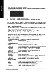
... Enable onboard LPT port and address is 278/IRQ5. 3BC/IRQ7 Enable onboard LPT port and address is 2E8/IRQ3. Disabled Disable onboard Serial port 1. GA-945P-DS3/S3 Motherboard - 38 - ECP+EPP Using Parallel port as Enhanced Parallel Port. Note: The Gigabit hub will be the approximate distance to the fault or short...
... Enable onboard LPT port and address is 278/IRQ5. 3BC/IRQ7 Enable onboard LPT port and address is 2E8/IRQ3. Disabled Disable onboard Serial port 1. GA-945P-DS3/S3 Motherboard - 38 - ECP+EPP Using Parallel port as Enhanced Parallel Port. Note: The Gigabit hub will be the approximate distance to the fault or short...

