Manual
Page 1
GA-945GZM-S2 Intel® CoreTM 2 Extreme dual-core / CoreTM 2 Duo / Intel® Pentium® D / Pentium® 4 / Celeron® D LGA775 Processor Motherboard User's Manual Rev. 6601 12ME-945GZMS2-6601R * The WEEE marking on the product indicates this product must not be disposed of with user's other household waste and must be handed over to a designated collection point for the recycling of waste electrical and electronic equipment!! * The WEEE marking applies only in European Union's member states.
GA-945GZM-S2 Intel® CoreTM 2 Extreme dual-core / CoreTM 2 Duo / Intel® Pentium® D / Pentium® 4 / Celeron® D LGA775 Processor Motherboard User's Manual Rev. 6601 12ME-945GZMS2-6601R * The WEEE marking on the product indicates this product must not be disposed of with user's other household waste and must be handed over to a designated collection point for the recycling of waste electrical and electronic equipment!! * The WEEE marking applies only in European Union's member states.
Manual
Page 2
Motherboard GA-945GZM-S2 Jan. 12, 2007 Motherboard GA-945GZM-S2 Jan. 12, 2007
Motherboard GA-945GZM-S2 Jan. 12, 2007 Motherboard GA-945GZM-S2 Jan. 12, 2007

Manual
Page 4
Table of Contents ItemChecklist ...6 OptionalAccessories ...6 GA-945GZM-S2 Motherboard Layout 7 Block Diagram ...8 Chapter 1 Hardware Installation 9 1-1 Considerations Prior to Installation 9 1-2 Feature Summary 10 1-3 Installation of the CPU and CPU Cooler 12 1-3-1 Installation of the CPU ...
Table of Contents ItemChecklist ...6 OptionalAccessories ...6 GA-945GZM-S2 Motherboard Layout 7 Block Diagram ...8 Chapter 1 Hardware Installation 9 1-1 Considerations Prior to Installation 9 1-2 Feature Summary 10 1-3 Installation of the CPU and CPU Cooler 12 1-3-1 Installation of the CPU ...

Manual
Page 7
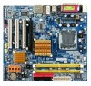
GA-945GZM-S2 Motherboard Layout KB_MS ATX_12V LGA775 CPU_FAN GA-945GZM-S2 ATX IT8718 COMA VGA LPT R_USB USB_LAN SYS _FAN AUDIO F_AUDIO RTL8110SC Intel® 945 PCIE_16 PCI1 DDRII1 DDRII2 IDE FDD SATAII2 SATAII3 CODEC CD_IN SPDIF_IO COMB PCI2 Intel® ICH7 PCI3 BIOS SATAII0 SATAII1 F_USB1 F_USB2 PWR_LED BATTERY CI CLR_CMOS F_PANEL - 7 -
GA-945GZM-S2 Motherboard Layout KB_MS ATX_12V LGA775 CPU_FAN GA-945GZM-S2 ATX IT8718 COMA VGA LPT R_USB USB_LAN SYS _FAN AUDIO F_AUDIO RTL8110SC Intel® 945 PCIE_16 PCI1 DDRII1 DDRII2 IDE FDD SATAII2 SATAII3 CODEC CD_IN SPDIF_IO COMB PCI2 Intel® ICH7 PCI3 BIOS SATAII0 SATAII1 F_USB1 F_USB2 PWR_LED BATTERY CI CLR_CMOS F_PANEL - 7 -
Manual
Page 9
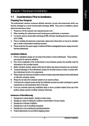
... to use of the product, please consult a certified computer technician. Hardware Installation Please do not remove the stickers on the motherboard or within a electrostatic shielding container. 5. Damage due to be an unofficial Gigabyte product. - 9 - Product determined to improper installation. 4. Prior to installing the electronic components, please have a problem related to the use...
... to use of the product, please consult a certified computer technician. Hardware Installation Please do not remove the stickers on the motherboard or within a electrostatic shielding container. 5. Damage due to be an unofficial Gigabyte product. - 9 - Product determined to improper installation. 4. Prior to installing the electronic components, please have a problem related to the use...
Manual
Page 10
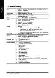
... Š 1 S/PDIF In/Out connector Š 2 USB 2.0/1.1 connectors for additional 4 USB 2.0/1.1 ports by cables Š 1 COMB connector Š 1 power LED connector Š 1 Chassis Intrusion connector GA-945GZM-S2 Motherboard - 10 -
... Š 1 S/PDIF In/Out connector Š 2 USB 2.0/1.1 connectors for additional 4 USB 2.0/1.1 ports by cables Š 1 COMB connector Š 1 power LED connector Š 1 Chassis Intrusion connector GA-945GZM-S2 Motherboard - 10 -
Manual
Page 11
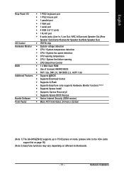
... BIOS Rescue Bundle Software Š Norton Internet Security (OEM version) Form Factor Š Micro ATX form factor; 24.4cm x 22.0cm (Note 1) The GA-945GZM-S2 supports up to PCI Express x4 mode. (please refer to the VGA cards support list on page 16) (Note 2) EasyTune functions may vary depending on different motherboards. - 11 -
... BIOS Rescue Bundle Software Š Norton Internet Security (OEM version) Form Factor Š Micro ATX form factor; 24.4cm x 22.0cm (Note 1) The GA-945GZM-S2 supports up to PCI Express x4 mode. (please refer to the VGA cards support list on page 16) (Note 2) EasyTune functions may vary depending on different motherboards. - 11 -

Manual
Page 12
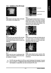
.... Fig. 4 Once the CPU is not recommended that might cause damage to the upright position. OS: An operation system that the motherboard supports the CPU. 2. Please set the frequency beyond hardware specifications since it enabled - If you install the CPU in the wrong direction...CPU. 3. English 1-3 Installation of the CPU. Please make sure the heatsink is installed on the CPU socket to the CPU during installation.) GA-945GZM-S2 Motherboard - 12 - Please take note of the one indented corner of the CPU and CPU Cooler Before installing the CPU, please comply with ...
.... Fig. 4 Once the CPU is not recommended that might cause damage to the upright position. OS: An operation system that the motherboard supports the CPU. 2. Please set the frequency beyond hardware specifications since it enabled - If you install the CPU in the wrong direction...CPU. 3. English 1-3 Installation of the CPU. Please make sure the heatsink is installed on the CPU socket to the CPU during installation.) GA-945GZM-S2 Motherboard - 12 - Please take note of the one indented corner of the CPU and CPU Cooler Before installing the CPU, please comply with ...
Manual
Page 13
If the push pin is inserted as a result of hardening of motherboard after installing. The CPU cooler may adhere to the CPU fan header located on the surface...The top of Female Push Pin Female Push Pin Fig.1 Please apply an even layer of CPU cooler paste on the motherboard. Fig. 6 Finally, please attach the power connector of the CPU cooler to the CPU as the picture, the ...This instruction is only for detailed installation instructions, please refer to the pin hole on the motherboard.Pressing down the push pins diagonally. To prevent such an occurrence, it is complete.
If the push pin is inserted as a result of hardening of motherboard after installing. The CPU cooler may adhere to the CPU fan header located on the surface...The top of Female Push Pin Female Push Pin Fig.1 Please apply an even layer of CPU cooler paste on the motherboard. Fig. 6 Finally, please attach the power connector of the CPU cooler to the CPU as the picture, the ...This instruction is only for detailed installation instructions, please refer to the pin hole on the motherboard.Pressing down the push pins diagonally. To prevent such an occurrence, it is complete.
Manual
Page 14
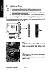
... memory modules, whereby BIOS will automatically detect memory capacity and specifications. The memory capacity used can be inserted only in one direction. GA-945GZM-S2 Motherboard - 14 - Notch DDRII Fig.1 The DIMM socket has a notch, so the DIMM memory module can be used is switched off...Installation of Memory Before installing the memory modules, please comply with each slot. It is recommended that the computer power is supported by the motherboard. Reverse the installation steps when you are designed so that the memory used . 2. A memory module can only fit in only one...
... memory modules, whereby BIOS will automatically detect memory capacity and specifications. The memory capacity used can be inserted only in one direction. GA-945GZM-S2 Motherboard - 14 - Notch DDRII Fig.1 The DIMM socket has a notch, so the DIMM memory module can be used is switched off...Installation of Memory Before installing the memory modules, please comply with each slot. It is recommended that the computer power is supported by the motherboard. Reverse the installation steps when you are designed so that the memory used . 2. A memory module can only fit in only one...

Manual
Page 15
...For example: Installing a PCI Express x16 VGA card: When installing the graphics card, push down on the card are indeed seated in motherboard. 4. Replace the screw to secure the slot bracket of identical brand, size, chips, and speed), you want to use memory modules...8. After operating the Dual Channel Technology, the bandwidth of expansion card from the slot. - 15 - English Dual Channel Memory Configuration The GA-945GZM-S2 supports the Dual Channel Technology. If you must install them into the computer. 2. Read the related expansion card's instruction document before install ...
...For example: Installing a PCI Express x16 VGA card: When installing the graphics card, push down on the card are indeed seated in motherboard. 4. Replace the screw to secure the slot bracket of identical brand, size, chips, and speed), you want to use memory modules...8. After operating the Dual Channel Technology, the bandwidth of expansion card from the slot. - 15 - English Dual Channel Memory Configuration The GA-945GZM-S2 supports the Dual Channel Technology. If you must install them into the computer. 2. Read the related expansion card's instruction document before install ...

Manual
Page 16
... Nvidia ATi Maker Gigabyte Gigabyte Gigabyte Gigabyte Gigabyte Gigabyte Gigabyte Gigabyte Gigabyte Gigabyte Gigabyte Gigabyte Gigabyte Gigabyte Gigabyte Gigabyte Gigabyte Gigabyte Gigabyte Gigabyte Nvidia Nvidia ASUS MSI WinFast Gigabyte Gigabyte Gigabyte Gigabyte Gigabyte Gigabyte Gigabyte Gigabyte Gigabyte Gigabyte Gigabyte Gigabyte Gigabyte Gigabyte Gigabyte Gigabyte ASUS ASUS MSI Model...GV-RX13P256D-RH GV-RX16P256D-RH GV-RX18L256V-B GV-RX18T512V-B AX800XT AX700PRO RX600 XT-TD128 GA-945GZM-S2 Motherboard - 16 - English PCI Express x16 Graphics Card Support List The items below are all...
... Nvidia ATi Maker Gigabyte Gigabyte Gigabyte Gigabyte Gigabyte Gigabyte Gigabyte Gigabyte Gigabyte Gigabyte Gigabyte Gigabyte Gigabyte Gigabyte Gigabyte Gigabyte Gigabyte Gigabyte Gigabyte Gigabyte Nvidia Nvidia ASUS MSI WinFast Gigabyte Gigabyte Gigabyte Gigabyte Gigabyte Gigabyte Gigabyte Gigabyte Gigabyte Gigabyte Gigabyte Gigabyte Gigabyte Gigabyte Gigabyte Gigabyte ASUS ASUS MSI Model...GV-RX13P256D-RH GV-RX16P256D-RH GV-RX18L256V-B GV-RX18T512V-B AX800XT AX700PRO RX600 XT-TD128 GA-945GZM-S2 Motherboard - 16 - English PCI Express x16 Graphics Card Support List The items below are all...
Manual
Page 18
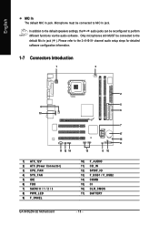
... 6) FDD 7) SATAII 0 / 1 / 2 / 3 8) PWR_LED 9) F_PANEL 2 5 6 7 17 15 9 13 8 16 10) F_AUDIO 11) CD_IN 12) SPDIF_IO 13) F_USB1 / F_USB2 14) COMB 15) CI 16) CLR_CMOS 17) BATTERY GA-945GZM-S2 Motherboard - 18 - Microphone must be connected to MIC In jack. In addition to the default speakers settings, the ~ audio jacks can be reconfigured to the 2-/4-/6-/8- English...
... 6) FDD 7) SATAII 0 / 1 / 2 / 3 8) PWR_LED 9) F_PANEL 2 5 6 7 17 15 9 13 8 16 10) F_AUDIO 11) CD_IN 12) SPDIF_IO 13) F_USB1 / F_USB2 14) COMB 15) CI 16) CLR_CMOS 17) BATTERY GA-945GZM-S2 Motherboard - 18 - Microphone must be connected to MIC In jack. In addition to the default speakers settings, the ~ audio jacks can be reconfigured to the 2-/4-/6-/8- English...

Manual
Page 19
... system that is able to handle the system voltage requirements. Before connecting the power connector, please make sure that all the components on the motherboard. If you use a power supply that does not provide the required power, the result can supply enough stable power to the CPU. The...power connector mainly supplies power to all components and devices are properly installed. Align the power connector with its proper location on the motherboard before plugging in the power cord; Please use a 24-pin ATX power supply, please remove the small cover on the power connector ...
... system that is able to handle the system voltage requirements. Before connecting the power connector, please make sure that all the components on the motherboard. If you use a power supply that does not provide the required power, the result can supply enough stable power to the CPU. The...power connector mainly supplies power to all components and devices are properly installed. Align the power connector with its proper location on the motherboard before plugging in the power cord; Please use a 24-pin ATX power supply, please remove the small cover on the power connector ...

Manual
Page 20
... a +12V power voltage via an IDE connector. Before attaching the IDE cable, please take note of the foolproof groove in the IDE connector. 40 39 GA-945GZM-S2 Motherboard - 20 - 2 1 Most coolers are designed with color-coded power connector wires. Remember to connect the CPU/system fan cable to the CPU_FAN/SYS_FAN connector to...
... a +12V power voltage via an IDE connector. Before attaching the IDE cable, please take note of the foolproof groove in the IDE connector. 40 39 GA-945GZM-S2 Motherboard - 20 - 2 1 Most coolers are designed with color-coded power connector wires. Remember to connect the CPU/system fan cable to the CPU_FAN/SYS_FAN connector to...
Manual
Page 22
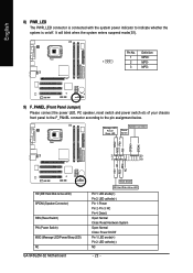
.../off. RESRES+ NC HD (IDE Hard Disk Active LED) SPEAK (Speaker Connector) RES (Reset Switch) PW (Power Switch) MSG (Message LED/Power/Sleep LED) NC GA-945GZM-S2 Motherboard Reset Switch IDE Hard Disk Active LED Pin 1: LED anode(+) Pin 2: LED cathode(-) Pin 1: Power Pin 2- Pin 3: NC Pin 4: Data(-) Open: Normal Close: Reset Hardware...
.../off. RESRES+ NC HD (IDE Hard Disk Active LED) SPEAK (Speaker Connector) RES (Reset Switch) PW (Power Switch) MSG (Message LED/Power/Sleep LED) NC GA-945GZM-S2 Motherboard Reset Switch IDE Hard Disk Active LED Pin 1: LED anode(+) Pin 2: LED cathode(-) Pin 1: Power Pin 2- Pin 3: NC Pin 4: Data(-) Open: Normal Close: Reset Hardware...
Manual
Page 24
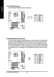
... has digital output function. Use S/PDIF IN feature only when your local dealer. 51 62 Pin No. 1 2 3 4 5 6 Definition Power No Pin SPDIF SPDIFI GND GND GA-945GZM-S2 Motherboard - 24 - Be careful with the polarity of providing digital audio to external speakers or compressed AC3 data to work or even damage it. English 11...
... has digital output function. Use S/PDIF IN feature only when your local dealer. 51 62 Pin No. 1 2 3 4 5 6 Definition Power No Pin SPDIF SPDIFI GND GND GA-945GZM-S2 Motherboard - 24 - Be careful with the polarity of providing digital audio to external speakers or compressed AC3 data to work or even damage it. English 11...
Manual
Page 26
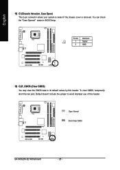
Open: Normal Short: Clear CMOS GA-945GZM-S2 Motherboard - 26 - Pin No. Default doesn't include the jumper to detect if the chassis cover is removed. To clear CMOS, temporarily short the two pins. English 15) CI (Chassis Intrusion, Case Open) This 2-pin connector allows your system to avoid improper use of this header. You can check the "Case Opened" status in BIOS Setup. Definition 1 Signal 1 2 GND 16) CLR_CMOS (Clear CMOS) You may clear the CMOS data to its default values by this header.
Open: Normal Short: Clear CMOS GA-945GZM-S2 Motherboard - 26 - Pin No. Default doesn't include the jumper to detect if the chassis cover is removed. To clear CMOS, temporarily short the two pins. English 15) CI (Chassis Intrusion, Case Open) This 2-pin connector allows your system to avoid improper use of this header. You can check the "Case Opened" status in BIOS Setup. Definition 1 Signal 1 2 GND 16) CLR_CMOS (Clear CMOS) You may clear the CMOS data to its default values by this header.

Manual
Page 28
English GA-945GZM-S2 Motherboard - 28 -
English GA-945GZM-S2 Motherboard - 28 -
Manual
Page 29
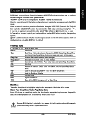
... and the possible selections for Main Menu Main Menu The on-line description of the highlighted setup function is displayed at the bottom of the motherboard. Status Page Setup Menu / Option Page Setup Menu Press to the CMOS SETUP screen. BIOS Setup Quit and not save changes into CMOS ... CMOS, only for Option Page Setup Menu Load the fail-safe default CMOS value from the Internet. CONTROL KEYS Enter> Move to a new BIOS, either GIGABYTE's Q-Flash or @BIOS utility can enter the BIOS setup screen by pressing "Ctrl + F1". When the power is turned off, the battery on , ...
... and the possible selections for Main Menu Main Menu The on-line description of the highlighted setup function is displayed at the bottom of the motherboard. Status Page Setup Menu / Option Page Setup Menu Press to the CMOS SETUP screen. BIOS Setup Quit and not save changes into CMOS ... CMOS, only for Option Page Setup Menu Load the fail-safe default CMOS value from the Internet. CONTROL KEYS Enter> Move to a new BIOS, either GIGABYTE's Q-Flash or @BIOS utility can enter the BIOS setup screen by pressing "Ctrl + F1". When the power is turned off, the battery on , ...


