Manual
Page 5
... CPU 14 1-3-2 Installation of the CPU Cooler 15 1-4 Installation of Memory 16 1-5 Installation of Expansion Cards 18 1-6 I/O Back Panel Introduction 19 1-7 Connectors Introduction 20 Chapter 2 BIOS Setup 31 The Main Menu (For example: GA-945GCMX-S2 BIOS Ver. : F5a 32 2-1 Standard CMOS Features 34 2-2 Advanced BIOS Features 36 2-3 IntegratedPeripherals 38 2-4 Power Management Setup 42...
... CPU 14 1-3-2 Installation of the CPU Cooler 15 1-4 Installation of Memory 16 1-5 Installation of Expansion Cards 18 1-6 I/O Back Panel Introduction 19 1-7 Connectors Introduction 20 Chapter 2 BIOS Setup 31 The Main Menu (For example: GA-945GCMX-S2 BIOS Ver. : F5a 32 2-1 Standard CMOS Features 34 2-2 Advanced BIOS Features 36 2-3 IntegratedPeripherals 38 2-4 Power Management Setup 42...
Manual
Page 12
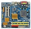
GA-945GCM(X)-S2 Motherboard - 12 - Only for GA-945GCMX-S2. English 1-2 Feature Summary CPU Š LGA775 for Intel® CoreTM 2 Extreme dual-core / CoreTM 2 Duo / Pentium® D / Pentium® 4 / Celeron® D &#...ATX 12V power connector Š 1 floppy connector Š 1 IDE connector Š 4 SATA 3Gb/s connectors Š 1 CPU fan connector Š 1 system fan connector Š 1 front panel connector Š 1 front audio connector Š 1 CD In connector Š 1 S/PDIF In/Out connector Š 2 USB 2.0/1.1 connectors for additional 4 ports by cables Š 1 COMB...
GA-945GCM(X)-S2 Motherboard - 12 - Only for GA-945GCMX-S2. English 1-2 Feature Summary CPU Š LGA775 for Intel® CoreTM 2 Extreme dual-core / CoreTM 2 Duo / Pentium® D / Pentium® 4 / Celeron® D &#...ATX 12V power connector Š 1 floppy connector Š 1 IDE connector Š 4 SATA 3Gb/s connectors Š 1 CPU fan connector Š 1 system fan connector Š 1 front panel connector Š 1 front audio connector Š 1 CD In connector Š 1 S/PDIF In/Out connector Š 2 USB 2.0/1.1 connectors for additional 4 ports by cables Š 1 COMB...
Manual
Page 13
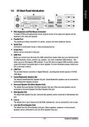
Hardware Installation You must install the FSB 1333 MHz CoreTM 2 CPU with 1333 MHz FSB through overclocking. English Rear Panel I/O Š 1 PS/2 keyboard port Š 1 PS/2 mouse port Š 1 parallel port Š 1 serial port Š 1 D-Sub port Š 4 USB 2.0/1.1 ports Š 1 RJ-45 port Š 6 ...
Hardware Installation You must install the FSB 1333 MHz CoreTM 2 CPU with 1333 MHz FSB through overclocking. English Rear Panel I/O Š 1 PS/2 keyboard port Š 1 PS/2 mouse port Š 1 parallel port Š 1 serial port Š 1 D-Sub port Š 4 USB 2.0/1.1 ports Š 1 RJ-45 port Š 6 ...
Manual
Page 19
... can be connected to Line In jack. Serial Port Connects to the lower port (purple). can be connected to Side Speaker Out jack. English 1-6 I/O Back Panel Introduction PS/2 Keyboard and PS/2 Mouse Connector To install a PS/2 port keyboard and mouse, plug the mouse to the upper port (green) and the keyboard...
... can be connected to Line In jack. Serial Port Connects to the lower port (purple). can be connected to Side Speaker Out jack. English 1-6 I/O Back Panel Introduction PS/2 Keyboard and PS/2 Mouse Connector To install a PS/2 port keyboard and mouse, plug the mouse to the upper port (green) and the keyboard...

Manual
Page 25
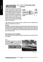
...) RES (Reset Switch) NC Pin 1: LED anode(+) Pin 2: LED cathode(-) Open: Normal Close: Power On/Off Pin 1: Power Pin 2- Hardware Installation English 10) F_PANEL (Front Panel Jumper) Please connect the power LED, PC speaker, reset switch and power switch etc. Message LED/ Power/ Sleep LED Power Switch Speaker Connector MSG+ MSG...(-) Pin 1: LED anode(+) Pin 2: LED cathode(-) Open: Normal Close: Reset Hardware System NC - 25 - PW+ PWSPEAK+ SPEAK- 2 20 1 19 HD+ HD- of your chassis front panel to the F_PANEL connector according to the pin assignment below.
...) RES (Reset Switch) NC Pin 1: LED anode(+) Pin 2: LED cathode(-) Open: Normal Close: Power On/Off Pin 1: Power Pin 2- Hardware Installation English 10) F_PANEL (Front Panel Jumper) Please connect the power LED, PC speaker, reset switch and power switch etc. Message LED/ Power/ Sleep LED Power Switch Speaker Connector MSG+ MSG...(-) Pin 1: LED anode(+) Pin 2: LED cathode(-) Open: Normal Close: Reset Hardware System NC - 25 - PW+ PWSPEAK+ SPEAK- 2 20 1 19 HD+ HD- of your chassis front panel to the F_PANEL connector according to the pin assignment below.
Manual
Page 26
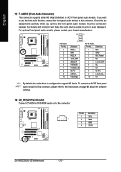
Pin No. Definition 1 CD-L 1 2 GND 3 GND 4 CD-R GA-945GCM(X)-S2 Motherboard - 26 - Check the pin assignments carefully while you wish to use the front audio function, connect the front panel audio module to this connector, please refer to the instructions on page 68 about the software ... audio out to this connector. Incorrect connection between the module and connector will make the audio device unable to support HD Audio. For optional front panel audio module, please contact your chassis manufacturer. 10 9 HD Audio: Pin No. 1 2 3 4 5 6 7 8 9 10 2 Definition MIC2_L ...
Pin No. Definition 1 CD-L 1 2 GND 3 GND 4 CD-R GA-945GCM(X)-S2 Motherboard - 26 - Check the pin assignments carefully while you wish to use the front audio function, connect the front panel audio module to this connector, please refer to the instructions on page 68 about the software ... audio out to this connector. Incorrect connection between the module and connector will make the audio device unable to support HD Audio. For optional front panel audio module, please contact your chassis manufacturer. 10 9 HD Audio: Pin No. 1 2 3 4 5 6 7 8 9 10 2 Definition MIC2_L ...
Manual
Page 57
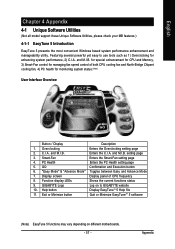
setting page 3. Display screen Display panel of both CPU cooling fan and North-Bridge Chipset cooling fan, 4) PC health for enhancing system performance, 2) C.I .B. Featuring several powerful yet easy to GIGABYTE website 10. for special enhancement for CPU and Memory, 3) ... Function display LEDs Shows the current functions status 9. Overclocking Enters the Overclocking setting page 2. and M.I .B. Appendix and M.I .B. GIGABYTE Logo Log on different motherboards. - 57 - English Chapter 4 Appendix 4-1 Unique Software Utilities (Not all model support these Unique ...
setting page 3. Display screen Display panel of both CPU cooling fan and North-Bridge Chipset cooling fan, 4) PC health for enhancing system performance, 2) C.I .B. Featuring several powerful yet easy to GIGABYTE website 10. for special enhancement for CPU and Memory, 3) ... Function display LEDs Shows the current functions status 9. Overclocking Enters the Overclocking setting page 2. and M.I .B. Appendix and M.I .B. GIGABYTE Logo Log on different motherboards. - 57 - English Chapter 4 Appendix 4-1 Unique Software Utilities (Not all model support these Unique ...
Manual
Page 64
English 4-1-4 2- / 4- / 6- / 8- Multi-channel audio experiences have an Internet chat, make a telephone call over the Internet, and etc. GA-945GCM(X)-S2 Motherboard - 64 - Stereo Speakers Connection and Settings: We recommend that you MUST connect it to the default Mic In jack for instance, listen to...Speaker Out) Mic In Note that support audio output at the same time. For example, if a rear speaker is able to open the Audio Control Panel. STEP 1 : After installation of the audio driver, you should find an Audio Manager icon in your system tray (you can also find the ...
English 4-1-4 2- / 4- / 6- / 8- Multi-channel audio experiences have an Internet chat, make a telephone call over the Internet, and etc. GA-945GCM(X)-S2 Motherboard - 64 - Stereo Speakers Connection and Settings: We recommend that you MUST connect it to the default Mic In jack for instance, listen to...Speaker Out) Mic In Note that support audio output at the same time. For example, if a rear speaker is able to open the Audio Control Panel. STEP 1 : After installation of the audio driver, you should find an Audio Manager icon in your system tray (you can also find the ...
Manual
Page 65
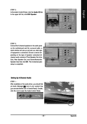
... Line Out jack, a small window will pop up and ask you can also find an Audio Manager icon in Control Panel). Appendix STEP 3: Connect a speaker or headphone to open the Audio Control Panel. - 65 - The 2-channel audio setup is connected. In the upper left list, click 2CH Speaker. Setting Up 4-Channel Audio... the audio driver, you should find the icon in your system tray (you what type of equipment is completed. English STEP 2: In the Audio Control Panel, click the Audio I/O tab.
... Line Out jack, a small window will pop up and ask you can also find an Audio Manager icon in Control Panel). Appendix STEP 3: Connect a speaker or headphone to open the Audio Control Panel. - 65 - The 2-channel audio setup is connected. In the upper left list, click 2CH Speaker. Setting Up 4-Channel Audio... the audio driver, you should find the icon in your system tray (you what type of equipment is completed. English STEP 2: In the Audio Control Panel, click the Audio I/O tab.
Manual
Page 66
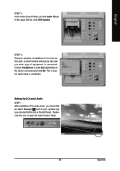
GA-945GCM(X)-S2 Motherboard - 66 - Doubleclick the icon to the audio jacks on the type of speaker connected (4channel audio consists of Front Speaker Out (Line Out) and Rear Speaker Out) and then click OK. STEP 3: Connect the 4-channel speakers to open the Audio Control Panel. In the upper left list,... the audio driver, you should find an Audio Manager icon in your system tray (you can also find the icon in Control Panel). English STEP 2: In the Audio Control Panel, click the Audio I/O tab. Setting Up 6-Channel Audio STEP 1 : After installation of equipment is completed.
GA-945GCM(X)-S2 Motherboard - 66 - Doubleclick the icon to the audio jacks on the type of speaker connected (4channel audio consists of Front Speaker Out (Line Out) and Rear Speaker Out) and then click OK. STEP 3: Connect the 4-channel speakers to open the Audio Control Panel. In the upper left list,... the audio driver, you should find an Audio Manager icon in your system tray (you can also find the icon in Control Panel). English STEP 2: In the Audio Control Panel, click the Audio I/O tab. Setting Up 6-Channel Audio STEP 1 : After installation of equipment is completed.
Manual
Page 67
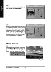
... Choose a device depending on the motherboard and the surround cable, a small window will pop up and ask you can also find the icon in Control Panel). Setting Up 8-Channel Audio STEP 1 : After installation of the audio driver, you should find an Audio Manager icon in your system tray (you what type... audio jacks on the type of speaker connected (6channel audio consists of equipment is completed. STEP 3: Connect the 6-channel speakers to open the Audio Control Panel. - 67 - English STEP 2: In the Audio Control...
... Choose a device depending on the motherboard and the surround cable, a small window will pop up and ask you can also find the icon in Control Panel). Setting Up 8-Channel Audio STEP 1 : After installation of the audio driver, you should find an Audio Manager icon in your system tray (you what type... audio jacks on the type of speaker connected (6channel audio consists of equipment is completed. STEP 3: Connect the 6-channel speakers to open the Audio Control Panel. - 67 - English STEP 2: In the Audio Control...

Manual
Page 68
... of Front Speaker Out (Line Out), Rear Speaker Out, Center/Subwoofer Speaker Out, and Side Speaker Out) then click OK. GA-945GCM(X)-S2 Motherboard - 68 - In the ANALOG area, click the Tool icon and then select the Disable front panel jack detection check box. STEP 3: Connect the 8-channel speakers to the Audio Control...
... of Front Speaker Out (Line Out), Rear Speaker Out, Center/Subwoofer Speaker Out, and Side Speaker Out) then click OK. GA-945GCM(X)-S2 Motherboard - 68 - In the ANALOG area, click the Tool icon and then select the Disable front panel jack detection check box. STEP 3: Connect the 8-channel speakers to the Audio Control...


