Manual
Page 1
GA-945GCM-S2L/ GA-945GCM-S2C LGA775 socket motherboard for Intel® CoreTM processor family/ Intel® Pentium® processor family/Intel® Celeron® processor family User's Manual Rev. 1007 12ME-945GCMS2-1007R
GA-945GCM-S2L/ GA-945GCM-S2C LGA775 socket motherboard for Intel® CoreTM processor family/ Intel® Pentium® processor family/Intel® Celeron® processor family User's Manual Rev. 1007 12ME-945GCMS2-1007R
Manual
Page 2
Motherboard GA-945GCM-S2L/GA-945GCM-S2C Aug. 27, 2007 Motherboard GA-945GCM-S2L/ GA-945GCM-S2C Aug. 27, 2007
Motherboard GA-945GCM-S2L/GA-945GCM-S2C Aug. 27, 2007 Motherboard GA-945GCM-S2L/ GA-945GCM-S2C Aug. 27, 2007
Manual
Page 3
...BYTE TECHNOLOGY CO., LTD as the exclu- For product-related information, check on our website at: http://www.gigabyte.com.tw Identifying Your Motherboard Revision The revision number on our website. No part of documentations: „ For detailed product information, carefully ... by copyright laws and is the property of GIGABYTE. Example: Disclaimer Information in this manual is designated by GIGA-BYTE TECHNOLOGY CO., LTD. For example, "REV: 1.0" means the revision of GIGABYTE branded motherboards. Check your motherboard looks like this: "REV: X.X." Copyright &#...
...BYTE TECHNOLOGY CO., LTD as the exclu- For product-related information, check on our website at: http://www.gigabyte.com.tw Identifying Your Motherboard Revision The revision number on our website. No part of documentations: „ For detailed product information, carefully ... by copyright laws and is the property of GIGABYTE. Example: Disclaimer Information in this manual is designated by GIGA-BYTE TECHNOLOGY CO., LTD. For example, "REV: 1.0" means the revision of GIGABYTE branded motherboards. Check your motherboard looks like this: "REV: X.X." Copyright &#...
Manual
Page 4
Table of Contents Box Contents ...6 OptionalItems...6 GA-945GCM-S2L/GA-945GCM-S2C Motherboard Layout 7 Block Diagram...8 Chapter 1 Hardware Installation 9 1-1 Installation Precautions 9 1-2 Product Specifications 10 1-3 Installing the CPU and CPU Cooler 13 1-3-1 Installing the CPU 13 1-3-2 Installing the CPU ...
Table of Contents Box Contents ...6 OptionalItems...6 GA-945GCM-S2L/GA-945GCM-S2C Motherboard Layout 7 Block Diagram...8 Chapter 1 Hardware Installation 9 1-1 Installation Precautions 9 1-2 Product Specifications 10 1-3 Installing the CPU and CPU Cooler 13 1-3-1 Installing the CPU 13 1-3-2 Installing the CPU ...
Manual
Page 6
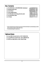
Box Contents GA-945GCM-S2L or GA-945GCM-S2C motherboard Motherboard driver disk User's Manual Quick Installation Guide One IDE cable and one floppy disk drive cable Two SATA 3Gb/s cables I/O Shield • The box contents above are subject to change without notice. • The motherboard image is for reference only and the actual items shall depend on product...
Box Contents GA-945GCM-S2L or GA-945GCM-S2C motherboard Motherboard driver disk User's Manual Quick Installation Guide One IDE cable and one floppy disk drive cable Two SATA 3Gb/s cables I/O Shield • The box contents above are subject to change without notice. • The motherboard image is for reference only and the actual items shall depend on product...
Manual
Page 7
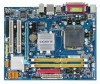
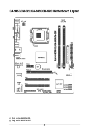
GA-945GCM-S2L/GA-945GCM-S2C Motherboard Layout KB_MS ATX_12V LGA775 CPU_FAN COMA CI GA-945GCM-S2L/GA-945GCM-S2C DDRII1 DDRII2 PWR_LED F_PANEL LPT LAN VGA R_USB ATX IDE USB AUDIO F_AUDIO RTL8111C RTL8101E PCIE_1 PCIE_16 IT8718 PCI1 CODEC PCI2 CD_IN SPDIF_O FDD Intel® 945GC BAT CLR_CMOS MBIOS SYS_FAN F_USB1F_USB2 Intel® ICH7 SATAII3 SATAII2 SATAII1 SATAII0 Only for GA-945GCM-S2C. - 7 - Only for GA-945GCM-S2L.
GA-945GCM-S2L/GA-945GCM-S2C Motherboard Layout KB_MS ATX_12V LGA775 CPU_FAN COMA CI GA-945GCM-S2L/GA-945GCM-S2C DDRII1 DDRII2 PWR_LED F_PANEL LPT LAN VGA R_USB ATX IDE USB AUDIO F_AUDIO RTL8111C RTL8101E PCIE_1 PCIE_16 IT8718 PCI1 CODEC PCI2 CD_IN SPDIF_O FDD Intel® 945GC BAT CLR_CMOS MBIOS SYS_FAN F_USB1F_USB2 Intel® ICH7 SATAII3 SATAII2 SATAII1 SATAII0 Only for GA-945GCM-S2C. - 7 - Only for GA-945GCM-S2L.
Manual
Page 9
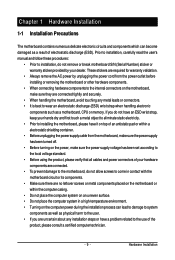
...for warranty validation. • Always remove the AC power by your hardware components are connected. • To prevent damage to the motherboard, do not have an ESD wrist strap, keep your hands dry and first touch a metal object to eliminate static electricity. &#... wrist strap when handling electronic components such as a result of electrostatic discharge (ESD). Chapter 1 Hardware Installation 1-1 Installation Precautions The motherboard contains numerous delicate electronic circuits and components which can lead to damage to system components as well as physical harm to the user. ...
...for warranty validation. • Always remove the AC power by your hardware components are connected. • To prevent damage to the motherboard, do not have an ESD wrist strap, keep your hands dry and first touch a metal object to eliminate static electricity. &#... wrist strap when handling electronic components such as a result of electrostatic discharge (ESD). Chapter 1 Hardware Installation 1-1 Installation Precautions The motherboard contains numerous delicate electronic circuits and components which can lead to damage to system components as well as physical harm to the user. ...
Manual
Page 10
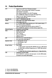
GA-945GCM-S2L/S2C Motherboard - 10 - 1-2 Product Specifications CPU Front Side Bus Chipset Memory Onboard...processor/ Intel® Pentium® 4 processor/ Intel® Celeron® processor in the LGA 775 package (Go to GIGABYTE's website for the latest CPU support list.) Š Support for Intel® Hyper-Threading Technology Š L2 cache varies ... Š Dual channel memory architecture Š Support for DDR2 667/533/400 MHz memory modules (Note 3) (Go to GIGABYTE's website for the latest memory support list.) Š Integrated in the North Bridge Š Realtek ALC662 codec Š ...
GA-945GCM-S2L/S2C Motherboard - 10 - 1-2 Product Specifications CPU Front Side Bus Chipset Memory Onboard...processor/ Intel® Pentium® 4 processor/ Intel® Celeron® processor in the LGA 775 package (Go to GIGABYTE's website for the latest CPU support list.) Š Support for Intel® Hyper-Threading Technology Š L2 cache varies ... Š Dual channel memory architecture Š Support for DDR2 667/533/400 MHz memory modules (Note 3) (Go to GIGABYTE's website for the latest memory support list.) Š Integrated in the North Bridge Š Realtek ALC662 codec Š ...
Manual
Page 12
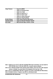
... FSB CPU is installed, the actual memory size displayed will be less than 4 GB. (Note 3) Use of a CoreTM 2 CPU with 1333 MHz FSB through overclocking. GA-945GCM-S2L/S2C Motherboard - 12 - You must install the FSB 1333 MHz CoreTM 2 CPU with DDR2 533 (or above) memory module(s). (Note 2) Due to Windows Vista/XP 32... more than 4 GB of physical memory is required if you wish to install DDR2 667 MHz memory. (Note 4) Available functions in Easytune may differ by motherboard model.
... FSB CPU is installed, the actual memory size displayed will be less than 4 GB. (Note 3) Use of a CoreTM 2 CPU with 1333 MHz FSB through overclocking. GA-945GCM-S2L/S2C Motherboard - 12 - You must install the FSB 1333 MHz CoreTM 2 CPU with DDR2 533 (or above) memory module(s). (Note 2) Due to Windows Vista/XP 32... more than 4 GB of physical memory is required if you wish to install DDR2 667 MHz memory. (Note 4) Available functions in Easytune may differ by motherboard model.
Manual
Page 13
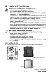
... that supports HT Technology and has it does not meet the standard requirements for instructions on the CPU. Locate the alignment keys on the motherboard CPU socket and the notches on enabling the HT Technology.) 1-3-1 Installing the CPU A. LGA775 CPU Socket Alignment Key LGA 775 CPU Alignment Key... oriented incorrectly. (Or you may occur. • Set the CPU host frequency in accordance with the CPU specifications. mended that the motherboard supports the CPU. (Go to GIGABYTE's website for the latest CPU support list.) • Always turn on the CPU Hardware Installation
... that supports HT Technology and has it does not meet the standard requirements for instructions on the CPU. Locate the alignment keys on the motherboard CPU socket and the notches on enabling the HT Technology.) 1-3-1 Installing the CPU A. LGA775 CPU Socket Alignment Key LGA 775 CPU Alignment Key... oriented incorrectly. (Or you may occur. • Set the CPU host frequency in accordance with the CPU specifications. mended that the motherboard supports the CPU. (Go to GIGABYTE's website for the latest CPU support list.) • Always turn on the CPU Hardware Installation
Manual
Page 14
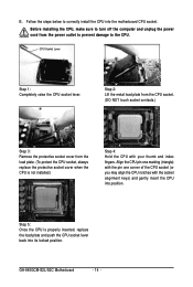
... touch socket contacts.) Step 3: Remove the protective socket cover from the power outlet to prevent damage to correctly install the CPU into its locked position. GA-945GCM-S2L/S2C Motherboard - 14 - Follow the steps below to the CPU. Step 5: Once the CPU is not installed.) Step 4: Hold the CPU with the socket alignment keys...
... touch socket contacts.) Step 3: Remove the protective socket cover from the power outlet to prevent damage to correctly install the CPU into its locked position. GA-945GCM-S2L/S2C Motherboard - 14 - Follow the steps below to the CPU. Step 5: Once the CPU is not installed.) Step 4: Hold the CPU with the socket alignment keys...
Manual
Page 15
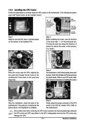
...the CPU. - 15 - Check that the Male and Female push pins are joined closely. (Refer to correctly install the CPU cooler on the motherboard. (The following procedure uses Intel® boxed cooler as the picture above, the installation is to remove the cooler, on the contrary, is ... the steps below to your CPU cooler installation manual for instructions on installing the cooler.) Step 5: After the installation, check the back of the motherboard. Step 4: You should hear a "click" when pushing down on the push pins diagonally. Inadequately removing the CPU cooler may adhere to the...
...the CPU. - 15 - Check that the Male and Female push pins are joined closely. (Refer to correctly install the CPU cooler on the motherboard. (The following procedure uses Intel® boxed cooler as the picture above, the installation is to remove the cooler, on the contrary, is ... the steps below to your CPU cooler installation manual for instructions on installing the cooler.) Step 5: After the installation, check the back of the motherboard. Step 4: You should hear a "click" when pushing down on the push pins diagonally. Inadequately removing the CPU cooler may adhere to the...
Manual
Page 16
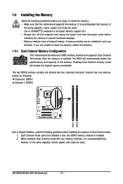
... of the same capacity, brand, speed, and chips be enabled if only one DDR2 memory module is recommended that the motherboard supports the memory. Enabling Dual Channel memory mode will automatically detect the specifications and capacity of the same capacity, brand,...switch the direction. 1-4-1 Dual Channel Memory Configuration This motherboard provides two DDR2 memory sockets and supports Dual Channel Technology. GA-945GCM-S2L/S2C Motherboard - 16 - A memory module can be used . Dual Channel mode cannot be used . (Go to GIGABYTE's website for the latest memory support list.) &#...
... of the same capacity, brand, speed, and chips be enabled if only one DDR2 memory module is recommended that the motherboard supports the memory. Enabling Dual Channel memory mode will automatically detect the specifications and capacity of the same capacity, brand,...switch the direction. 1-4-1 Dual Channel Memory Configuration This motherboard provides two DDR2 memory sockets and supports Dual Channel Technology. GA-945GCM-S2L/S2C Motherboard - 16 - A memory module can be used . Dual Channel mode cannot be used . (Go to GIGABYTE's website for the latest memory support list.) &#...
Manual
Page 17
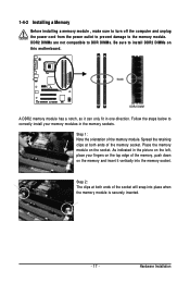
... DIMM A DDR2 memory module has a notch, so it vertically into place when the memory module is securely inserted. - 17 - Place the memory module on this motherboard. Hardware Installation DDR2 DIMMs are not compatible to DDR DIMMs. Be sure to install DDR2 DIMMs on the socket. Spread the retaining clips at both...
... DIMM A DDR2 memory module has a notch, so it vertically into place when the memory module is securely inserted. - 17 - Place the memory module on this motherboard. Hardware Installation DDR2 DIMMs are not compatible to DDR DIMMs. Be sure to install DDR2 DIMMs on the socket. Spread the retaining clips at both...
Manual
Page 18
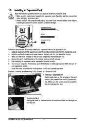
... into the PCI Express x16 slot. If necessary, go to BIOS Setup to correctly install your card. GA-945GCM-S2L/S2C Motherboard - 18 - Secure the card's metal bracket to install an expansion card: • Make sure the motherboard supports the expansion card. Make sure the card is securely seated in your expansion card. • Always...
... into the PCI Express x16 slot. If necessary, go to BIOS Setup to correctly install your card. GA-945GCM-S2L/S2C Motherboard - 18 - Secure the card's metal bracket to install an expansion card: • Make sure the motherboard supports the expansion card. Make sure the card is securely seated in your expansion card. • Always...
Manual
Page 19
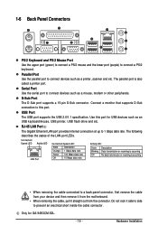
... No data transmission or receiving is also called a printer port. Do not rock it straight out from the motherboard. • When removing the cable, pull it side to side to this port for GA-945GCM-S2L. - 19 - Parallel Port Use the parallel port to connect a PS/2 keyboard. USB Port The USB port supports the...
... No data transmission or receiving is also called a printer port. Do not rock it straight out from the motherboard. • When removing the cable, pull it side to side to this port for GA-945GCM-S2L. - 19 - Parallel Port Use the parallel port to connect a PS/2 keyboard. USB Port The USB port supports the...
Manual
Page 20
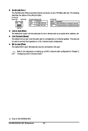
.... Use this jack. RJ-45 LAN Port The Fast Ethernet LAN port provides Internet connection at up a 2/4/5.1-channel audio configuration in jack. GA-945GCM-S2L/S2C Motherboard - 20 - The following describes the states of the LAN port LEDs. Only for a headphone or 2-channel speaker. Mic In Jack (Pink) The default Mic in ...
.... Use this jack. RJ-45 LAN Port The Fast Ethernet LAN port provides Internet connection at up a 2/4/5.1-channel audio configuration in jack. GA-945GCM-S2L/S2C Motherboard - 20 - The following describes the states of the LAN port LEDs. Only for a headphone or 2-channel speaker. Mic In Jack (Pink) The default Mic in ...
Manual
Page 21
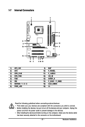
... / 1 / 2 / 3 8) PWR_LED 9) BAT 10) F_PANEL 11) F_AUDIO 12) CD_IN 13) SPDIF_O 14) F_USB1 / F_USB2 15) CLR_CMOS 16) CI Read the following guidelines before turning on the motherboard. - 21 -
... / 1 / 2 / 3 8) PWR_LED 9) BAT 10) F_PANEL 11) F_AUDIO 12) CD_IN 13) SPDIF_O 14) F_USB1 / F_USB2 15) CLR_CMOS 16) CI Read the following guidelines before turning on the motherboard. - 21 -
Manual
Page 22
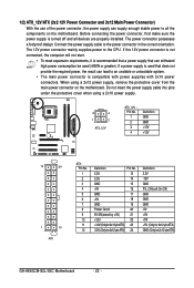
... 3.3V -12V GND PS_ON(soft On/Off) GND GND GND -5V +5V +5V +5V (Only for 2x12-pinATX) GND (Only for 2x12-pin ATX) GA-945GCM-S2L/S2C Motherboard - 22 - The power connector possesses a foolproof design. Connect the power supply cable to the CPU. Do not insert the power supply cable into pins under... the protective cover when using a 2x12 power supply, remove the protective cover from the main power connector on the motherboard. Before connecting the power connector, first make sure the power supply is turned off and all the components on the...
... 3.3V -12V GND PS_ON(soft On/Off) GND GND GND -5V +5V +5V +5V (Only for 2x12-pinATX) GND (Only for 2x12-pin ATX) GA-945GCM-S2L/S2C Motherboard - 22 - The power connector possesses a foolproof design. Connect the power supply cable to the CPU. Do not insert the power supply cable into pins under... the protective cover when using a 2x12 power supply, remove the protective cover from the main power connector on the motherboard. Before connecting the power connector, first make sure the power supply is turned off and all the components on the...
Manual
Page 23
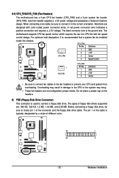
... not place a jumper cap on the headers. 5) FDD (Floppy Disk Drive Connector) This connector is the ground wire. 3/4) CPU_FAN/SYS_FAN (Fan Headers) The motherboard has a 4-pin CPU fan header (CPU_FAN) and a 3-pin system fan header (SYS_FAN). CPU_FAN : Pin No. The types of different color. 33 1 34...wire is used to connect it is typically designated by a stripe of floppy disk drives supported are not configuration jumper blocks. The motherboard supports CPU fan speed control, which requires the use of the connector and the floppy disk drive cable. Before connecting a floppy...
... not place a jumper cap on the headers. 5) FDD (Floppy Disk Drive Connector) This connector is the ground wire. 3/4) CPU_FAN/SYS_FAN (Fan Headers) The motherboard has a 4-pin CPU fan header (CPU_FAN) and a 3-pin system fan header (SYS_FAN). CPU_FAN : Pin No. The types of different color. 33 1 34...wire is used to connect it is typically designated by a stripe of floppy disk drives supported are not configuration jumper blocks. The motherboard supports CPU fan speed control, which requires the use of the connector and the floppy disk drive cable. Before connecting a floppy...


