User Manual
Page 6
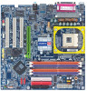
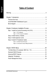
... 5 GA-8TRS350MT Motherboard Layout 7 Block Diagram 8 Chapter 2 Hardware Installation Process 9 Step 1: Install the Central Processing Unit (CPU 10 Step 1-1: CPU Installation 10 Step 1-2 : CPU Cooling Fan Installation 11 Step 2: Install memory modules 12 Step 3: Install expansion cards 15 Step 4: Install I/O Peripherals Cables 16 Step 4-1: I/O Back Panel Introduction 16 Step 4-2: Connectors & Jumper Setting Introduction 18 Chapter 3 BIOS Setup 29 The Main Menu (For example: BIOS Ver. : F2 30 Standard CMOS Features 32 Advanced BIOS Features 35 Integrated Peripherals 36 Power...
... 5 GA-8TRS350MT Motherboard Layout 7 Block Diagram 8 Chapter 2 Hardware Installation Process 9 Step 1: Install the Central Processing Unit (CPU 10 Step 1-1: CPU Installation 10 Step 1-2 : CPU Cooling Fan Installation 11 Step 2: Install memory modules 12 Step 3: Install expansion cards 15 Step 4: Install I/O Peripherals Cables 16 Step 4-1: I/O Back Panel Introduction 16 Step 4-2: Connectors & Jumper Setting Introduction 18 Chapter 3 BIOS Setup 29 The Main Menu (For example: BIOS Ver. : F2 30 Standard CMOS Features 32 Advanced BIOS Features 35 Integrated Peripherals 36 Power...
User Manual
Page 9
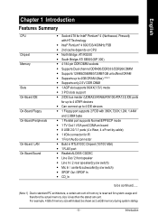
...bytes - 1 Parallel port supports Normal/EPP/ECP mode - 1 TV Out,1 VGA port,COMAon board - 8 USB 2.0/1.1 ports (4 x Rear, 4 x Front by cable) - 1 IrDA connector for up to 4 IDE devices - 1 Floppy port supports 2 FDD with HT Technology - Can connectup to 4GB DRAM (Max) (Note 1) - English Chapter 1 Introduction Features Summary CPU Chip set Memory Slots On-Board IDE On-Board Floppy On-Board Peripherals On-Board LAN On-Board Sound - Supports only 2.5V DDR DIMM - 1 AGP slot supports 8X/4X(1.5V) mode - 3 PCI slots support - 2 IDE bus master (UDMA33/ATA66/ATA100/ATA133) IDE ports for IR...
...bytes - 1 Parallel port supports Normal/EPP/ECP mode - 1 TV Out,1 VGA port,COMAon board - 8 USB 2.0/1.1 ports (4 x Rear, 4 x Front by cable) - 1 IrDA connector for up to 4 IDE devices - 1 Floppy port supports 2 FDD with HT Technology - Can connectup to 4GB DRAM (Max) (Note 1) - English Chapter 1 Introduction Features Summary CPU Chip set Memory Slots On-Board IDE On-Board Floppy On-Board Peripherals On-Board LAN On-Board Sound - Supports only 2.5V DDR DIMM - 1 AGP slot supports 8X/4X(1.5V) mode - 3 PCI slots support - 2 IDE bus master (UDMA33/ATA66/ATA100/ATA133) IDE ports for IR...
User Manual
Page 10
...System Voltage Detect - Supports Q-Flash - GA-8TRS350M T M otherboard - 6 - English Serial ATA On-Board VGA Hardware Monitor I/O Control PS/2 Connector BIOS Additional Features Form Factor - 2 SerialATA connectors (S_ATA1/S_ATA2) - Controlled byATi SB300(IXP 300) - Build in accordance with HT Technology - USB KB/Mouse wake up from S3 - CPU/System Fan Revolution detect - IT8712 - CPU: An Intel® Pentium 4 Processor with your hardware configurations, including CPU, Chipsets, Memory, Cards... .etc. Chipset: An ATi Chipset that supports HT Technology and has it enabled...
...System Voltage Detect - Supports Q-Flash - GA-8TRS350M T M otherboard - 6 - English Serial ATA On-Board VGA Hardware Monitor I/O Control PS/2 Connector BIOS Additional Features Form Factor - 2 SerialATA connectors (S_ATA1/S_ATA2) - Controlled byATi SB300(IXP 300) - Build in accordance with HT Technology - USB KB/Mouse wake up from S3 - CPU/System Fan Revolution detect - IT8712 - CPU: An Intel® Pentium 4 Processor with your hardware configurations, including CPU, Chipsets, Memory, Cards... .etc. Chipset: An ATi Chipset that supports HT Technology and has it enabled...
User Manual
Page 19
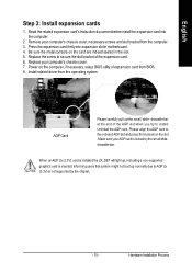
... white- Replace your computer's chassis cover, necessary screws and slot bracket from the computer. 3. Power on the computer, if necessary, setup BIOS utility of the expansion card. 6. Install related driver from BIOS. 8. When an AGP 2x (3.3V) card is installed the 2X_DET will light up normally due to the onboard AGP slot and press firmly down on the card are indeed seated in the slot. 5. Remove your computer's chassis cover...
... white- Replace your computer's chassis cover, necessary screws and slot bracket from the computer. 3. Power on the computer, if necessary, setup BIOS utility of the expansion card. 6. Install related driver from BIOS. 8. When an AGP 2x (3.3V) card is installed the 2X_DET will light up normally due to the onboard AGP slot and press firmly down on the card are indeed seated in the slot. 5. Remove your computer's chassis cover...
User Manual
Page 21
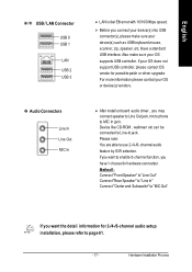
... install onboard audio driver, you may connect speaker to Line Out jack, micro phone to "MIC Out". Please note: You are able to Line-In jack. Device like CD-ROM , walkman etc can be connected to use 2-/4-/6- If yo ur OS does not supp ort USB controller, please contact OS vendor for 2-/4-/6-channel audio setup installation, please refer to enable 6-channel function, you r OS sup ports USB contro ller. English / USB / LAN Connector USB 0 USB 1 LAN USB 2 USB 3 Audio Connectors...
... install onboard audio driver, you may connect speaker to Line Out jack, micro phone to "MIC Out". Please note: You are able to Line-In jack. Device like CD-ROM , walkman etc can be connected to use 2-/4-/6- If yo ur OS does not supp ort USB controller, please contact OS vendor for 2-/4-/6-channel audio setup installation, please refer to enable 6-channel function, you r OS sup ports USB contro ller. English / USB / LAN Connector USB 0 USB 1 LAN USB 2 USB 3 Audio Connectors...
User Manual
Page 25
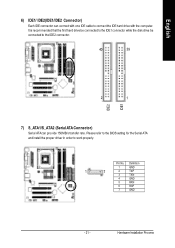
... IDE connector can provide 150MB/s transfer rate. It is recom mended that the first hard drive be connected to the IDE1 connector while the disk drive be connected to the IDE2 connector. 40 39 2 1 IDE2 IDE1 7) S_ATA1/S_ATA2 (Serial ATA Connector) Serial ATA can connect with one IDE cable to work properly. Pin No. Please refer to the BIOS setting for the Serial ATA and install the proper driver in order to connect the IDE hard drive...
... IDE connector can provide 150MB/s transfer rate. It is recom mended that the first hard drive be connected to the IDE1 connector while the disk drive be connected to the IDE2 connector. 40 39 2 1 IDE2 IDE1 7) S_ATA1/S_ATA2 (Serial ATA Connector) Serial ATA can connect with one IDE cable to work properly. Pin No. Please refer to the BIOS setting for the Serial ATA and install the proper driver in order to connect the IDE hard drive...
User Manual
Page 27
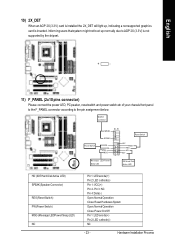
... not boot up , indicating a nonsupported graphics card is not supported by the chipset. + - 11) F_PANEL (2x10 pins connector) Please connect the power LED, PC peaker, resetswitch and power switch etc of your chassis front panel to the F_PANEL connector according to the pin assignment below. Speaker Connector Pow er Swi tch SPEAK- Pin 3: NC Pin 4: Data(-) Open:Normal Operation Close: Reset Hardware System Open:Normal Operation Close:Power On/Off Pin 1: LED anode(+) Pin 2: LED cathode...
... not boot up , indicating a nonsupported graphics card is not supported by the chipset. + - 11) F_PANEL (2x10 pins connector) Please connect the power LED, PC peaker, resetswitch and power switch etc of your chassis front panel to the F_PANEL connector according to the pin assignment below. Speaker Connector Pow er Swi tch SPEAK- Pin 3: NC Pin 4: Data(-) Open:Normal Operation Close: Reset Hardware System Open:Normal Operation Close:Power On/Off Pin 1: LED anode(+) Pin 2: LED cathode...
User Manual
Page 33
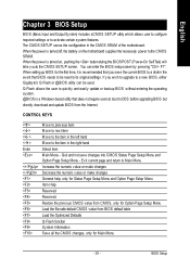
... Main Menu - CONTROL KEYS Enter Move to previous item Move to next item Move to the item in the CMOS SRAM of the motherboard. When the power is turned off, the battery on , pushing the button during the BIOS POST (Power-On Self Test) will take you save changes into CMOS Status Page Setup Menu and Option Page Setup Menu - You can be reset to DOS before upgrading BIOS but directly download and update BIOS from BIOS default table Load...
... Main Menu - CONTROL KEYS Enter Move to previous item Move to next item Move to the item in the CMOS SRAM of the motherboard. When the power is turned off, the battery on , pushing the button during the BIOS POST (Power-On Self Test) will take you save changes into CMOS Status Page Setup Menu and Option Page Setup Menu - You can be reset to DOS before upgrading BIOS but directly download and update BIOS from BIOS default table Load...
User Manual
Page 37
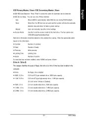
... cy linders Head Number of heads Precomp Write precomp Landing Zone Landing zone Sector Number of floppy disk drive A or drive B that has been installed in . BIOS Setup The four options are used and the sy stem w il skip the automatic detection step and allow for faster sy stem start up. IDE Dev ice Setup. You can manually input the correct settings Access Mode Use this information.
... cy linders Head Number of heads Precomp Write precomp Landing Zone Landing zone Sector Number of floppy disk drive A or drive B that has been installed in . BIOS Setup The four options are used and the sy stem w il skip the automatic detection step and allow for faster sy stem start up. IDE Dev ice Setup. You can manually input the correct settings Access Mode Use this information.
User Manual
Page 41
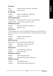
... function. BIOS Setup Disabled Disable USB Key board Support. (Default v alue) USB Mouse Support Enabled Disabled Enable USB Mouse Support. SATA Hotplug Support Enabled Enable SATA hotplug function. (Default v alue) Disabled Disable this function. Surrou ndview This feature enables users to use the internal graphics functionality and an ex ternal VGA card for display at the same time. (note: The ex ternal VGA card y ou install must be built on -chip SATA function. USB Keyboard Support Enabled Enable USB Key board Support. Disable USB Mouse Support. (Default v alue...
... function. BIOS Setup Disabled Disable USB Key board Support. (Default v alue) USB Mouse Support Enabled Disabled Enable USB Mouse Support. SATA Hotplug Support Enabled Enable SATA hotplug function. (Default v alue) Disabled Disable this function. Surrou ndview This feature enables users to use the internal graphics functionality and an ex ternal VGA card for display at the same time. (note: The ex ternal VGA card y ou install must be built on -chip SATA function. USB Keyboard Support Enabled Enable USB Key board Support. Disable USB Mouse Support. (Default v alue...
User Manual
Page 50
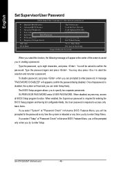
... separate passwords: SUPERVISOR PASSWORD and a USER PASSWORD. When enabled, the Supervisor password is required for entering the BIOS Setup program and having full configuration fields, the User password is required to access only basic items. If y ou select "System" at the center of the screen to assist you select this function, the folowing message will be asked to eight characters, and press . GA-8TRS350MT Motherboard - 46 - A message "PASSWORD DISABLED...
... separate passwords: SUPERVISOR PASSWORD and a USER PASSWORD. When enabled, the Supervisor password is required for entering the BIOS Setup program and having full configuration fields, the User password is required to access only basic items. If y ou select "System" at the center of the screen to assist you select this function, the folowing message will be asked to eight characters, and press . GA-8TRS350MT Motherboard - 46 - A message "PASSWORD DISABLED...
User Manual
Page 56
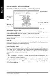
... Q-Flash menu and press Enter button. Later, you will see a box pop up showing the BIOS files you have already put the floppy disk into your keyboard to the floppy disk. Steps: 1. English Exploring the Q-FlashTM / Dual BIOS utility screen The Q-Flash / Dual BIOS utility screen consists of four tasks. GA-8TRS350MT Motherboard - 52 - If you previously downloaded to enable execution of four actions needed to perform these actions. Dual BIOS Utility Boot From Main Bios Main ROM Type/Size SST 49LF004A Backup ROM Type/Size SST 49LF004A Dual BIOS utility...
... Q-Flash menu and press Enter button. Later, you will see a box pop up showing the BIOS files you have already put the floppy disk into your keyboard to the floppy disk. Steps: 1. English Exploring the Q-FlashTM / Dual BIOS utility screen The Q-Flash / Dual BIOS utility screen consists of four tasks. GA-8TRS350MT Motherboard - 52 - If you previously downloaded to enable execution of four actions needed to perform these actions. Dual BIOS Utility Boot From Main Bios Main ROM Type/Size SST 49LF004A Backup ROM Type/Size SST 49LF004A Dual BIOS utility...

User Manual
Page 57
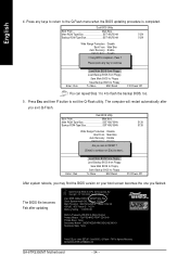
... Backup ROM Type/Size SST 49LF004A 512K 512K Wide Range Protection Disable Bo1ot fFilreo(ms) foMunadin Bios 8KNXPU.Fba Auto Recovery Enable 512K Halt On Error Disable Total size: 1.39MCopy Main ROM Data FtoreBeacskizuep: 911.50K F5 : Refresh Load Default Settings DEL : Delete Save Settings to CMOS Enter : Run Q-Flash Utility Load Main BIOS from Floppy Load Backup BIOS from the floppy disk. The progress of reading the BIOS file from Floppy Save Main BIOS to Floppy Save Backup BIOS to Floppy hi:Move ESC:Reset F10:Power Off BIOS file...
... Backup ROM Type/Size SST 49LF004A 512K 512K Wide Range Protection Disable Bo1ot fFilreo(ms) foMunadin Bios 8KNXPU.Fba Auto Recovery Enable 512K Halt On Error Disable Total size: 1.39MCopy Main ROM Data FtoreBeacskizuep: 911.50K F5 : Refresh Load Default Settings DEL : Delete Save Settings to CMOS Enter : Run Q-Flash Utility Load Main BIOS from Floppy Load Backup BIOS from the floppy disk. The progress of reading the BIOS file from Floppy Save Main BIOS to Floppy Save Backup BIOS to Floppy hi:Move ESC:Reset F10:Power Off BIOS file...
User Manual
Page 58
...512K Enter : Run Wide Range Protection Disable Boot From Main Bios Auto Recovery Enable Halt On Error Disable C!!oCpyopLMyoaaBindIORDSOefMcaoumDltpaSlteaetetttodinB-gasPcaksusp!! Press Esc and then Y button to the Q-Flash menu when the BIOS updating procedure is completed. The computer will restart automatically after updating Award Modular BIOS v6.00PG, An Energy Star Ally Copyright (C) 1984-2003, Award Software, Inc. Press any keys to return to exit the Q-Flash utility. PleaSseavpereSsesttainngyskteoyCtoMOcoSntinue Q-Flash Utility Load Main BIOS from Floppy Load Backup BIOS...
...512K Enter : Run Wide Range Protection Disable Boot From Main Bios Auto Recovery Enable Halt On Error Disable C!!oCpyopLMyoaaBindIORDSOefMcaoumDltpaSlteaetetttodinB-gasPcaksusp!! Press Esc and then Y button to the Q-Flash menu when the BIOS updating procedure is completed. The computer will restart automatically after updating Award Modular BIOS v6.00PG, An Energy Star Ally Copyright (C) 1984-2003, Award Software, Inc. Press any keys to return to exit the Q-Flash utility. PleaSseavpereSsesttainngyskteoyCtoMOcoSntinue Q-Flash Utility Load Main BIOS from Floppy Load Backup BIOS...
User Manual
Page 60
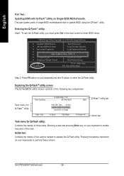
This part guides users of the task. Exploring the Q-FlashTM utility screen The Q-FlashBIOS utility screen consists of three tasks. Entering the Q-FlashTM utility: Step1: To use the Q-Flash utility, you must press Del in the boot screen to update BIOS using the Q-Flash™ utility. CMOS Setup Utility-Copyright (C) 1984-2003 Award Software } Standard CMOS Features Top Performance } Advanced BIOS Features Load Fail-Safe Defaults } Integrated Peripherals Load Optimized Defaults } Power Management Setup Set Supervisor Password } PnP/PCI ConfiguratEionntesr Q-Flash Utility S(...
This part guides users of the task. Exploring the Q-FlashTM utility screen The Q-FlashBIOS utility screen consists of three tasks. Entering the Q-FlashTM utility: Step1: To use the Q-Flash utility, you must press Del in the boot screen to update BIOS using the Q-Flash™ utility. CMOS Setup Utility-Copyright (C) 1984-2003 Award Software } Standard CMOS Features Top Performance } Advanced BIOS Features Load Fail-Safe Defaults } Integrated Peripherals Load Optimized Defaults } Power Management Setup Set Supervisor Password } PnP/PCI ConfiguratEionntesr Q-Flash Utility S(...
User Manual
Page 63
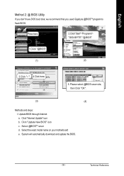
... select @BIOS sever site, then Click "OK". (3) (4) Methods and steps: I. Select the exact model name on your motherboard e. English Method 2: @ BIOS Utility If you don't have DOS boot disk, we recommend that you used Gigabyte @BIOSTM program to flash BIOS. Click "Update New BIOS" icon c. Update BIOS through Internet a. Press here. 2.Click"Start"-"Programs""GIGABYTE"-"@BIOS" 1.Click "@BIOS" (1) (2) 3.Click "P". 4.Click here. 5. Technical Reference System will automatically download and update the BIOS. - 59...
... select @BIOS sever site, then Click "OK". (3) (4) Methods and steps: I. Select the exact model name on your motherboard e. English Method 2: @ BIOS Utility If you don't have DOS boot disk, we recommend that you used Gigabyte @BIOSTM program to flash BIOS. Click "Update New BIOS" icon c. Update BIOS through Internet a. Press here. 2.Click"Start"-"Programs""GIGABYTE"-"@BIOS" 1.Click "@BIOS" (1) (2) 3.Click "P". 4.Click here. 5. Technical Reference System will automatically download and update the BIOS. - 59...
User Manual
Page 78
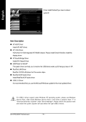
... Driver Install ATi Chipset Driver. n USB Patch for the most updated driver. English Driver install finished!! n USB 2.0 Driver It is recommended that you have to resolve the USB device wake up S3 hang up issue in "Universal Serial Bus controller" under Windows XP operating system, please use the Microsoft Windows update for WinXP This patch driver can help you to reboot system!! n RealTek LAN Driver RealTek 10/100 LAN driver for VGA integrated ATi RS300 chipset. GA-8TRS350MT Motherboard - 74 - Please remove...
... Driver Install ATi Chipset Driver. n USB Patch for the most updated driver. English Driver install finished!! n USB 2.0 Driver It is recommended that you have to resolve the USB device wake up S3 hang up issue in "Universal Serial Bus controller" under Windows XP operating system, please use the Microsoft Windows update for WinXP This patch driver can help you to reboot system!! n RealTek LAN Driver RealTek 10/100 LAN driver for VGA integrated ATi RS300 chipset. GA-8TRS350MT Motherboard - 74 - Please remove...
User Manual
Page 81
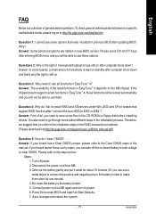
... previous BIOS after I clear CMOS? Question 4: Why do I connect the boot HDD to a floppy disk before installing drivers. Turn off the on-board battery to leak voltage to the steps below: Steps: 1. Answer: The availability of general asked questions based on a specific motherboard model, please log on to make them . Please refer to clear CMOS. If your board has a Clear CMOS jumper, please refer to the installation steps in the RAID manual at our website. (Please download...
... previous BIOS after I clear CMOS? Question 4: Why do I connect the boot HDD to a floppy disk before installing drivers. Turn off the on-board battery to leak voltage to the steps below: Steps: 1. Answer: The availability of general asked questions based on a specific motherboard model, please log on to make them . Please refer to clear CMOS. If your board has a Clear CMOS jumper, please refer to the installation steps in the RAID manual at our website. (Please download...
User Manual
Page 82
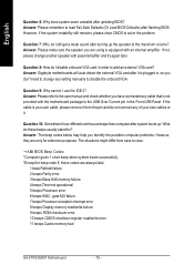
... beep codes below may help you have connected any cable that is your own cables to it from case to the maximum volume? If the cable is not provided with an internal amplifier. Answer: Please make sure the speaker you don't need to disable the onboard VGA. gate A20 failure 7 beeps Processor exception interrupt error 8 beeps Display memory read/write failure 9 beeps ROM checksum error 10 beeps CMOS shutdown register read/write error 11 beeps Cache memory bad GA-8TRS350MT Motherboard...
... beep codes below may help you have connected any cable that is your own cables to it from case to the maximum volume? If the cable is not provided with an internal amplifier. Answer: Please make sure the speaker you don't need to disable the onboard VGA. gate A20 failure 7 beeps Processor exception interrupt error 8 beeps Display memory read/write failure 9 beeps ROM checksum error 10 beeps CMOS shutdown register read/write error 11 beeps Cache memory bad GA-8TRS350MT Motherboard...
User Manual
Page 84
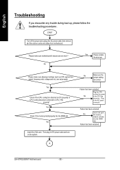
... the memory install properly into the DIMM slot. Failure has been excluded. Yes Check if the CPU cooling fan attached to CPU_FAN properly? English Troubleshooting If you encounter any trouble during boot up, please follow the troubleshooting procedures . No Insert and push the memory module vertically into the DIMM slot. START Turn off the power and unplug the AC power cable, then remove all jumper settings (such as CPU system bus speed, frequency ratio, voltage...
... the memory install properly into the DIMM slot. Failure has been excluded. Yes Check if the CPU cooling fan attached to CPU_FAN properly? English Troubleshooting If you encounter any trouble during boot up, please follow the troubleshooting procedures . No Insert and push the memory module vertically into the DIMM slot. START Turn off the power and unplug the AC power cable, then remove all jumper settings (such as CPU system bus speed, frequency ratio, voltage...


