Manual
Page 13
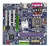
...installation instructions, please refer to the heatsink installation section of the user manual) Fig. 5 Please check the back of motherboard after installing. The heatsink may adhere to the CPU as the picture, the installation is only for Intel boxed fan) Fig. 3 Place the heatsink atop the CPU and make sure the... the Heatsink Male Push Pin The top of Female Push Pin Female Push Pin Fig.1 Please apply an even layer of heatsink paste on the motherboard.Pressing down the push pins diagonally. Fig. 2 (Turning the push pin along the direction of arrow is to remove the heatsink, on the ...
...installation instructions, please refer to the heatsink installation section of the user manual) Fig. 5 Please check the back of motherboard after installing. The heatsink may adhere to the CPU as the picture, the installation is only for Intel boxed fan) Fig. 3 Place the heatsink atop the CPU and make sure the... the Heatsink Male Push Pin The top of Female Push Pin Female Push Pin Fig.1 Please apply an even layer of heatsink paste on the motherboard.Pressing down the push pins diagonally. Fig. 2 (Turning the push pin along the direction of arrow is to remove the heatsink, on the ...

Manual
Page 49
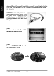
... driver at one time to install it will auto-detect the right USB2.0 driver). - 49 - English Chapter 3 Drivers Installation Pictures below are shown in Windows XP. (1) Please make sure to install the latest service pack for the system. If not, please...mark and restart the system (System will show a question mark "?" Click "GO". System will reboot automatically after OS installation and before installing motherboard drivers. (2) Insert the driver CD that you want then click the "GO" button. Drivers Installation After restarting your system automatically. Just ...
... driver at one time to install it will auto-detect the right USB2.0 driver). - 49 - English Chapter 3 Drivers Installation Pictures below are shown in Windows XP. (1) Please make sure to install the latest service pack for the system. If not, please...mark and restart the system (System will show a question mark "?" Click "GO". System will reboot automatically after OS installation and before installing motherboard drivers. (2) Insert the driver CD that you want then click the "GO" button. Drivers Installation After restarting your system automatically. Just ...
Manual
Page 74
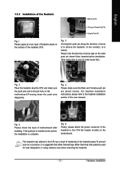
"SURROUND-KIT" is the best solution if you need 6 channel output, Line In and MIC at the same time. GA-8S661FXM-775 Motherboard - 74 - English Advanced 6 Channel Analog Audio Output Mode (using Audio Combo Kit,Optional Device): (Audio Combo Kit provides SPDIF output port : optical & coaxis and...to the SUR_CEN connector on the M/B. STEP 2: Connect the "SURROUND-KIT" cable to rear channels and Center/Subwoofer channels. It is included in the GIGABYTE unique "Audio Combo Kit" as picture. STEP 1: Secure the metal bracket of the "Surround Kit" to the chassis back panel with a screw.
"SURROUND-KIT" is the best solution if you need 6 channel output, Line In and MIC at the same time. GA-8S661FXM-775 Motherboard - 74 - English Advanced 6 Channel Analog Audio Output Mode (using Audio Combo Kit,Optional Device): (Audio Combo Kit provides SPDIF output port : optical & coaxis and...to the SUR_CEN connector on the M/B. STEP 2: Connect the "SURROUND-KIT" cable to rear channels and Center/Subwoofer channels. It is included in the GIGABYTE unique "Audio Combo Kit" as picture. STEP 1: Secure the metal bracket of the "Surround Kit" to the chassis back panel with a screw.

Manual
Page 76
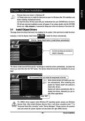
STEP 2: Connect the SPDIF device cable to the SPDIF decoder. The SPDIF_IO cable with a screw. English SPDIF Output Device (Optional Device) A "SPDIF output" device is an optional device. STEP 3: Connect SPDIF to the SPDIF_IO connector on the motherboard. GA-8S661FXM-775 Motherboard - 76 - STEP 1: Secure the metal bracket of the SPDIF Output device to the chassis back panel with rear bracket could link to the "SPDIF_IO" connector (As picture.) For the further linkage to decoder, rear bracket provides coaxial cable and Fiber connecting port.
STEP 2: Connect the SPDIF device cable to the SPDIF decoder. The SPDIF_IO cable with a screw. English SPDIF Output Device (Optional Device) A "SPDIF output" device is an optional device. STEP 3: Connect SPDIF to the SPDIF_IO connector on the motherboard. GA-8S661FXM-775 Motherboard - 76 - STEP 1: Secure the metal bracket of the SPDIF Output device to the chassis back panel with rear bracket could link to the "SPDIF_IO" connector (As picture.) For the further linkage to decoder, rear bracket provides coaxial cable and Fiber connecting port.

Manual
Page 78
English If you set, please press "Manual Selection" to set wrong with the connectors, the warning message will come out as right picture. GA-8S661FXM-775 Motherboard - 78 - Manual setting: If the device picture shows different from what you set .
English If you set, please press "Manual Selection" to set wrong with the connectors, the warning message will come out as right picture. GA-8S661FXM-775 Motherboard - 78 - Manual setting: If the device picture shows different from what you set .

Manual
Page 13
... sink paste be used for detailed installation instructions, please refer to the CPU fan header located on the motherboard. Fig. 4 Please make sure the push pins aim to the CPU as the picture, the installation is only for Intel boxed fan) Fig. 3 Place the heatsink atop the CPU and ...the user manual) Fig. 5 Please check the back of the installed CPU. Hardware Installation The heatsink may adhere to the pin hole on the motherboard.Pressing down the push pins diagonally. English 1-3-2 Installation of the Heatsink Male Push Pin The top of Female Push Pin Female Push Pin Fig.1...
... sink paste be used for detailed installation instructions, please refer to the CPU fan header located on the motherboard. Fig. 4 Please make sure the push pins aim to the CPU as the picture, the installation is only for Intel boxed fan) Fig. 3 Place the heatsink atop the CPU and ...the user manual) Fig. 5 Please check the back of the installed CPU. Hardware Installation The heatsink may adhere to the pin hole on the motherboard.Pressing down the push pins diagonally. English 1-3-2 Installation of the Heatsink Male Push Pin The top of Female Push Pin Female Push Pin Fig.1...
Manual
Page 49
...other drivers. For USB2.0 driver support under "Device Manager". Drivers Installation System will reboot automatically after OS installation and before installing motherboard drivers. (2) Insert the driver CD that you want then click the "GO" button. in the list. After restarting your ...system automatically. English Chapter 3 Drivers Installation Pictures below are shown in Windows XP. (1) Please make sure to install drivers automatically. Please remove the question mark and restart the...
...other drivers. For USB2.0 driver support under "Device Manager". Drivers Installation System will reboot automatically after OS installation and before installing motherboard drivers. (2) Insert the driver CD that you want then click the "GO" button. in the list. After restarting your ...system automatically. English Chapter 3 Drivers Installation Pictures below are shown in Windows XP. (1) Please make sure to install drivers automatically. Please remove the question mark and restart the...

Manual
Page 77
STEP 3: Connect SPDIF to decoder, rear bracket provides coaxial cable and Fiber connecting port. The SPDIF_IO cable with a screw. STEP 2: Connect the SPDIF device cable to the chassis back panel with rear bracket could link to the "SPDIF_IO" connector (As picture.) For the further linkage to the SPDIF decoder. - 77 - Appendix English SPDIF Output Device (Optional Device) A "SPDIF output" device is an optional device. STEP 1: Secure the metal bracket of the SPDIF Output device to the SPDIF_IO connector on the motherboard.
STEP 3: Connect SPDIF to decoder, rear bracket provides coaxial cable and Fiber connecting port. The SPDIF_IO cable with a screw. STEP 2: Connect the SPDIF device cable to the chassis back panel with rear bracket could link to the "SPDIF_IO" connector (As picture.) For the further linkage to the SPDIF decoder. - 77 - Appendix English SPDIF Output Device (Optional Device) A "SPDIF output" device is an optional device. STEP 1: Secure the metal bracket of the SPDIF Output device to the SPDIF_IO connector on the motherboard.
Manual
Page 78
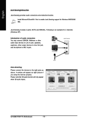
... In jack. A window will only appear when 3D audio inputs. Auto-detecting: Please connect the devices to the right jacks as right picture if you setup the devices properly. GA-8S661FXM-775 Motherboard - 78 - Following is an example for 2 channels (Windows XP): Introduction of audio connectors You may connect CDROM, Walkman or other audio input...
... In jack. A window will only appear when 3D audio inputs. Auto-detecting: Please connect the devices to the right jacks as right picture if you setup the devices properly. GA-8S661FXM-775 Motherboard - 78 - Following is an example for 2 channels (Windows XP): Introduction of audio connectors You may connect CDROM, Walkman or other audio input...


