Manual
Page 4
...GA-8S661FXM-775 Motherboard Layout 6 Block Diagram ...7 Chapter 1 Hardware Installation 9 1-1 Considerations Prior to Installation 9 1-2 Feature Summary 10 1-3 Installation of the CPU and Heatsink 12 1-3-1 Installation of the CPU 12 1-3-2 Installation of the Heatsink 13 1-4 Installation of Memory 14 1-5 Installation of Expansion Cards 15 1-6 I/O Back Panel Introduction 16 1-7 Connectors Introduction 17 Chapter 2 BIOS... Setup 29 The Main Menu (For example: BIOS Ver. : E3 30 2-1 Standard CMOS Features 32 2-2 Advanced BIOS Features 34 2-3 ...
...GA-8S661FXM-775 Motherboard Layout 6 Block Diagram ...7 Chapter 1 Hardware Installation 9 1-1 Considerations Prior to Installation 9 1-2 Feature Summary 10 1-3 Installation of the CPU and Heatsink 12 1-3-1 Installation of the CPU 12 1-3-2 Installation of the Heatsink 13 1-4 Installation of Memory 14 1-5 Installation of Expansion Cards 15 1-6 I/O Back Panel Introduction 16 1-7 Connectors Introduction 17 Chapter 2 BIOS... Setup 29 The Main Menu (For example: BIOS Ver. : E3 30 2-1 Standard CMOS Features 32 2-2 Advanced BIOS Features 34 2-3 ...

Manual
Page 5
Chapter 3 Drivers Installation 49 3-1 Install Chipset Drivers 49 3-2 SoftwareApplications 50 3-3 Driver CD Information 50 3-4 Hardware Information 51 3-5 Contact Us ...51 Chapter 4 Appendix ...53 4-1 Unique Software Utility 53 4-1-1 Xpress Recovery2 Introduction 53 4-1-2 BIOS Flash Method Introduction 55 4-1-3 Serial ATA BIOS Setting Utility Introduction 64 4-1-4 2 / 4 / 6 Channel Audio Function Introduction 71 4-2 Troubleshooting 79 - 5 -
Chapter 3 Drivers Installation 49 3-1 Install Chipset Drivers 49 3-2 SoftwareApplications 50 3-3 Driver CD Information 50 3-4 Hardware Information 51 3-5 Contact Us ...51 Chapter 4 Appendix ...53 4-1 Unique Software Utility 53 4-1-1 Xpress Recovery2 Introduction 53 4-1-2 BIOS Flash Method Introduction 55 4-1-3 Serial ATA BIOS Setting Utility Introduction 64 4-1-4 2 / 4 / 6 Channel Audio Function Introduction 71 4-2 Troubleshooting 79 - 5 -

Manual
Page 7
Block Diagram LGA775 Processor CPUCLK+/- (133/200MHz) AGP 4X/8X AGPCLK (66MHz) VGA Port Host Interface 266/333/400MHz DDR RAM SiS 661FX HCLK+/- (100/133/200MHz) 3 PCI ICS1883 SiS 964 133MHz 33 MHz 14.318 MHz 48 MHz 2 Serial ATA BIOS LPC BUS IT8705AF Floppy LPT Port AC97 Link PCICLK (33MHz) MIC LINE-IN LINE-OUT RJ45 AC97 CODEC 8 USB ATA33/66/100/ Ports 133 IDE Channels 24 MHz 33 MHz PS/2 KB/Mouse COM Ports - 7 -
Block Diagram LGA775 Processor CPUCLK+/- (133/200MHz) AGP 4X/8X AGPCLK (66MHz) VGA Port Host Interface 266/333/400MHz DDR RAM SiS 661FX HCLK+/- (100/133/200MHz) 3 PCI ICS1883 SiS 964 133MHz 33 MHz 14.318 MHz 48 MHz 2 Serial ATA BIOS LPC BUS IT8705AF Floppy LPT Port AC97 Link PCICLK (33MHz) MIC LINE-IN LINE-OUT RJ45 AC97 CODEC 8 USB ATA33/66/100/ Ports 133 IDE Channels 24 MHz 33 MHz PS/2 KB/Mouse COM Ports - 7 -

Manual
Page 11
supports data striping (RAID 0) or mirroring (RAID 1) function - English Onboard SATA RAID Š BIOS Š Š Additional Features Š Š Form Factor Š Onboard SiS964 chipset - supports data transfer rate of licensed AWARD BIOS Supports Q-Flash Supports @BIOS Supports EasyTune Micro-ATX form factor; 24.4cm x 23.0cm - 11 - supports JBOD function - supports a maximum of 2 SATA connections Use of up to 150 MB/s - Hardware Installation supports hot plugging function -
supports data striping (RAID 0) or mirroring (RAID 1) function - English Onboard SATA RAID Š BIOS Š Š Additional Features Š Š Form Factor Š Onboard SiS964 chipset - supports data transfer rate of licensed AWARD BIOS Supports Q-Flash Supports @BIOS Supports EasyTune Micro-ATX form factor; 24.4cm x 23.0cm - 11 - supports JBOD function - supports a maximum of 2 SATA connections Use of up to 150 MB/s - Hardware Installation supports hot plugging function -
Manual
Page 12
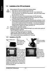
... CPU is installed on the edge of the CPU with the following platform components: - If you wish to the CPU during installation.) GA-8S661FXM-775 Motherboard - 12 - Chipset: An SiS® Chipset that might cause damage to set the frequency beyond hardware specifications since it enabled ... CPU and Heatsink Before installing the CPU, please comply with the triangle and gently insert the CPU into its original position. BIOS: A BIOS that has optimizations for HT Technology 1-3-1 Installation of the following conditions: 1. Fig. 2 Remove the plastic covering on the ...
... CPU is installed on the edge of the CPU with the following platform components: - If you wish to the CPU during installation.) GA-8S661FXM-775 Motherboard - 12 - Chipset: An SiS® Chipset that might cause damage to set the frequency beyond hardware specifications since it enabled ... CPU and Heatsink Before installing the CPU, please comply with the triangle and gently insert the CPU into its original position. BIOS: A BIOS that has optimizations for HT Technology 1-3-1 Installation of the following conditions: 1. Fig. 2 Remove the plastic covering on the ...

Manual
Page 14
... Memory Before installing the memory modules, please comply with the following conditions: 1. The BIOS will automatically detects memory type and size. English 1-4 Installation of the DIMM sockets to lock the DIMM module. Please make sure that the computer power is supported by the motherboard. DDR memory module Fig. 1 Fig. 2 GA-8S661FXM-775 Motherboard - 14 -
... Memory Before installing the memory modules, please comply with the following conditions: 1. The BIOS will automatically detects memory type and size. English 1-4 Installation of the DIMM sockets to lock the DIMM module. Please make sure that the computer power is supported by the motherboard. DDR memory module Fig. 1 Fig. 2 GA-8S661FXM-775 Motherboard - 14 -
Manual
Page 15
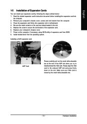
... bracket of the AGP slot when you try to the onboard AGP slot and press firmly down on the computer, if necessary, setup BIOS utility of expansion card from BIOS. 8. Replace your VGA card is locked by following the steps outlined below: 1. Be sure the metal contacts on the card are indeed...
... bracket of the AGP slot when you try to the onboard AGP slot and press firmly down on the computer, if necessary, setup BIOS utility of expansion card from BIOS. 8. Replace your VGA card is locked by following the steps outlined below: 1. Be sure the metal contacts on the card are indeed...
Manual
Page 21
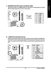
... Connector) Please make sure the pin assigment on the cable is the same as the pin assigment on the MB header. Please refer to the BIOS setting for the Serial ATA and install the proper driver in order to work properly. 1 7 S_ATA (Control by SiS964) Serial ATA can provide up to...
... Connector) Please make sure the pin assigment on the cable is the same as the pin assigment on the MB header. Please refer to the BIOS setting for the Serial ATA and install the proper driver in order to work properly. 1 7 S_ATA (Control by SiS964) Serial ATA can provide up to...
Manual
Page 24
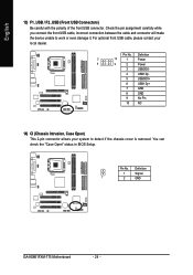
.... Pin No. Pin No. English 13) F1_USB / F2_USB (Front USB Connectors) Be careful with the polarity of the front USB connector. Definition 1 Signal 1 2 GND GA-8S661FXM-775 Motherboard - 24 - You can check the "Case Open" status in BIOS Setup. For optional front USB cable, please contact your system to work or even damage it.
.... Pin No. Pin No. English 13) F1_USB / F2_USB (Front USB Connectors) Be careful with the polarity of the front USB connector. Definition 1 Signal 1 2 GND GA-8S661FXM-775 Motherboard - 24 - You can check the "Case Open" status in BIOS Setup. For optional front USB cable, please contact your system to work or even damage it.
Manual
Page 29
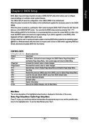
... all the CMOS changes, only for the highlighted item. You can be reset to a new BIOS, either Gigabyte's Q-Flash or @BIOS utility can enter the BIOS setup screen by pressing "Ctrl + F1". Quit and not save the current BIOS to a disk in the CMOS SRAM of the highlighted setup function is turned off, the battery...
... all the CMOS changes, only for the highlighted item. You can be reset to a new BIOS, either Gigabyte's Q-Flash or @BIOS utility can enter the BIOS setup screen by pressing "Ctrl + F1". Quit and not save the current BIOS to a disk in the CMOS SRAM of the highlighted setup function is turned off, the battery...
Manual
Page 30
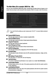
...access hidden advanced options. „ Standard CMOS Features This setup page includes all the items in standard compatible BIOS. „ Advanced BIOS Features This setup page includes all the items of Award special enhanced features. „ Integrated Peripherals This setup...of the system parameters with which the system would be in best performance configuration. GA-8S661FXM-775 Motherboard - 30 - CMOS Setup Utility-Copyright (C) 1984-2004 Award Software ` Standard CMOS Features ` Advanced BIOS Features ` Integrated Peripherals ` Power Management Setup ` PnP/PCI Configurations ` PC ...
...access hidden advanced options. „ Standard CMOS Features This setup page includes all the items in standard compatible BIOS. „ Advanced BIOS Features This setup page includes all the items of Award special enhanced features. „ Integrated Peripherals This setup...of the system parameters with which the system would be in best performance configuration. GA-8S661FXM-775 Motherboard - 30 - CMOS Setup Utility-Copyright (C) 1984-2004 Award Software ` Standard CMOS Features ` Advanced BIOS Features ` Integrated Peripherals ` Power Management Setup ` PnP/PCI Configurations ` PC ...

Manual
Page 31
English „ Set Supervisor Password Change, set , or disable password. BIOS Setup It allows you to limit access to the system and Setup, or just to CMOS and exit setup. „ Exit Without Saving Abandon all CMOS value changes and exit setup. - 31 - It allows you to limit access to the system. „ Save & Exit Setup Save CMOS value settings to Setup. „ Set User Password Change, set , or disable password.
English „ Set Supervisor Password Change, set , or disable password. BIOS Setup It allows you to limit access to the system and Setup, or just to CMOS and exit setup. „ Exit Without Saving Abandon all CMOS value changes and exit setup. - 31 - It allows you to limit access to the system. „ Save & Exit Setup Save CMOS value settings to Setup. „ Set User Password Change, set , or disable password.
Manual
Page 32
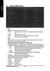
... Number of cylinders Head Number of heads Precomp Write precomp Landing Zone Landing zone Sector Number of the three methods below: Auto Allows BIOS to automatically detect IDE devices during POST. (Default value) None Select this to select this information. to Dec. Jan. The four...system start up. Month The month, from 1999 through 2098. User can use one of sectors GA-8S661FXM-775 Motherboard - 32 - to Sat. Year The year, from Jan. is determined by the BIOS and displayed only. Enter the appropriate option based on this option for the hard drive. to...
... Number of cylinders Head Number of heads Precomp Write precomp Landing Zone Landing zone Sector Number of the three methods below: Auto Allows BIOS to automatically detect IDE devices during POST. (Default value) None Select this to select this information. to Dec. Jan. The four...system start up. Month The month, from 1999 through 2098. User can use one of sectors GA-8S661FXM-775 Motherboard - 32 - to Sat. Year The year, from Jan. is determined by the BIOS and displayed only. Enter the appropriate option based on this option for the hard drive. to...
Manual
Page 33
... memory address map. Floppy 3 Mode Support (for all other errors. Both Drive A & B are 3 mode Floppy Drives. The value of the BIOS. Total Memory This item displays the memory size that used. - 33 - This is detected during the POST. Halt on the motherboard. All, But...3.5 inch double-sided drive; 1.44M byte capacity. (Default value) 3.5 inch double-sided drive; 2.88M byte capacity. Base Memory The POST of the BIOS will determine the amount of memory located above 1 MB in the computer. None No floppy drive installed 360K, 5.25" 5.25 inch PC-type standard ...
... memory address map. Floppy 3 Mode Support (for all other errors. Both Drive A & B are 3 mode Floppy Drives. The value of the BIOS. Total Memory This item displays the memory size that used. - 33 - This is detected during the POST. Halt on the motherboard. All, But...3.5 inch double-sided drive; 1.44M byte capacity. (Default value) 3.5 inch double-sided drive; 2.88M byte capacity. Base Memory The POST of the BIOS will determine the amount of memory located above 1 MB in the computer. None No floppy drive installed 360K, 5.25" 5.25 inch PC-type standard ...
Manual
Page 34
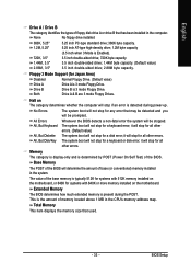
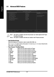
... LAN. USB-CDROM Select your boot device priority by Disabled. Disabled Select your boot device priority by Floppy. GA-8S661FXM-775 Motherboard - 34 - English 2-2 Advanced BIOS Features CMOS Setup Utility-Copyright (C) 1984-2004 Award Software Advanced BIOS Features ` Hard Disk Boot Priority First Boot Device Second Boot Device Third Boot Device Boot Up Floppy Seek...
... LAN. USB-CDROM Select your boot device priority by Disabled. Disabled Select your boot device priority by Floppy. GA-8S661FXM-775 Motherboard - 34 - English 2-2 Advanced BIOS Features CMOS Setup Utility-Copyright (C) 1984-2004 Award Software Advanced BIOS Features ` Hard Disk Boot Priority First Boot Device Second Boot Device Third Boot Device Boot Up Floppy Seek...
Manual
Page 35
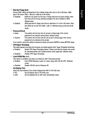
... like NT4. (Defaults value) Disabled Disable CPUID Limit for floppy disk drive to determine if it is 40 or 80 tracks. Note that BIOS can not tell from AGP or PCI VGA card. Init Display First Select the first initiation of the monitor display from 720K, 1.2M or... works for the type of password, please just press ENTER to make [SETUP] empty. Enabled Enable CPU Hyper-Threading feature. BIOS Setup If you install supports Intel® Hyper-Threading Technology. Disabled BIOS will not be any warning message if the drive installed is 360K. (Default value) Enabled...
... like NT4. (Defaults value) Disabled Disable CPUID Limit for floppy disk drive to determine if it is 40 or 80 tracks. Note that BIOS can not tell from AGP or PCI VGA card. Init Display First Select the first initiation of the monitor display from 720K, 1.2M or... works for the type of password, please just press ENTER to make [SETUP] empty. Enabled Enable CPU Hyper-Threading feature. BIOS Setup If you install supports Intel® Hyper-Threading Technology. Disabled BIOS will not be any warning message if the drive installed is 360K. (Default value) Enabled...
Manual
Page 36
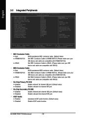
...Values +/-/PU/PD: Value F10: Save F6: Fail-Safe Defaults ESC: Exit F1: General Help F7: Optimized Defaults IDE1 Conductor Cable Auto BIOS autodetects IDE1 conductor cable .(Default Value) ATA66/100/133 Set IDE1 Conductor Cable to ATA33. (Please make sure your IDE device and cable ...) Set IDE2 Conductor Cable to ATA66/100/133 (Please make sure your ATA33 IDE device and cable are compatible with ATA66/100/133). GA-8S661FXM-775 Motherboard - 36 - On-Chip Secondary PCI IDE Enabled Enable onboard 2nd channel IDE port. (Default value) Disabled Disable onboard 2nd channel ...
...Values +/-/PU/PD: Value F10: Save F6: Fail-Safe Defaults ESC: Exit F1: General Help F7: Optimized Defaults IDE1 Conductor Cable Auto BIOS autodetects IDE1 conductor cable .(Default Value) ATA66/100/133 Set IDE1 Conductor Cable to ATA33. (Please make sure your IDE device and cable ...) Set IDE2 Conductor Cable to ATA66/100/133 (Please make sure your ATA33 IDE device and cable are compatible with ATA66/100/133). GA-8S661FXM-775 Motherboard - 36 - On-Chip Secondary PCI IDE Enabled Enable onboard 2nd channel IDE port. (Default value) Disabled Disable onboard 2nd channel ...
Manual
Page 37
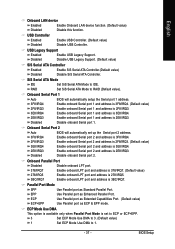
...value) SiS Serial ATA Controller Enabled Disabled Enable SiS Serial ATA Controller.(Default value) Disable SiS Serial ATA Controller. Onboard Serial Port 1 Auto 3F8/IRQ4 BIOS will automatically set to ECP or ECP+EPP. 3 Set ECP Mode Use DMA to 3. (Default value) 1 Set ECP Mode Use DMA to IDE... port 1 and address is 3E8/IRQ4. 2E8/IRQ3 Enable onboard Serial port 1 and address is 3BC/IRQ7. Onboard Serial Port 2 Auto 3F8/IRQ4 BIOS will automatically setup the Serial port 1 address. Enable onboard Serial port 2 and address is 3F8/IRQ4. 2F8/IRQ3 Enable onboard Serial port 2 and ...
...value) SiS Serial ATA Controller Enabled Disabled Enable SiS Serial ATA Controller.(Default value) Disable SiS Serial ATA Controller. Onboard Serial Port 1 Auto 3F8/IRQ4 BIOS will automatically set to ECP or ECP+EPP. 3 Set ECP Mode Use DMA to 3. (Default value) 1 Set ECP Mode Use DMA to IDE... port 1 and address is 3E8/IRQ4. 2E8/IRQ3 Enable onboard Serial port 1 and address is 3BC/IRQ7. Onboard Serial Port 2 Auto 3F8/IRQ4 BIOS will automatically setup the Serial port 1 address. Enable onboard Serial port 2 and address is 3F8/IRQ4. 2F8/IRQ3 Enable onboard Serial port 2 and ...

Manual
Page 39
.... (Default value) Press any key to turn on the computer. Resume by Alarm You can enable Resume by Alarm is Enabled: Month Alarm: Jan.~Dec. BIOS Setup Disabled Enabled Disable this function. (Default value) Enabled Move or click the left button of Month): Everyday, 1~31 Time (hh: mm: ss): (0~23) : (0~59...
.... (Default value) Press any key to turn on the computer. Resume by Alarm You can enable Resume by Alarm is Enabled: Month Alarm: Jan.~Dec. BIOS Setup Disabled Enabled Disable this function. (Default value) Enabled Move or click the left button of Month): Everyday, 1~31 Time (hh: mm: ss): (0~23) : (0~59...
Manual
Page 41
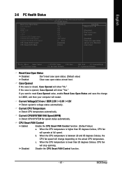
... change depending on the actual CPU temperature. c. When the CPU temperature is opened, Case Opened will show "Yes." Current CPU Temperature Detect CPU temperature automatically. BIOS Setup When the CPU temperature is lower than 65 degrees Celsius, CPU fan will change to be Disabled at next boot KLJI: Move Enter: Select...
... change depending on the actual CPU temperature. c. When the CPU temperature is opened, Case Opened will show "Yes." Current CPU Temperature Detect CPU temperature automatically. BIOS Setup When the CPU temperature is lower than 65 degrees Celsius, CPU fan will change to be Disabled at next boot KLJI: Move Enter: Select...


